


ML7420
Table of contents
 Loading...
PRODUCT DATA
63-2533-03
ML6420, ML7420
Non-Spring Return
Electric Linear Valve Actuators
APPLICATION
The ML6420 Non-Spring Return Electric Linear Valve
Actuators are floating control actuators used with controllers
that provide a switched or floating single-pole double-throw
(spdt) output. These actuators operate standard Honeywell
valves in heating, ventilating, and air conditioning (HVAC)
applications.
The ML7420 Non-Spring Return Electric Linear Valve
Actuators are modulating control actuators used with
controllers that provide an analog output of 0 to 10 Vdc or 2 to
10 Vdc. These actuators operate standard Honeywell valves
in HVAC applications. An internal selector plug can be used to
reverse the direction of action.
FEATURES
• Quick and easy installation.
• No separate linkage required.
• Conduit connector is standard.
• No adjustments required.
• Low power consumption.
• High close-off ratings.
• Force-limiting end switches.
• Manual operator.
• Synchronous motor.
• Corrosion resistant design.
• Maintenance free.
• Direct/reverse acting with ML7420.
• Position feedback signal included with ML7420.
• Selectable 0 to 10 Vdc or 2 to 10 Vdc signal input with
ML7420.
Contents
Application ........................................................................ 1
Installation ........................................................................ 3
Ordering Information ........................................................ 2
Operation .......................................................................... 7
Checkout .......................................................................... 8

ML6420, ML7420 NON-SPRING RETURN ELECTRIC LINEAR VALVE ACTUATORS
63-2533—03 2
ORDERING INFORMATION
When purchasing replacement and modernization products from your TRADELINE® wholesaler or distributor, refer to the
TRADELINE® Catalog or price sheets for complete ordering number.
If you have additional questions, need further information, or would like to comment on our products or services, please write or
phone:
1. Your local Honeywell Automation and Control Products Sales Office (check white pages of your phone directory).
2. Honeywell Customer Care
1885 Douglas Drive North
Minneapolis, Minnesota 55422-4386
3. http://customer.honeywell.com or http://customer.honeywell.ca
In Canada—Honeywell Limited/Honeywell Limitée, 35 Dynamic Drive, Toronto, Ontario M1V 4Z9.
International Sales and Service Offices in all principal cities of the world. Manufacturing in Australia, Canada, Finland, France,
Germany, Japan, Mexico, Netherlands, Spain, Taiwan, United Kingdom, U.S.A.
SPECIFICATIONS
Models:
a
Dependant on actuator model.
Dimensions: See Fig. 1.
Weight: 2.9 lb (1.3 kg).
Electrical Ratings:
Power Input: 24 Vac ±15%, 60 Hz.
Power Consumption:
ML6420: 6 VA maximum at 24 Vac.
ML7420: 7 VA maximum at 24 Vac.
Signal Source Output Resistance: 1K ohm maximum.
Signal Load: 1 mA maximum.
Ambient Ratings:
Temperature:
Ambient: 14°F to 122°F (-10°C to +50°C).
Storage: -40°F to +158°F (-40°C to +70°C).
Maximum Valve Medium: 300°F (150°C).
Humidity: 5 to 95 percent relative humidity, noncondensing.
Stem Force: 135 lbf (600N).
Signal Inputs (Supply Voltage Between Terminals):
ML6420:
B and 24 Vac: Drives valve stem down.
W and 24 Vac: Draws valve stem up.
ML7420: 0 to 10 Vdc or 2 to 10 Vdc.
Actuator Material:
Cover: ABS-FR plastic.
Base: PBTP-FR plastic.
Yoke: Diecast aluminum.
Actuator Stroke: 3/4 in. (20 mm).
Close-off Pressure Ratings: See Table 1.
Protection Standard: IP54.
Approvals:
Canadian Standards Association Listed.
Underwriter’s Laboratories, Inc. UL94-5V Flame Retardant.
Meets CE requirements.
Cable entry: Conduit connector and one knockout on case.
Accessories:
43196000-001 High Temperature Kit (1/2 to 3 in. valves).
Increases temperature range high-end to 428°F
(220°C).
For ML6420/ML6425
43191679-111 Single Auxiliary 10K ohm Potentiometer.
43191679-112 Single Auxiliary 220 ohm Potentiometer.
43191680-105 Dual Auxiliary Switch (for 24 Vac use only).
For ML7420/ML7425
43191680-205 Dual Auxiliary Switch (for 24 Vac use only).
Model
Run Time in
sec at 60 Hz
Stroke in
in. (mm) Description
ML6420A
30 or 60
a
3/4 (20) Electric Linear
Valve Actuator
ML7420A
ML6420, ML7420 NON-SPRING RETURN ELECTRIC LINEAR VALVE ACTUATORS
3 63-2533—03
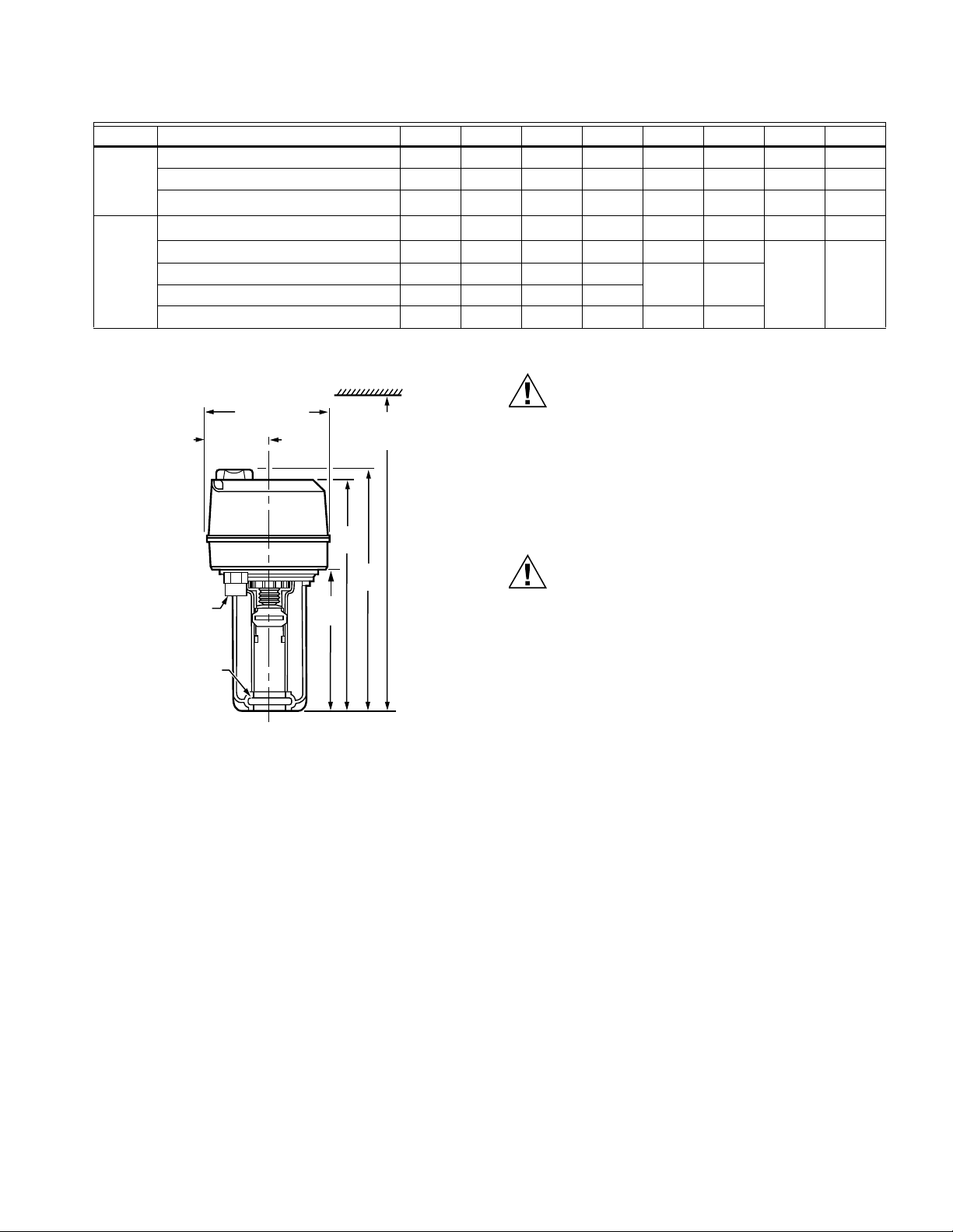
Table 1. Close-off ratings for ML6420, ML7420 Electric Linear Valve Actuators and Honeywell Valves (psi).
a
Represents maximum pressure difference between the outlet and either of the two inlets.
b
Do not exceed 100 psi with V5011G valves used in steam applications.
Fig. 1. Approximate dimensions of ML6420, ML7420
Electric Linear Valve Actuator in in. (mm).
INSTALLATION
When Installing this Product...
1. Read instructions carefully. Failure to follow them could
damage the product or cause a hazardous condition.
2. Check ratings and description given in the specifications
to make sure the product is suitable for your application.
3. Installer must be a trained, experienced service
technician.
4. After installation is complete, check out product
operation as provided in these instructions.
CAUTION
Electrical Shock or Equipment Damage Hazard.
Can shock individuals or short equipment circuitry.
Disconnect power supply before installation.
Location
Install the actuator in a location that allows enough clearance
for mounting accessories and for servicing.
CAUTION
Equipment Damage Hazard.
Can damage actuator due to condensation or a
valve gland leak.
Install the actuator in a position above horizontal.
Mounting
1. Place the actuator on the valve with the U-bolt around
the valve collar. See Fig. 2.
2. Place the U-bolt against the valve collar and secure the
actuator to the valve by turning each U-bolt nut clock-
wise.
NOTE: To assure even pressure on the collar, first
tighten the nuts finger-tight and then alternate
turning each U-bolt nut until both are snug.
3. Push aside the stem button retaining clip and hold. See
Fig. 3.
4. Lift valve stem until the head of the valve stem button is
inside the large slot of the stem button retaining clip on
the actuator.
5. Release the stem button retaining clip to secure the stem
button. Check to make certain the stem button is secured
by the retaining clip.
6. Remove the cover from the actuator using a Phillips or
crosspoint screwdriver. See Fig. 4.
Type Valve 1/2 in. 3/4 in. 1 in. 1-1/4 in. 1-1/2 in. 2 in. 2-1/2 in. 3 in.
FlangeV5011A ——————2816
V3350/3351/3450/3451 — — — — — — 21 14
V5013B,C; V3360/3361/3460/3461 — — — — — —
21
a
14
a
NPT V5011F,G
150
b
150
b
150
b
134
b
77 49 28 16
V5011H,J 150 150 150 145 — — — —
V5011N1xxx, V5011N3xxx, V5013N 230 230 163 104 67 37
V5011N2xxx 100 100 100 100
V5013F 150 150 150 126 77 49
5-5/15
(135)
6-5/16
(161)
x
2-11/16 (67)
12-11/16 (322)
MINIMUM
CLEARANCE
9-3/16
(233)
9-9/16
(242)
5-9/16
(141)
M17419
1/2 (13) FPT
YOKE
DIAMETER
1-3/8 (35)
Loading...