


L6064A
L6064A
Universal Two Speed Fan and Limit Controllers
PRODUCT DATA
APPLICATION
These combination warm air fan and limit controllers
are suitable for all types of forced air heating systems.
The controllers have 2 switches with 3 individually adjustable set points. One switch opens the limit circuit if
the plenum temperature exceeds the preset safety limit;
most models reset automatically. The other switch
changes fan speeds. On all the L6064 the fan speed is
switched from low to high and vice versa according to
the plenum temperature. The fan speed is switched to
low if the plenum temperature falls below the fan off set
point. All the L6064 models are intended for use with
conventional warm air systems.
All models may be used as limit controls by wiring only
the limit side.
Limit controls are suitable for line voltage, low voltage, or millivoltage circuits.
INSTALLATION
When installing this product...
1. Read these instructions carefully. Failure to follow
them could damage the product or cause a hazardous
condition.
2. Check the ratings given in the instructions and on
the product to make sure the product is suitable for your
application.
3. Installer must be a trained, experienced service
technician.
4. After installation is complete, check out product
operation as provided in these instructions.
Follow furnace or burner manufacturer’s instructions, if available. Do not exceed the ratings and limitations given in this section.
ELECTRICAL RATINGS:
NOTE: The electrical rating is at maximum case tem-
perature of 88
O
C (190OF). Use high temperature insulating material, or a mounting bracket when mounting
surface temperature exceeds 88OC (190OF).
CAUTION
!
1. Disconnect power supply before beginning installation to prevent electrical shock or equipment
damage.
2. When connecting cable or conduit to control,
avoid straining the control case.
LOCATION
If this is a replacement installation, locate the
L6064 in the same location as the control being replaced. The L6064 sensing tube length should be
the same as the old control. If this is a new installation, the element should be installed only by a
trained, experienced service technician according
to the furnace manufacturer’s instructions. The element must not touch any internal part of the furnace.
MOUNTING
The device may be mounted as follows:
All models -- Surface or Bracket.
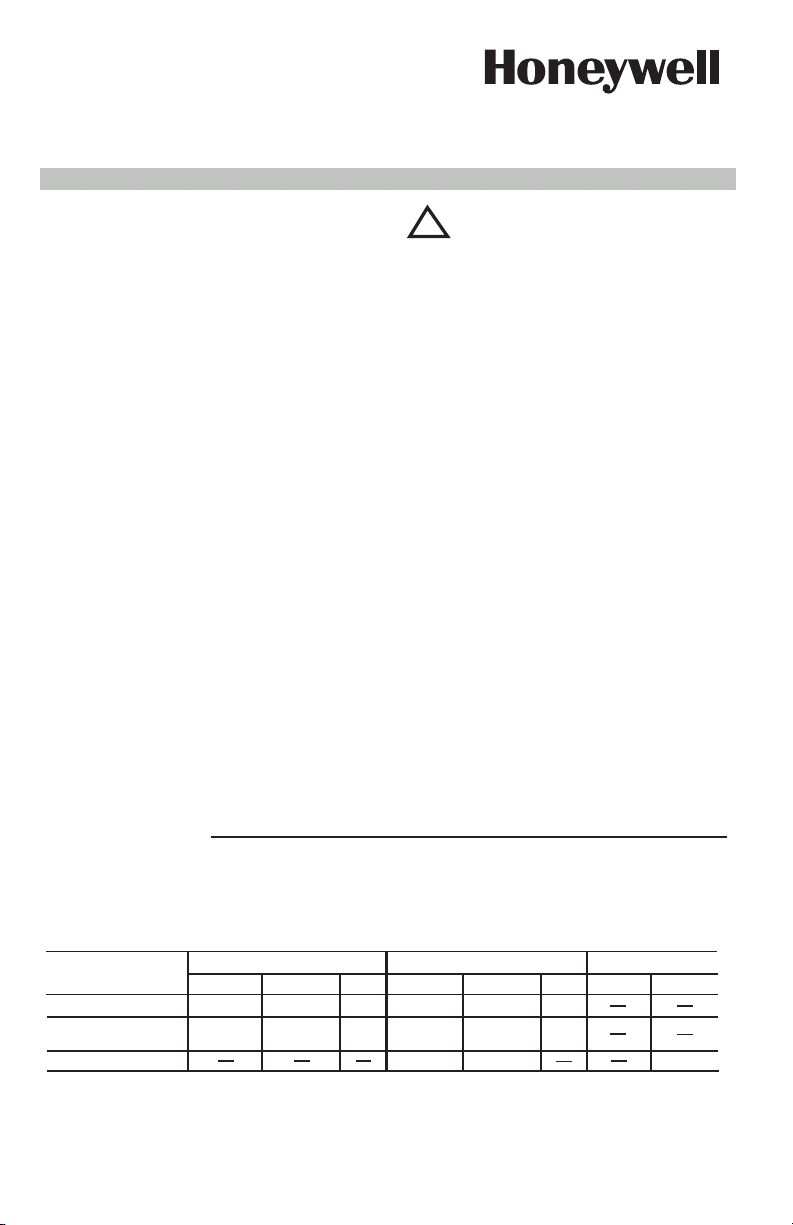
SURFACE MOUNTING
Hole in plenum should be just large enough to
accommodate the 20 mm (3/4 in.) diameter element
tube.
1. Remove cover by squeezing sides and pulling
off. Insert element in plenum and mark location of
mounting holes. Make sure the case is snug against
the plenum before marking the mounting holes.
2. Punch or drill holes for mounting screws.
3. Place insulation between plenum and case if
necessary, or use a mounting bracket.
4. Fasten controller securely with mounting
screws.
90OC field wiring may be required.
NOTE: For applications under DIN or BEAB jurisdiction ambient temperatures must not exceed
O
70
C (158OF).
FAN
24 Vac
LIMIT
2
Full Load (Amps)
Locked Rotor
(Amps)
Max. Amp.
FAN LOW
6 14
120 Vac 240 Vac
FAN HIGH
LIMIT
FAN LOW
8
48
84
FAN HIGH
3
LIMIT
4
7
42
24
Pilot Duty: 2 A at 24 Vac; 0.25 to 12 Vdc. (Limit)
Maximum Combined Connected Load: 2000 VA. ac. Load capacity at terminal points must not exceed the rated
capacity of connected wire at its rated insulation temperature. 75
O
C minimum field wiring is required.
FURNACE
MA
T
RIAU
THERMO-ISOLANT
SI N
CESSAIRE
PL
NUM DE
L’APP
AREIL
DE
CHAUFF
AGE
2697C
!
VIS DE MONT
AGE
APPAREIL
DE
CHAUFF
AGE
PL NUM
SUPPORT RIGIDE
50
100
150
200
250
ON/OFF
FAN LIMIT
FAN
LIMIT
BORNES-
PRESSION POUR
CONDUCTEURS
STANDARDS
(4)
PRISE FEMELLE
POUR LE
RACCORDEMENT
D’UNE BORNE ¸
COSSE M LE DE
6,4 MM (1/4 PO)
(4)
PROTØGE-FILS
POUR RETIRER UN
CONDUCTEUR
STANDARD,
POUSSER AVEC UN
TOURNE-VIS ET
TIRER LE FIL
CONDUCTEUR
STANDARD DE
COMMANDE
D’ QUIPEMENT
CONDUCTEUR AVEC
BORNE ¸ COSSE M LE
DE 6,4 MM (1/4 PO)
(POUSSER LA COSSE AU
FOND DE LA CAVIT .)
Low
CONNECTEUR
M LE RAPIDE
POUR LE
RACCORDEMENT
D’UNE BORNE ¸
COSSE FEMELLE
DE 6,4 MM (1/4 PO)
CONDUCTEUR
AVEC BORNE
EMBROCHABLE
M LE DE 6,4 MM
(1/4 PO) (POUSSER
LA COSSE AU FOND
DE LA CAVIT .)
LOAD
LINE
HIGH LINE
STRIPE GAUGE
ERS
BORNE-PRESSION
VERROUILLABLE
ORIFICE
POUR FIL
PLENUM
HEAT
INSULATING
MATERIAL IF
NEEDED
2697C
Fig. 1 - Surface mounting L6064. Requires hole
20 mm (3/4 in.) diameter in the plenum.
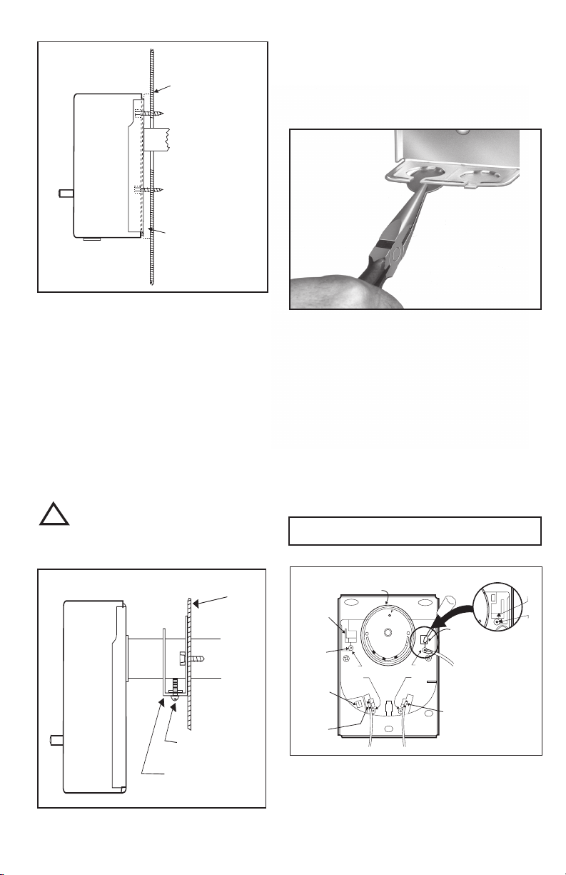
RIGID BRACKET MOUNTING
All models of the L6064 may be mounted using a
rigid bracket. The rigid bracket requires a hole 20
mm (3/4 in.) diameter for mounting.
1. Use bracket as a template to mark the location
of mounting holes in plenum. Drill or punch holes for
mounting screws.
2. Fasten bracket in place with screws furnished.
Tighten the screws securely.
3. Insert element tube through bracket, straighten
controller, and fasten by tightening setscrew.
WARNING
!
Be sure screw strikes tube frame and does not strike
inner sensing element.
WIRING
Disconnect power supply before beginning installation
to prevent electrical shock and equipment damage.
All wiring must comply with local electrical codes and
ordinances. See Fig. 5 for typical hookups.
1. To remove the slotted knockouts, bend down and
break off with a long hose pliers. See Fig. 3.
Fig. 3 - Removing slotted knockouts.
2. Pass wires through bushing before connecting.
3. Connect wire to push-in terminals, and insert the
bushing into knockout slot.
PUSH-IN TERMINALS
1. No. 14, 16, or 18 solid or No. 14 or 16 fused stranded
wire may be connected to the terminals.
2. Strip insulation from wires the distance shown by
the strip guage on the controller.
3. Solid or solder dipped wire may be inserted by pushing into the terminal holes. If stranded wire is used, insert a small screwdriver into the slot next to the terminal. Push in and hold while inserting wire in terminal.
Then remove screwdriver.
All wires must be clear of rotating scaleplate.
IMPORTANT
RIGID BRACKET
SETSCREW
Fig. 2 - Rigid bracket mounting requires a hole 20
mm (3/4 in.) diameter for mounting.
FURNACE
PLENUM
FEMALE
RECEPTACLE FOR
CONNECTION OF
6.4MM (1/4 ") MALE
FLAG TERMINAL
(4)
STANDARD
WIRE PUSH IN
CONNECTORS
(4)
MALE
QUICKCONNECT
FOR CONNECTION
OF 6.4MM (1/4")
FEMALE FLAG
TERMINAL
LEADWIRE WITH
1/4 IN. (6.4MM)
MALE FLAG
TERMINAL (FORCE
FLAG TO BOTTOM
OF CAVITY)
WIRING GUARD
50
FAN LIMIT
ON/OFF
100
200
150
LINE
FAN
HIGH LINE
Low
250
LOAD
LIMIT
STRIPE GAUGE
ERS
TO RELEASE
STANDARD WIRE -
PUSH SCREW
DRIVER IN AND PULL
WIRE OUT
STANDARD
WIRE TO
CONTROLLED
EQUIPMENT
LEADWIRE WITH 1/4 IN.
(6.4 MM) MALE SPADE
TERMINAL (FORCE
FLAG TO BOTTOM OF
CAVITY)
Fig. 4 - Internal view of L6064 showing use of
screwdriver to connect or disconnect
wires at push-in terminals.
NOTE: Because the dial turns when the
element temperature changes, the lettering
on the dial may not be horizontal.
2
PUSH-IN
LOCK
TERMINAL
HOLE
FOR WIRE
A
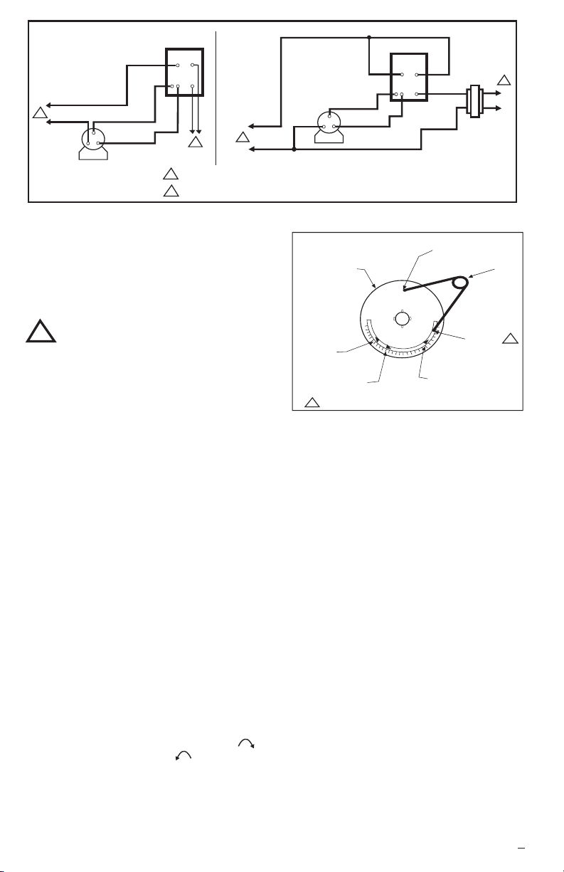
L6064
LIMIT
FAN
SIDE
SIDE
(HOT)
L1
1
L2
LOW SPEED
HIGH SPEED
L1
(HOT)
2
1
ADD DISCONNECT MEANS AND OVERLOAD PROTECTION AS REQUIRED
TO CONTROL LOW VOLTAGE EQUIPMENT
2
1
L2
Fig. 5 - A: Limit in low voltage circuit.
B: Limit in line voltage circuit.
OPERATION
During normal operation, the L6064 sensing element
will rotate and close the fan switch for high speed once
plenum temperature reaches the factory-set fan on set
point.
SETTINGS AND ADJUSTMENTS
CAUTION
!
When adjusting the fan and limit setting levers, hold
the scalepale dial to keep it from turning and straining
the sensing element.
Move the setting levers to the control points recommended by the burner or furnace manufacturer. Use
gentle finger pressure.
1. Move the FAN OFF (continuous low speed) setting
lever to the temperature at which the fan is to run low
speed for continuous air circulation.
All L6064 models - FAN ON (heating fan speed) range
is from 8.3
O
C (15OF) above the FAN OFF (continuous
low speed) setting to 17OC (30OF) below the LIMIT OFF
setting.
2. Move the LIMIT setting lever to the temperature at
which the high limit switch is to break the primary control circuit.
All L6064 models - limit range is 35
O
to 250
F).
O
C to 120OC (95OF
LIMIT SETTING ADJUSTMENT
These controllers have a limit stop which prevents the
limit indicator lever from being adjusted beyond the equipment manufacturer’s specifications.
1. Push the small end of Limit Adjust Tool (196722)
through hole in scaleplate (located at caution marking) to
depress the stop disc not more than 1/16 in. (1.6 mm) to
release stop lock (Fig. 10). Stop disc is on back of
scaleplate.
2. While depressing the stop disc, insert the long end of
Limit Adjust Tool next to limit stop (Fig. 10) and move the
stop to desired setting.
If the L4064 is a replacement control, high limit stop setting should be the same as that of
the control being replaced.
(Move stop clockwise to
lower the setting, counterclockwise to raise it.) Then
remove the limit stop adjust tool.
3. Set the LIMIT OFF lever to the temperature at which
the high limit switch is to open to stop the burner. If the
high limit stop has been properly set, the LIMIT OFF lever
should be as high as the stop permits.
B
L6064
LIMIT
FAN
SIDE
SIDE
LIMIT STOP
ADJUSTABLE
LIMIT STOP
O
C)
TOOL
O
F
2
24V
1
LOW SPEED
HIGH SPEED
SCALEPLATE
CAUTION
DO NOT ROTATE - HOLD DIAL
WHEN SETTING POINTERS
50
FAN
AN
F
OFF
OFF
100
ON
FAN OFF SET
POINT LEVER
FAN ON SET
POINT LEVER
HOMEOWNER: THIS IS A "SAFETY STOP". DO NOT ALTER
1
150
L1
120V
TO RELEASE STOP,
PRESS STIFF WIRE
IN HOLE
250
200
LIMIT SET POINT LEVER
(FACTORY-SET AT 200
L2
(93
Fig. 6 - Changing the high limit stop.
CHECKOUT
Always conduct a thorough checkout immediately following completion of the installation. Operate the system
through at least one complete cycle to ensure that the system operates as intended, especially with respect to the
proper function of the limit control.
The recommended method of checking out the limit control function without disturbing any of the furnace manufacturer’s fan or limit settings is as follows:
1. To stimulate fan motor failure, a broken fan belt, or a
plugged filter, remove the belt driving the fan. On direct
drive fans disconnect the wiring to the fan motor - at the
motor terminal panel - and insulate any live conductors
which might result.
2. Turn the thermostat to the highest setting to ensure
that the burner will run continuously.
3. Watch the operation of the furnace to be sure that
the limit control shuts off the burner when the plenum temperature reaches the limit setting, and that the fan motor
continues to operate. On direct drive fans check to be
sure that voltage is evident on the disconnected leads to
the fan motor when the limit stops the burner.
4. If the installation checks out satisfactorily, replace the
fan belt-or reconnect any direct drive fan wiring-and lower
the thermostat temperature adjustment to the normal setting.
5. If the installation does not check out satisfactorily,
recheck the wiring, correct any wiring discrepancies, and
repeat items 1 through 4. If the installation cannot be made
to function properly DO NOT LEAVE THE FURNACE
OPERATIONAL, PARTICULARLY IF THE LIMIT OR FAN
CONTROLS DO NOT FUNCTION CORRECTLY. REMOVE THE FUSE IN THE CIRCUIT POWERING THE
FURNACE until assistance can be enlisted to correct the
installation.
3
95C-10617B 1
 Loading...