


9-Channel Black&White Multiplexer
HXMT9 / HXMT9X
Installation Manual
WARNING:
TO REDUCE THE RISK OF FIRE OR ELECTRIC SHOCK, DO NOT EXPOSE THIS PRODUCT TO RAIN OR MOISTURE.
DO NOT INSERT ANY METALLIC OBJECT THROUGH VENTILATION GRILLS.
WARNING
RISK OF ELECTRIC SHOCK
DO NOT OPEN
WARNING: TO REDUCE THE RISK OF ELECTRIC SHOCK,
DO NOT REMOVE COVER(OR BACK).
NO USER-SERVICEABLE PARTS INSIDE.
REFER SERVICING TO QUALIFIED SERVICE PERSONNEL.
ENGLISH
Explanation of Graphical Symbols
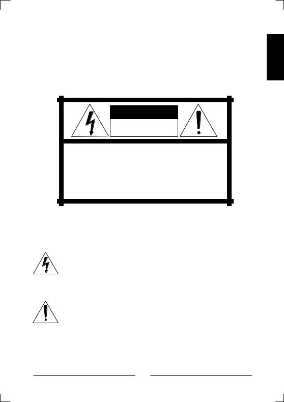
The lightning flash with arrowhead symbol, within an equilateral triangle, is intended to alert the user to the presence of uninsulated "dangerous voltage" within the product's enclosure that may be of sufficient magnitude to constitute a risk of electric shock to persons.
The exclamation point within an equilateral triangle is intended to alert the user to the presence of important operating and maintenance (servicing) instructions in the literature accompanying the product.
iii

Safety Precautions
Should any liquid or solid object fall into the cabinet, unplug the unit and have it checked by qualified personnel before operating it any further.
Unplug the unit from the wall outlet if it is not going to be used for several days or more. To disconnect the cord, pull it out by the plug. Never pull the cord itself.
Allow adequate air circulation to prevent internal heat build-up. Do not place the unit on soft surfaces (rugs, carpets, sofas, etc.) or near materials (curtains, draperies) that may block the ventilation holes.
Height and vertical linearity controls located on the rear panel are for special adjustments by qualified personnel only.
iv

IMPORTANT SAFEGUARDS
1. READ INSTRUCTIONS – Read the safety and operating instructions before operating the unit.
2. RETAIN INSTRUCTIONS – Retain the safety and operating instructions for future reference.
3. CLEANING – Unplug unit from the wall outlet before cleaning. Do not use liquid cleaners or aerosol cleaners. Use a damp cloth for cleaning.
4. ATTACHMENTS – Do not use attachments not approved by the manufacturer as they may result in the risk of fire, electric shock or injury.
5. WATER AND MOISTURE – Do not use unit near water; for example, near a bathtub, washbowl, kitchen sink, laundry tub, in a wet basement, or near a swimming pool.
6. ACCESSORIES – Do not place unit or equipment on an unstable cart, stand or table. The unit or equipment may fall, causing serious injury and serious damage to the equipment. Wall or shelf mounting should follow the manufacturer’s instructions, and should use a mounting kit approved by the manufacturer.
7. CARTS – Video equipment and cart combinations should be moved with care. Quick stops, excessive force and uneven surfaces may cause the equipment and cart combination to overturn.
8. VENTILATION – Slots and openings in the cabinet and the back or bottom are provided for ventilation, to ensure reliable operation of the video equipment and to protect it from overheating. These openings must not be blocked or covered. The openings should never be blocked by placing the unit on a bed, sofa, rug or other similar surface. The unit should never be placed near or over a radiator or heat register. The unit should not be placed in a built-in installation such as a bookcase unless proper ventilation is provided.
9. POWER SOURCES – The unit should be operated only from the type of power source indicated on the marking label. If you are not certain of the type of power supply you have, consult your video equipment dealer or local power company.
10. GROUNDING OR POLARIZATION – This unit may be equipped with a polarized alternating-current line plug (a plug with one blade wider than the other). This plug will fit into the power outlet only one way. This is a safety feature. If you are unable to insert the plug fully into the outlet, try reversing the plug. If the plug still fails to fit, contact your electrician to replace your obsolete outlet. Do not defeat the safety purpose of the polarized plug. If your unit is equipped with a three-wire grounding-type plug (a plug having a third grounding pin), this plug will only fit into a grounding-type power outlet. This is a safety feature. If you are unable to insert the plug into the outlet, contact your electrician to replace your obsolete outlet. Do not defeat the safety purpose of the grounding-type plug.
ENGLISH
v

11.POWER CORDS – Do not allow anything to rest on the power cord. Do not locate unit or equipment where the cord can be damaged by persons walking on it.
12.HEED WARNINGS – Follow all instructions marked on the unit.
13.LIGHTNING – During lightning storms or when the unit will be left unattended and unused for long periods, unplug the unit and associated equipment from the wall outlet. This will prevent damage to the video equipment caused by lightning and power-line surges.
14.OVERLOADING – Do not overload wall outlets and extension cords as this can result in a risk of fire or electric shock.
15.OBJECT AND LIQUID ENTRY – Never push objects of any kind into the unit through openings as they may touch dangerous voltage points or short out parts that could result in a fire or electric shock. Never spill liquid of any kind on the product.
16.SERVICING – Do not attempt to service the unit as opening or removing covers may expose you to dangerous voltage or other hazards. Refer all servicing to qualified service personnel.
17.DAMAGE REQUIRING SERVICE – Unplug the unit and equipment from the wall outlet and refer servicing to qualified service personnel under the following conditions:
A.When the power-supply cord or the plug has been damaged.
B.If liquid has spilled, or objects have fallen into the unit.
C.If the unit has been exposed to rain or water.
D.If the unit does not operate normally when following the operating instructions, adjust only those controls that are covered by the operating instructions as an improper adjustment of other controls may result in damage and will often require extensive work by a qualified technician to restore the unit to its normal operation.
E.If the unit has been dropped or the cabinet damaged.
F.When the unit exhibits a distinct change in performance, this indicates a need for service.
18.REPLACEMENT PARTS – When replacement parts are required, be sure the service technician uses replacement parts specified by the manufacturer or that have the same characteristics as the original part. Unauthorized substitutions may result in fire, electric shock or other hazards.
19.SAFETY CHECK – Upon completion of any service or repairs to the unit, ask the service technician to perform safety checks to determine that the video product is in proper operating condition.
20.FIELD INSTALLATION – Installation should be performed by a qualified service person and should conform to all local codes.
vi

FCC COMPLIANCE STATEMENT
FCC INFORMATION : THIS EQUIPMENT HAS BEEN TESTED AND FOUND TO COMPLY WITH THE LIMITS FOR A CLASS A DIGITAL DEVICE, PURSUANT TO PART 15 OF THE FCC RULES. THESE LIMITS ARE DESIGNED TO PROVIDE REASONABLE PROTECTION AGAINST HARMFUL INTERFERENCE WHEN THE EQUIPMENT IS OPERATED IN A COMMERCIAL ENVIRONMENT. THIS EQUIPMENT GENERATES, USES, AND CAN RADIATE RADIO FREQUENCY ENERGY AND IF NOT INSTALLED AND USED IN ACCORDANCE WITH THE INSTRUCTION MANUAL, MAY CAUSE HARMFUL INTERFERENCE TO RADIO COMMUNICATIONS. OPERATION OF THIS EQUIPMENT IN A RESIDENTIAL AREA IS LIKELY TO CAUSE HARMFUL INTERFERENCE IN WHICH CASE THE USER WILL BE REQUIRED TO CORRECT THE INTERFERENCE AT HIS OWN EXPENSE.
CAUTION : CHANGES OR MODIFICATIONS NOT EXPRESSLY APPROVED BY THE PARTY RESPONSIBLE FOR COMPLIANCE COULD VOID THE USER'S AUTHORITY TO OPERATE THE EQUIPMENT.
THIS CLASS A DIGITAL APPARATUS COMPLIES WITH CANADIAN ICES-003.
CET APPAREIL NUMÉRIQUE DE LA CLASSE A EST CONFORME À LA NORME NMB-003 DU CANADA.
CE COMPLIANCE STATEMENT
WARNING : THIS IS A CLASS A PRODUCT. IN A DOMESTIC ENVIRONMENT THIS PRODUCT MAY CAUSE RADIO INTERFERENCE IN WHICH CASE THE USER MAY BE REQUIRED TO TAKE ADEQUATE MEASURES.
ENGLISH
vii

Table Of Contents Pages
Chapter 1 Introduction |
1 |
Features |
1 |
Technical Overview |
3 |
Chapter 2 Installation |
5 |
Required Tools |
5 |
Connecting Cameras |
5 |
Connecting Monitors |
6 |
Connecting VCRs |
6 |
Connection a Mouse |
7 |
Daisy-Chaining and Remote Control Connections |
7 |
Alarms and Other Connections |
8 |
Initial Setup |
8 |
Accessing the Main Menu |
8 |
Main Menu Settings |
10 |
Time, Date Setup |
11 |
Camera Access Setup |
13 |
Camera Title Setup |
14 |
Camera Sequence Setup |
15 |
Alarm Setup |
16 |
Alarm I/O Setup |
18 |
Alarm Action Setup (1) |
19 |
Alarm Action Setup (2) |
20 |
Associated Camera Setup |
22 |
Motion Action Setup (1) |
23 |
Motion Action Setup (2) |
24 |
Video Loss Action Setup |
25 |
Manual Alarm Action Setup (1) |
27 |
Manual Alarm Action Setup (2) |
29 |
Macro Link Setup |
30 |
Alarm History |
31 |
Motion Detection Setup |
32 |
viii

Motion Detection Index Setup
Motion Detection Index List
Motion Detection Schedule Setup
Motion Detection Sensor Setup
Motion Detection Sensor Setup (Normal)
Testing Motion Detection Sensor Setup
Motion Detection Sensor Setup (Vector)
Playback & Recording Setup
VCR System Setup
Recording Index Setup
Camera Picture Adjustment
Macro Setup
Macro Record Setup
Macro Schedule Setup
Unit Setup
Password Setup
Assigning Passwords
Chapter 3 Operation
Buttons and Their Functions
Menu Operation
Top Menu
Bottom Menu
Live Screen
Pop Up Menu
Live Camera Change
VCR Camera Change
Zoom
Full
Priority On
Histogram Equalizer
Panic Record On
Freeze On
Sequence
Utilities
ix
33
34
35
36
38
39
40
40
41
42
43
45
46
47
48
50
51
53
53
56
56
56
57
58
59
60
61
62
62
62
63
63
63
64
ENGLISH

User Scrn Chg… |
64 |
OSD Change… |
66 |
Screen Protect… |
67 |
Manual Alarm… |
67 |
Alarm Reset |
67 |
Spot Output… |
68 |
Macro |
68 |
User Change… |
68 |
Alarm List… |
69 |
Playback Format… |
70 |
PB Picture Adjust… |
70 |
Appendix A Troubleshooting |
71 |
Appendix B Connector Pin Outs |
72 |
Appendix C Remote Control |
74 |
Remote Control for Daisychained Multiplexers |
74 |
Remote Command Set |
75 |
Functional remote commands |
76 |
Appendix D Specifications |
77 |
Operating Defaults |
77 |
Factory Defaults |
77 |
Video Format |
80 |
Video Level |
80 |
Main Output Display Formats (live and playback) |
80 |
Resolution (pixels x lines) |
80 |
Sampling Standard |
81 |
Video Memory |
81 |
Refresh Rate (fields/sec.) |
81 |
Display Options |
81 |
Motion Detection |
82 |
VCR Playback |
82 |
Alarm Operation |
82 |
x
On-Screen Display (Main)
On-Screen Display (Spot)
Other Features (Internal)
Other Features (External Interface)
Remote Control
Rear Panel Connectors
Front Panel Controls
Power Requirements
Power Adapter
Dimensions
Weight
Operating Environment
83
83
83
84
84
84
85
85
85
86
86
86
ENGLISH
xi

List of Illustraions
Figure 1 — Typical multiplexer system configuration |
1 |
Figure 2 — multiplexer connections |
5 |
Figure 3 — Connecting one VCR to the multiplexer |
6 |
Figure 4 — Connecting two VCRs to the multiplexer |
7 |
Figure 5 — Top menu bar |
8 |
Figure 6 — Supervisor Password screen |
9 |
Figure 7 — Main Menu screen |
10 |
Figure 8 — Time, Date Setup, first screen |
10 |
Figure 9 — Time, Date Setup, second screen |
12 |
Figure 10 — Camera Access Setup screen |
13 |
Figure 11 — Camera Title Setup screen |
14 |
Figure 12 — Camera Sequence Setup screen |
15 |
Figure 13 — Alarm Setup screen |
16 |
Figure 14 — Alarm I/O Setup screen |
18 |
Figure 15 — Alarm Action Setup (1) screen |
19 |
Figure 16 — Alarm Action Setup (2) screen |
20 |
Figure 17 — Associated Camera Setup submenu |
22 |
Figure 18 — Motion Action Setup (1) screen |
23 |
Figure 19 — Motion Action Setup (2) screen |
24 |
Figure 20 — Video Loss Action Setup screen |
25 |
Figure 21 — Manual Alarm Action Setup (1) screen |
27 |
Figure 22 — Manual Alarm Action Setup (2) screen |
29 |
Figure 23 — Macro Link Setup screen |
30 |
Figure 24 — Alarm History List screen |
31 |
Figure 25 — Motion Detection Setup screen |
32 |
Figure 26 — Motion Detection Index Setup screen |
33 |
Figure 27 — Motion Detection Index List screen |
34 |
Figure 28 — Motion Detection Schedule Setup schedule |
35 |
Figure 29 — Motion Detection Sensor Setup screen |
36 |
Figure 30 — Motion Detection Sensor Setup (Normal) screen |
38 |
Figure 31 — Motion Detection Sensor Setup test screen |
39 |
Figure 32 — Playback & Recording Setup screen |
40 |
xii

Figure 33 — VCR System Setup screen |
41 |
Figure 34 — Recording Index Setup screen |
42 |
Figure 35 — Camera Picture Adjustment screen |
43 |
Figure 36 — Macro Setup screen |
45 |
Figure 37 — Macro Recor Setup screen |
46 |
Figure 38 — Live screen with M01 REC on the screen |
47 |
Figure 39 — Macro Schedule Setup screen |
47 |
Figure 40 — Unit Setup screen |
48 |
Figure 41 — Passwords Setup screen |
50 |
Figure 42 — Password entry screen |
51 |
Figure 43 — Front Panel |
53 |
Figure 44 — Top Menu |
56 |
Figure 45 — Bottom Menu |
56 |
Figure 46 — 3x3 Live Screen |
57 |
Figure 47 — Pop Up menu |
58 |
Figure 48 — Live Cam Change menu |
59 |
Figure 49 — VCR Cam Change menu |
60 |
Figure 50 — Zoom Screen |
61 |
Figure 51 — Histogram Equalizer menu bar |
62 |
Figure 52 — Sequence menu |
63 |
Figure 53 — Utilities Pop Up menu |
64 |
Figure 54 — User Screen Change menu bar |
64 |
Figure 55 — Select a Screen menu |
65 |
Figure 56 — OSD Setup screen |
66 |
Figure 57 — Spot output change screen |
68 |
Figure 58 — User Change menu |
68 |
Figure 59 — Alarm History List |
69 |
Figure 60 — Select Format menu |
70 |
Figure 61 — Connetor Sub-Board |
72 |
Figure 62 — RS-485 Connector |
73 |
Table 1 — Re-Address Commands |
74 |
Table 2 — Front key emulation commands |
75 |
Table 3 — Remote commands |
76 |
ENGLISH
xiii

xiv
Chapter 1
Introduction
ENGLISH
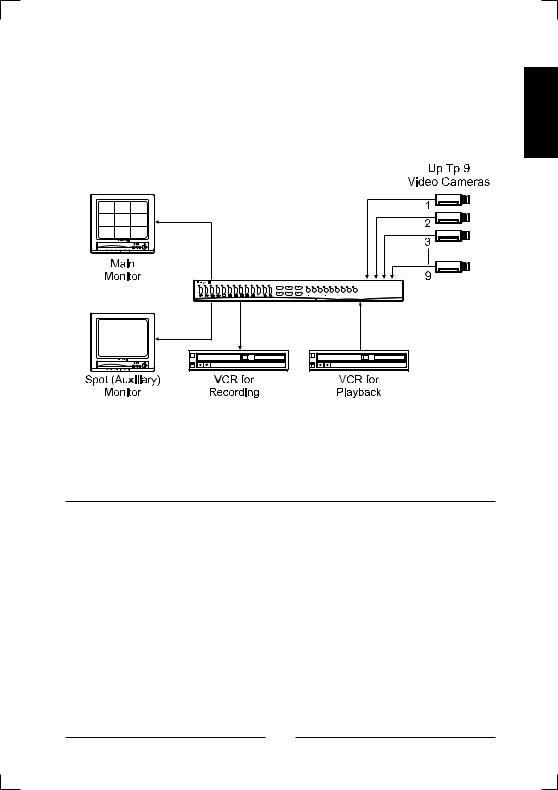
< Figure 1 > Typical multiplexer system configuration.
Features
•Compatible with standard Black&White cameras and other standard Video sources
•Switchable between EIA and CCIR
•Able to decode tapes from many other brands of multiplexers
•Many user-selectable display formats, Cameras can be assigned to any display format
•Multiple monitor outputs (1 Main, 4 Auxiliary) allow simultaneous multi-camera and full-screen viewing
•Multilingual setup menus include English, French, Italian, German, Polish and Spanish
•On-screen display includes date, time, alarm status, video loss, camera number and 24-character camera titles
•Programmable day and night motion-detection schedules
1

•Each camera has a programmable 256-target (16 x 16) motiondetection grid
•Programmable vector-based motion detection in any direction
•Nonvolatile program memory saves all user settings and protects them against power outages
•One TTL/CMOS contact closure alarm for each camera
•Up to 4 cameras can be associated with a single contact closure alarm
•Alarm input polarity is user selectable
•VCR switch pulse input for synchronization with VCRs having switch pulse feature
•Full triplex operation allows simultaneous recording, playback and live viewing
•256-event alarm history log
•Linear Zoom in and out up to 32 times
2

Technical Overview
9 Camera Multiplexing with Motion Detection, Alarm Association and Multilingual Setup Menus
The multiplexer has revolutionary features not available in most multiplexers. The multiplexer has a sophisticated motion detection system that can sense motion vectors in any direction. Motion detection sensitivity can be adjusted and the user can set day and night motion detection schedules. A motion tracking box gives visual indications for easy setup.
The multiplexer has composite BNC input and output for VCR. The main monitor can be connected to either a composite BNC. There are four BNC auxiliary outputs that can be used for “spot” monitors or as sources of video for other devices.
The multiplexer has a large selection of user selectable display formats. It also has digital zooming from 1 to 32 times.
The multiplexer multilingual menu options allow for easy setup. The user’s configuration is stored in nonvolatile memory so that it will not be lost during power outages.
The multiplexer can play back videotapes recorded with many other multiplexers. These include, but are not limited to; Dedicated Micros, ULTRAK Legacy Color, ULTRAK Legacy B/W, Robot, Kalatel and Pelco. Up to 9 multiplexers can be “daisy chained” and addressed and controlled by a single control panel. The multiplexer can also be addressed by a computer using either an RS-232 or RS-485 connection.
ENGLISH
3

4
Chapter 2
Installation
Required Tools
Although no special tools are required to install the multiplexer, it is only one part of a complex system. Refer to the Installation manuals for the other components in your particular installation for special tool requirements.
Up to 9
Cameras
Up to 9 Sensors or Contacts
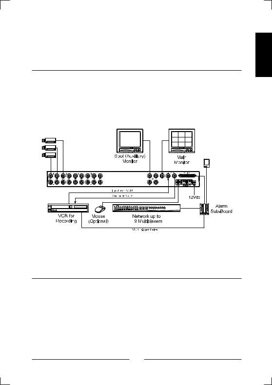
< Figure 2 > multiplexer connections.
Connecting Cameras
You can connect up to 9 cameras to the multiplexer. Connect the camera BNCs to the IN BNC connectors (top row). The loop-through connectors (OUT) are auto-terminated, so terminating resisters are not needed if you do not loop video out to another device.
NOTE : Connecting a cable to the loop-through connector switches off the termination. Do NOT connect a cable to the loop-through BNC connectors unless it is connected to the input of another video device.
ENGLISH
5
Connecting Monitors
Your main monitor should be connected to the MAIN output.
Up to four auxiliary monitors can be connected to the multiplexer. You can use these as spot monitors or to view live video while playing tapes back through the main monitor. The auxiliary monitors should be connected to the AUX BNC connectors.
Connecting VCRs
There are BNC connectors for the VCRs.
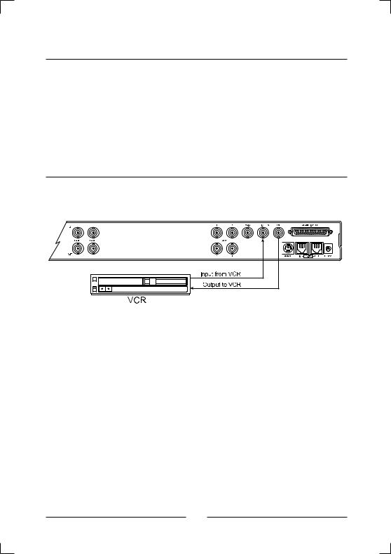
< Figure 3 > Connecting one VCR to the multiplexer.
6
ENGLISH
< Figure 4 > Connecting two VCRs to the multiplexer.
You can connect one VCR to the multiplexer and use it for both recording and playback. However, the multiplexer can handle recording and playback at the same time, so it is possible to connect two VCRs. One VCR is used to record while the other is used to play back. (See the illustrations.)
Connecting a Mouse
The multiplexer menus can be controlled by either buttons on the front panel or by a mouse. If you plan to use a mouse, connect it to the miniDIN connector labeled MOUSE.
The multiplexer is not compatible with all mouse available in the market. Please note that users are recommended to use "Recommended mouse" only described in the manual.
Logitech mouse (Ball mouse only)
NOTE : Compatible mouse can be added without prior notice for better performance.
DaisyChaining and Remote Control Connections
The multiplexer can be daisy-chained to other multiplexers or controlled by a remote keyboard. To add another multiplexer to your system, connect the RS-485 OUT connector of the additional unit to the IN RS485 connector. (See Setup Menu section to set multiplexer address.)
The remote keyboard should be connected to the OUT connector on the multiplexer.
7
Alarms and Other Connections
The 50-pin ALARM IN/OUT connector has 9 alarm inputs, 9 alarm outputs, RS-232 connectors, VCR trigger pulse and various alarm settings. See Appendix B — Connector Pin Outs for further details on how to make these connections.
Initial Setup
Setting up for EIA or CCIR Operation
NOTE : When changing the multiplexer to EIA or CCIR all other settings |
||||
are returned to the factory defaults. |
|
|
||
The multiplexer can be used with either EIA or CCIR systems. |
||||
To set it up for EIA operation: |
|
|
|
|
1) |
Turn off the power |
|
|
|
2) |
Press and hold the |
and {M} buttons. |
||
3) |
Turn on the power |
|
|
|
To set up the multiplexer for CCIR operation: |
||||
1) |
Turn off the power |
|
|
|
2) |
Press and hold the |
and |
|
buttons. |
|
||||
3) |
Turn on the power |
|
|
|
Accessing the Main Menu
NOTE : To access the Main Menu you must have a Supervisor Password. The last item of the Main Menu is the Password Setup. Keep the passwords you create in a safe place. The new passwords will be the only way to access certain features of the multiplexer once you have changed from the factory default passwords.
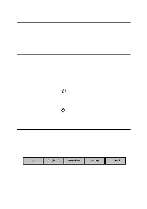
< Figure 5 > Top menu bar.
8

To access the Main Menu of the setup screens, move the cursor to the top of the screen. The top menu bar appears. Select Setup.
ENGLISH
< Figure 6 > Supervisor Password screen.
Enter the password by moving the cursor over the desired number and clicking on it. As you enter each digit, the circles beside “Supervisor Password” fill in and move to the right. Once you have entered all four digits, click on OK. If you have entered the correct four-digit number, the Main Menu will appear. If you have entered an incorrect number, Incorrect Password displays for ten seconds and then the unit returns to a live display.
The factory default passwords are listed in the Technical Specifications.
Click on Cancel to exit the Supervisor Password screen and return to live display.
9

Main Menu Settings
< Figure 7 > Main Menu screen.
< Figure 8 > Time, Date Setup, first screen.
10

Time, Date Setup
In addition to setting the multiplexer’s time and date, these screens can be used to set the format and select daylight saving time. You can use the arrow buttons on the multiplexer or mouse to select the menu item.
Press SET or the left mouse button to decrease the number. Press ESC or the right mouse button to increase the number.
•Date format : There are three date formats to choose from. The month and days are each two-digit numbers represented by MM and DD. Years are four-digit numbers represented by YYYY. The U.S. format is: MM-DD-YYYY. Europe’s format is: DD-MM-YYYY. Asia’s format is: YYYY-MM-DD.
•Hour format : There are two hour formats to choose from. One is 24hour (military) time. The second is AM/PM.
•Clock Source : There are two choices for the clock source. If your multiplexer is connected to a network, set the option to Network Clock and the unit will receive the clock information from the master multiplexer. If your multiplexer is not connected to a network, set the option to Internal Clock.
•Year : Use the arrow or mouse buttons to change the year.
•Month : Use the arrow or mouse buttons to change the month.
•Date : Use the arrow or mouse buttons to change the date.
•Hour : Use the arrow or mouse buttons to change the hour.
•Minute : Use the arrow or mouse buttons to change the minute.
•Second : Use the arrow or mouse buttons to change the second.
•Next > : Selecting this takes you to the second Daylight Saving setup Screen.
ENGLISH
11
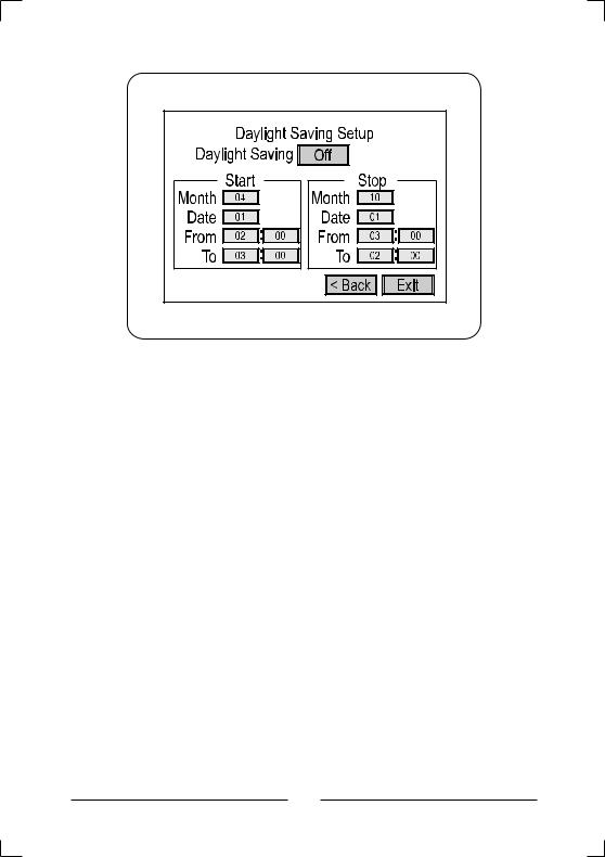
<Figure 9 > Time, Date Setup, second screen.
•Daylight Saving : If you are in an area that does not have Daylight Saving (Summer) Time, set this option to Off. When you set this selection to On, you must set the start and stop dates and times.
•Start : Set the Month and Date that your area begins Daylight Saving time. Unless there is an unusual situation, you will not need to set From and To times.
•Stop : Set the Month and Date that your area ends Daylight Saving time. Unless there is there is an unusual situation, you will not need to set From and To times.
•< Back : Selecting this takes you back to the first Time, Date Setup Screen.
•Exit : Selecting this saves your settings and exits the Time, Date Setup screens.
12
Camera Access Setup
ENGLISH
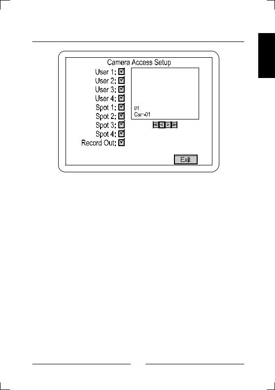
< Figure 10 > Camera Access Setup screen.
The Camera Access Setup screen allows you to assign which cameras different users will have access to and which cameras can be displayed on the Spot (auxiliary) monitors. You can also designate whether a camera can be recorded.
•<< : Goes to Camera 1
•< : Goes back one camera
•> : Goes forward one camera.
•>> : Goes to Camera 9
• : An
: An  next to an item activates the camera for that output.
• |
O : An O deactivates the camera. |
• |
Exit : Saves your changes and returns to the Main Menu. |
13
Camera Title Setup
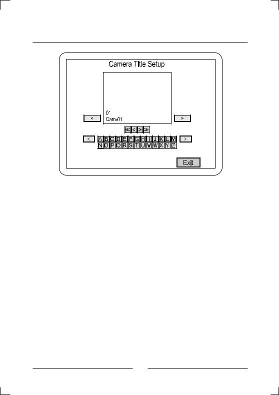
< Figure 11 > Camera Title Setup screen.
The Camera Title Setup screen allows you to enter titles for each camera. Clicking on the letters and characters enters them in the camera title. Each camera title can have a maximum of 24 characters.
•Top < : Moves the cursor left.
•Top > : Moves the cursor right.
•Middle << : Goes to Camera 1.
•Middle < : Goes back one camera.
•Middle > : Goes forward one camera.
•Middle >> : Goes to Camera 9.
•Bottom < : Changes the keyboard characters to the previous set.
•Bottom > : Changes the keyboard characters to the next set.
14
• Keyboard Character Set 1 : A to Z (upper case) |
|
||
ENGLISH |
|||
• Keyboard Character Set 2 : a to z (lower case) |
|||
|
|||
• Keyboard Character Set 3 : BLANK ! " # $ % & ' ( ) * +, - . / 0 to 9 |
|
||
• Keyboard Character Set 4 |
: : ; < = > ? [ \ ] ^ _ ' { I } ~ |
|
|
|
|||
• Keyboard Character Set 5 |
: À Á Â Ä Ç È É Ê Ë Ì Í Î Ï Ñ Ò Ó Ô Ö Ù Ú |
|
|
Û Ü ß à á â |
|
|
|
• Keyboard Character Set 6 |
: ä ç è é ê ë ì í î ï ñ ò ó ô ö ù ú û ü |
|
|
• Exit : Saves your changes and returns to the Main Menu.
Camera Sequence Setup
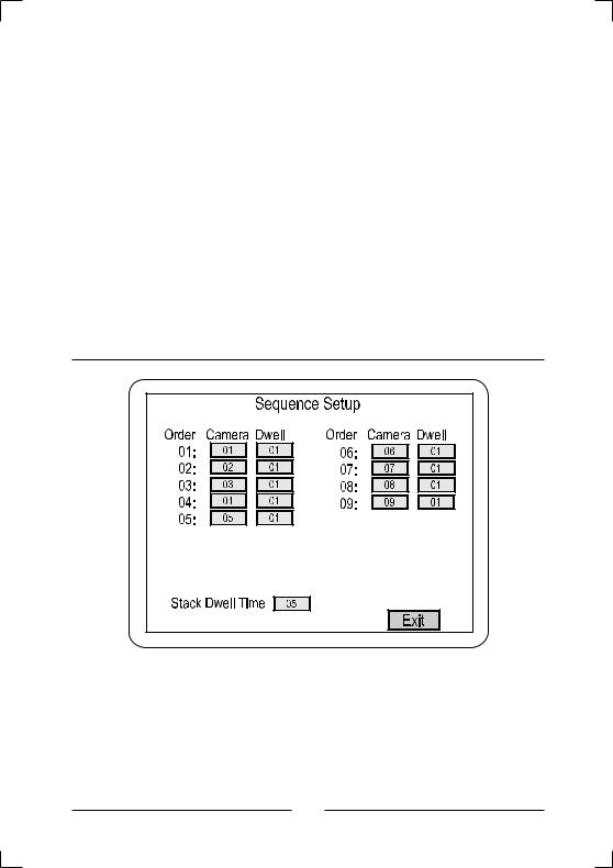
< Figure 12 > Camera Sequence Setup screen.
This screen allows you to set the order in which the cameras appear when the multiplexer is in sequence mode. You can also set the how long each camera will display from Off to 99 seconds.
15
Enter the camera number under the Camera column and the display time under Dwell. You can also set the Stack Dwell Time, which is the length of time each group of cameras will display.
• Exit : Saves your changes and returns to the Main Menu.
Alarm Setup
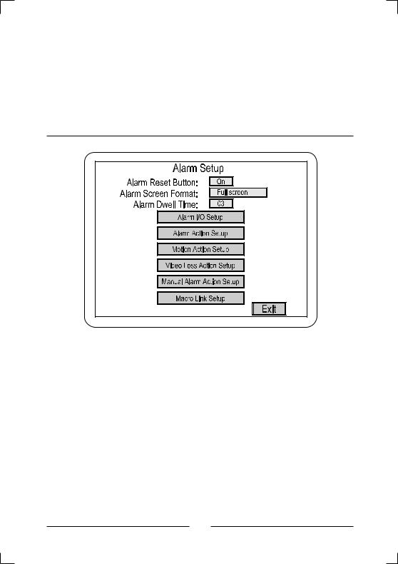
< Figure 13 > Alarm Setup screen.
The Alarm Setup screen allows you to enter six alarm submenus.
•Alarm Reset Button : Setting this to On allows users to clear alarm events using the front panel buttons or the Pop Up menu. Setting it to Off requires the user to enter the Setup Menus to clear alarm events.
•Alarm Screen Format : This sets the display mode the multiplexer will use when an alarm occurs. There are four possible settings: Full, 2x2, 2x2 Associated and Unchanged.
16
 Loading...