


FlashGuard 2000B Medium Intensity Lighting System
Troubleshooting Guide
Table of Contents
Flashhead (Strobe) Troubleshooting Flowchart |
pg. 2 |
Multiple Strobe Troubleshooting Flowchart |
pg. 3 |
Flashhead Problems |
pg. 4 |
Multiple Strobe Problems |
pg. 7 |
Flashhead Isolation Test |
pg. 9 |
Power Supply Isolation Test |
pg. 10 |
Status Indicators |
pg. 11 |
Tools Required |
pg. 11 |
Recommended Spare Parts |
pg. 12 |

FlashGuard 2000B Troubleshooting Guide
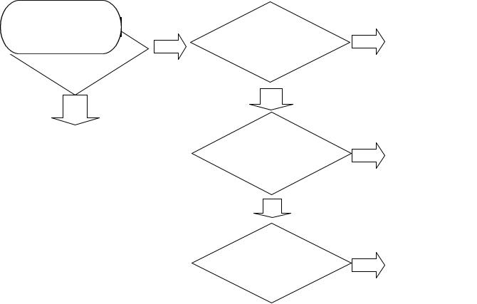
Flashhead (Strobe) Problems
START |
|
|
|
|
Flashhead |
|
Are all of |
|
|
works in at |
No |
|
||
the LEDs |
No |
|||
least one |
|
|||
|
OFF? |
|
||
mode? |
|
|
||
|
|
|
||
|
|
Yes |
|
|
Yes |
|
Section 1, pg. 4 |
|
Day mode
strobe is
OK, Night Yes Section 4, pg. 5 strobe out?
No |
|
|
Night mode |
|
Section 5, pg. 5 |
strobe is OK, |
Yes |
|
Day strobe out? |
|
|
No
Strobe won’t
switch from day Yes Section 6, pg. 6 to night mode?
No
Strobe flashing
too fast or too Yes Section 7, pg. 7 slow?
No
Night mode
strobe too Yes Section 8, pg. 8 bright?
Control |
|
Control |
|
Power ON, |
|
||
|
Power and |
||
High Voltage |
No |
||
High Voltage |
|||
OFF? |
|||
|
Both ON ? |
||
|
|
||
Yes |
|
Yes |
|
|
|
||
Section 2, pg. |
|
Section 3, pg. 5 |
|
|
|
Page 2
FlashGuard 2000B Troubleshooting Guide
Multiple Strobe Problems
|
START |
|
Strobes are |
|
Only one strobe |
No |
|
|
flashing out of |
||
|
is acting |
||
|
|
sync. |
|
|
unusual? |
|
|
|
|
|
|
|
Yes |
|
No |
|
|
|
|
. |
Go to “Strobe problems” |
|
Strobes have a |
|
‘double flash’ or |
||
flowchart, preceding |
|
||
|
|
are flashing faster |
|
|
page |
|
|
|
|
than 40 FPM? |
|
|
|
|
|
|
|
|
No |
|
|
|
Master switches to |
|
|
|
night, but slaves |
|
|
|
stay in day mode? |
Yes |
Section 9, pg. 8 |
Yes |
Section 10, pg. 8 |
Yes |
Section 11, pg. 8 |
Page 3
FlashGuard 2000B Troubleshooting Guide
FLASHHEAD (STROBE) PROBLEMS
Section 1 Flashhead does not operate in any mode, no LED’s on.
Possible Cause: |
Input power incorrect. |
Diagnostic Test: |
Measure input power – it should be 120 VAC ±10%. |
Corrective Action: Supply correct input power. |
|
Possible Cause: |
Power supply interlock switch not engaged. |
Diagnostic Test: |
Press the power supply interlock switch and hold it down. |
Corrective Action: Close the unit – the system should operate properly. |
|
Possible Cause: |
Blown F1 (4 Amp) fuse, or transformer (630mA) fuse. |
Diagnostic Test: |
Remove all three circuit boards and check for damage. Remove the |
|
photocell wiring from TB1-1 and TB1-2. Perform “Flashhead Isolation Test” |
(pg. 9) and check for improper resistances. Leave the flashhead cable disconnected, replace the fuse and apply power. Reconnect the strobe cable, the photocell wiring, and the circuit boards one by one to determine which one will blow the fuse.
Corrective Action: Replace the defective component.
Section 2 Flashhead does not operate in any mode, control power indicator on, high-voltage neon lamp off.
Possible Cause: Flashhead interlock switch not engaged.
Diagnostic Test: Remove the flashhead wires TB2-5 and TB2-6 (gray and white), and measure resistance between them – it should be less than 5Ω.
Corrective Action: Re-seat the flashhead cover, making sure the interlock switch engages when the cover is closed. If the system still does not have continuity between TB2-5 and TB2-6, replace the flashhead interlock switch and/or inspect the strobe cable for damage.
Possible Cause: Relay K1 not energizing.
Diagnostic Test: When the interlock switches are engaged, the K1 relay should energize. If not, measure for 120 VAC across the relay coil. Alternatively, remove the connectors and check resistance across the K1 coil – it should be 300Ω.
Corrective Action: Replace the K1 relay.
Possible Cause: Faulty high-voltage board.
Diagnostic Test: Visually check the traces on the high-voltage board. Check for any shorted diodes. Use diode check function on multimeter if available.
Corrective Action: Replace the high-voltage board.
Page 4
 Loading...