


DOLPHIN 9950
Table of contents
 Loading...
Dolphin® 9900 Mobile Computers
Dolphin 9900
Dolphin 9950
Dolphin 9951
with Windows Mobile
®
User’s Guide
6.1

Disclaimer
Honeywell International Inc. (“HII”) reserves the right to make changes in specifications and other
information contained in this document without prior notice, and the reader should in all cases consult HII
to determine whether any such changes have been made. The information in this publication does not
represent a commitment on the part of HII.
HII shall not be liable for technical or editorial errors or omissions contained herein; nor for incidental or
consequential damages resulting from the furnishing, performance, or use of this material.
This document contains proprietary information that is protected by copyright. All rights are reserved. No
part of this document may be photocopied, reproduced, or translated into another language without the
prior written consent of HII.
Web Address: www.honeywellaidc.com
Trademarks
Dolphin, Dolphin RF, HomeBase, Mobile Base, and QuadCharger are trademarks or registered
trademarks of Hand Held Products, Inc. or Honeywell International Inc.
Microsoft, Windows, Windows Mobile, Windows CE, Windows NT, Windows 2000, Windows ME,
Windows XP, ActiveSync, Outlook, and the Windows logo are trademarks or registered trademarks of
Microsoft Corporation.
Other product names mentioned in this manual may be trademarks or registered trademarks of their
respective companies and are the property of their respective owners.
Patents
Please refer to the product packaging for a list of patents.
Other Trademarks
The Bluetooth trademarks are owned by Bluetooth SIG, Inc., U.S.A. and licensed to Honeywell.
©2008–2010 Honeywell International Inc. All rights reserved.

Table of Contents
Chapter 1 - Agency Information
Label Locations....................................................................................................................1-1
LED Safety Statement .........................................................................................................1-2
Infrared LED Safety Statement ............................................................................................1-2
UL and C-UL Statement.......................................................................................................1-2
Approvals by Country...........................................................................................................1-3
R&TTE Compliance Statement—802.11b/g, Bluetooth, and/or GSM..................................1-3
Dolphin RF Terminal—802.11b/g, Bluetooth, and/or GSM..................................................1-4
For European Community Users .........................................................................................1-4
Waste Electrical and Electronic Equipment Information ......................................................1-4
ANATEL ...............................................................................................................................1-5
Chapter 2 - Getting Started
Out of the Box ......................................................................................................................2-1
Today Screen.......................................................................................................................2-3
Navigation Bar .....................................................................................................................2-3
Command Bar......................................................................................................................2-4
Icons in the Navigation Bar ..................................................................................................2-5
Pop-Up Menus .....................................................................................................................2-6
Chapter 3 - Hardware Overview
Standard Configurations for the 9900 ............................................................................3-1
Standard Configuration for the 9950 ..............................................................................3-1
Standard Configuration for the 9951 ..............................................................................3-1
Peripherals for the 9900, 9950, and 9951............................................................................3-2
Accessories for the 9900, 9950, and 9951 ..........................................................................3-3
Front Panel: 9900, 9950, and 9951 .....................................................................................3-4
Front Panel Features for the 9900, 9950, and 9951 ......................................................3-5
Back Panel: 9900 ................................................................................................................3-6
Back and Side Panels: 9950 and 9951................................................................................3-7
Side Panel .....................................................................................................................3-7
Back Panel ....................................................................................................................3-8
Back Panel Features for the 9900, 9950, and 9951 ...........................................................3-9
Side Panels: 9900, 9950, and 9951...................................................................................3-10
Left Side .......................................................................................................................3-10
Right Side ....................................................................................................................3-10
Installing a Memory Card .............................................................................................3-11
Bottom Panel: 9900, 9950, and 9951 ................................................................................3-12
I/O Connector...............................................................................................................3-12
Using the Touch Panel.......................................................................................................3-13
Installing a Screen Protector ........................................................................................3-13
Healthcare Housing ...........................................................................................................3-14
iii

Batteries ............................................................................................................................ 3-14
Main Battery Pack........................................................................................................ 3-14
Internal Backup Battery ...............................................................................................3-15
Managing Battery Power .............................................................................................3-16
Checking Battery Power .............................................................................................. 3-17
Resetting the Terminal ...................................................................................................... 3-18
Soft Reset (Warm Boot)............................................................................................... 3-18
Hard Reset (Cold Boot) ...............................................................................................3-18
Suspend Mode .................................................................................................................. 3-18
Chapter 4 - Using the Scan Image Engine
Overview.............................................................................................................................. 4-1
Angled Imaging.............................................................................................................. 4-1
Image Engine Specifications ............................................................................................... 4-1
Available Laser Engines ...................................................................................................... 4-2
Laser Specifications ............................................................................................................4-2
Supported Bar Code Symbologies ..................................................................................... 4-3
Decoding ............................................................................................................................. 4-4
To Decode a Bar Code.................................................................................................. 4-4
Aiming Options ..............................................................................................................4-5
Capturing Images ................................................................................................................4-6
Taking an Image............................................................................................................ 4-6
Uploading Images.......................................................................................................... 4-7
Chapter 5 - Using the Keyboards
Available Keyboards............................................................................................................ 5-1
Keyboard Combinations ................................................................................................5-1
Common Buttons........................................................................................................... 5-2
Using the Function Keys...................................................................................................... 5-2
Using the Modifier Keys ...................................................................................................... 5-3
Using the Navigation Keys .................................................................................................. 5-3
Sticky Key Functionality....................................................................................................... 5-4
35-Key Alpha/Numeric Keyboard ........................................................................................ 5-5
35-Key Keyboard Combinations.................................................................................... 5-6
43-Key Alpha/Numeric Keyboard ........................................................................................ 5-8
43-Key Keyboard Combinations.................................................................................... 5-9
56-Key Full Alpha/Numeric Keyboard ........................................................................... 5-11
56-Key Keyboard Combinations.................................................................................. 5-12
General Windows Keyboard Shortcuts ............................................................................. 5-14
Chapter 6 - System Settings
Overview.............................................................................................................................. 6-1
Personal Tab ....................................................................................................................... 6-2
Buttons........................................................................................................................... 6-3
Input............................................................................................................................... 6-4
Menus............................................................................................................................ 6-5
iv

System Tab ......................................................................................................................... 6-7
About .............................................................................................................................6-8
Backlight ........................................................................................................................ 6-8
Certificates..................................................................................................................... 6-9
ClearType Tuner............................................................................................................ 6-9
Clock & Alarms .............................................................................................................. 6-9
Encryption.................................................................................................................... 6-10
Error Reporting ............................................................................................................ 6-10
External GPS............................................................................................................... 6-10
Memory........................................................................................................................ 6-11
Power...........................................................................................................................6-12
Regional Settings......................................................................................................... 6-13
Remove Programs....................................................................................................... 6-13
Screen .........................................................................................................................6-14
WAN Info .....................................................................................................................6-15
Chapter 7 - Communication
Connections Tab .................................................................................................................7-1
Using the IrDA Port.............................................................................................................. 7-2
IrDA Port Location .........................................................................................................7-2
Sending Data................................................................................................................. 7-2
Receiving Data ..............................................................................................................7-3
Connections Manager ......................................................................................................... 7-4
To Access the Connections Manager............................................................................ 7-4
Task Tab........................................................................................................................7-4
Advanced Tab................................................................................................................ 7-5
Dolphin Wireless Manager .................................................................................................. 7-6
Dolphin Wireless Manager Window............................................................................... 7-6
Enabling the Radios....................................................................................................... 7-6
Accessing Radio Configuration Utilities......................................................................... 7-7
ActiveSync Communication................................................................................................. 7-8
Installing Additional Software ............................................................................................ 7-10
Adding Programs to the Terminal Using ActiveSync ...................................................7-10
Adding Programs Directly from the Internet................................................................. 7-11
9900/9950/9951 COM Port Assignment Table.................................................................. 7-12
Chapter 8 - Working with GSM
Overview.............................................................................................................................. 8-1
Quad Band Antenna ...................................................................................................... 8-1
SIM Card Installation ...........................................................................................................8-2
Enabling the GSM Radio ..................................................................................................... 8-4
v

Voice Communication.......................................................................................................... 8-5
Audio Modes.................................................................................................................. 8-5
Volume Control.............................................................................................................. 8-5
Accessing the Dialer Window ........................................................................................ 8-5
Dialing............................................................................................................................ 8-5
Sending Calls................................................................................................................. 8-6
Ending Calls................................................................................................................... 8-6
Keyboard Combinations for Calls .................................................................................. 8-6
View Options.................................................................................................................. 8-6
Setup Options...................................................................................................................... 8-7
Data Communication ........................................................................................................... 8-8
Establishing Data Communication................................................................................. 8-8
Ending the Data Connection........................................................................................ 8-10
Roaming ............................................................................................................................ 8-11
Chapter 9 - Working with the Bluetooth Radio
Enabling the Bluetooth Radio .............................................................................................. 9-1
Connecting to Other Bluetooth Devices .............................................................................. 9-2
Pairing and Trusted Devices ............................................................................................... 9-4
Types of Devices and Services ........................................................................................... 9-5
Connecting to Bluetooth Printers......................................................................................... 9-6
Connecting to Bluetooth Headsets ...................................................................................... 9-6
Transferring Files................................................................................................................. 9-7
Making the Terminal Discoverable ...................................................................................... 9-8
Selecting COM Ports ........................................................................................................... 9-8
Chapter 10 - Working with GPS
Overview............................................................................................................................ 10-1
Assisted GPS Support....................................................................................................... 10-1
Powering the GPS Module ................................................................................................ 10-1
Communication Ports ........................................................................................................ 10-1
Selecting the Port ........................................................................................................10-1
COM7 ..........................................................................................................................10-2
GPS Intermediate Driver.............................................................................................. 10-2
GPS Demo ........................................................................................................................10-2
Chapter 11 - Dolphin HomeBase Device
Overview............................................................................................................................ 11-1
Parts and Functions........................................................................................................... 11-2
Power ................................................................................................................................ 11-4
Serial Connector................................................................................................................ 11-5
Charging the Main Battery................................................................................................. 11-6
To Power a Terminal and Charge its Main Battery...................................................... 11-6
Charging a Spare Battery in the Auxiliary Battery Well ...............................................11-6
Communication.................................................................................................................. 11-7
Connecting the Communication Cables ......................................................................11-7
Establishing Communication .......................................................................................11-7
vi

Communicating with the Dolphin Terminal ........................................................................ 11-8
Verifying Data Transfer................................................................................................ 11-8
RS-232 Communications Cables ...................................................................................... 11-8
RS-232 Pin Configuration............................................................................................ 11-9
Mounting............................................................................................................................ 11-9
Desk Mounting........................................................................................................... 11-10
Wall Mounting............................................................................................................ 11-10
Chapter 12 - Dolphin Mobile Base Device
Overview............................................................................................................................ 12-1
Front Panel ........................................................................................................................ 12-2
Bottom Panel ..................................................................................................................... 12-3
Powering the Dolphin Terminal ......................................................................................... 12-3
Charging the Dolphin Terminal.......................................................................................... 12-4
Mounting............................................................................................................................ 12-4
Power ................................................................................................................................ 12-5
Establishing Communication ............................................................................................. 12-6
Connecting the Communication Cables ......................................................................12-6
Establishing ActiveSync Communication..................................................................... 12-6
Chapter 13 - Dolphin ChargeBase Device
Overview............................................................................................................................ 13-1
Parts and Functions........................................................................................................... 13-2
Supplying Power................................................................................................................ 13-3
Inserting and Removing Terminals.................................................................................... 13-4
Charging Terminals ........................................................................................................... 13-4
Mounting............................................................................................................................ 13-5
Chapter 14 - Dolphin QuadCharger Device
Overview............................................................................................................................ 14-1
Parts and Functions........................................................................................................... 14-2
Supplying Power................................................................................................................ 14-3
Inserting and Removing Battery Packs ............................................................................. 14-4
Charging Batteries............................................................................................................. 14-4
Using the Battery Analyzer ................................................................................................ 14-5
Mounting............................................................................................................................ 14-6
Desk Mounting............................................................................................................. 14-6
Wall Mounting.............................................................................................................. 14-7
Troubleshooting.................................................................................................................14-8
Chapter 15 - Customer Support
Product Service and Repair............................................................................................... 15-1
Online Product Service and Repair Assistance........................................................... 15-1
Technical Assistance......................................................................................................... 15-2
Online Technical Assistance........................................................................................ 15-2
Limited Warranty ...............................................................................................................15-3
How to Extend Your Warranty ..................................................................................... 15-4
vii

viii
1
Compliance Label
Compliance Label
LASER LIGHT. DONOTSTAREINTOBEAM.
CLASS 2 L AS E R PRODUCT. 1.0 mW MAX
OUTP UT: 650nM. IEC 60825-1: 1993+A1+A2
Complies with 21 CFR 1040.10 and 1040.11
exc ept fo r dev ia tions purs u ant to L as e r
Notice No. 50, dated June 24, 2007.
ScanRate
=35+/- 5Scans/Sec.
LASER LIGHT. DO NOT STARE INTO BEAM.
CLASS 2 LASER PRODUCT
1.0 mW MAX OUTPUT: 650nM
IEC60825-1: 1993+A1+A2
Complies with 21 CFR 1040.10 and 1040.11
except for deviations pursuant to Laser
Notice No. 50, dated June 24, 2007.
SE1200 Laser Scan Engines Image Engines with Integrated Laser Aimers
!
Agency Information
Dolphin 9900, 9950, and 9951 terminals meet or exceed the requirements of all applicable standards
organizations for safe operation. However, as with any electrical equipment, the best way to ensure safe
operation is to operate them according to the agency guidelines that follow. Please read these guidelines
carefully before using your Dolphin terminal.
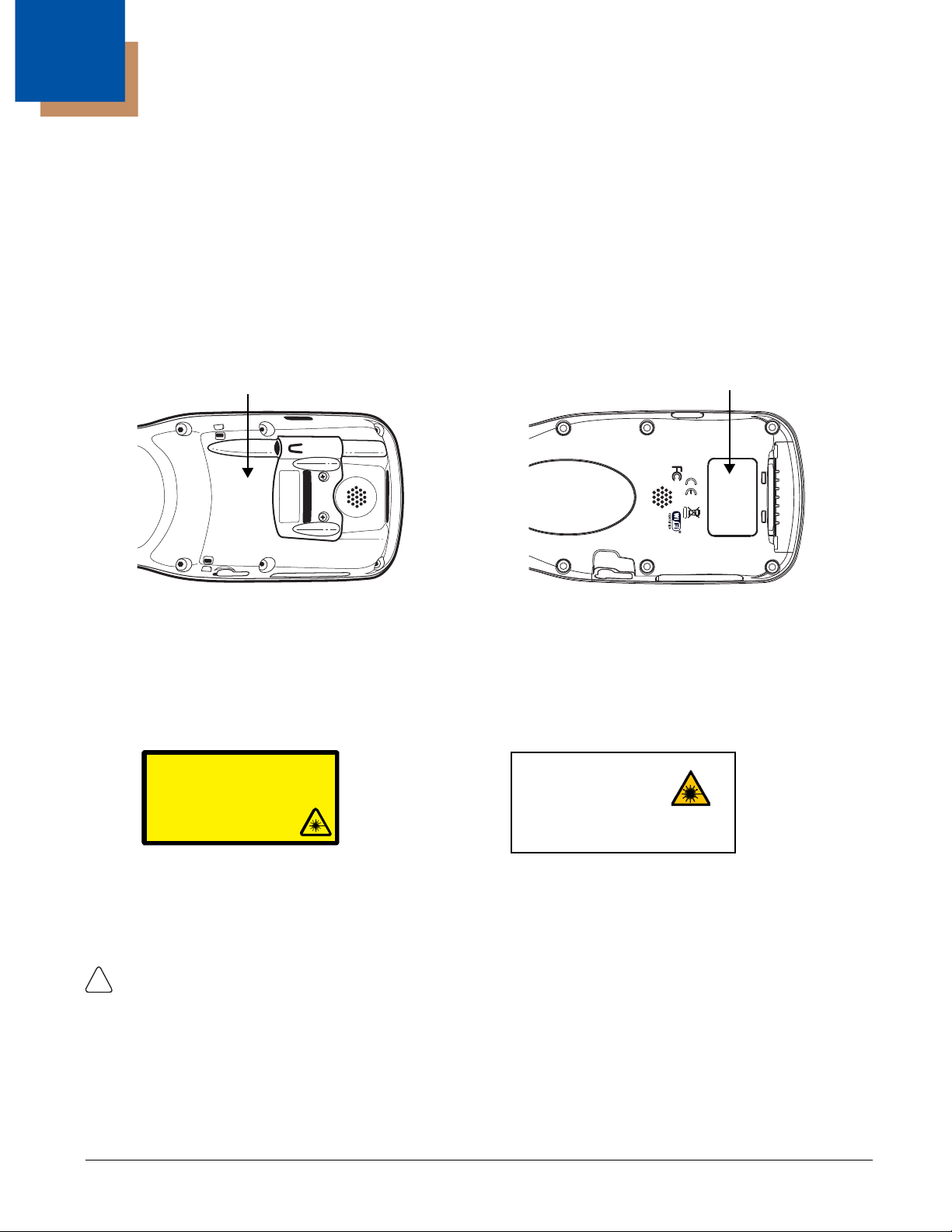
Label Locations
Dolphin 9900 Dolphin 9950 & 9951
Laser Safety Label
If the following label is attached to your product, it indicates the product contains a laser engine or laser
aimer:
Laser Eye Safety Statement: This device has been tested in accordance with and complies with
IEC60825-1: 1993+A1+A2 and 21 CFR 1040.10 and 1040.11, except for deviations pursuant to Laser
Notice No. 50, dated June 24, 2007. LASER LIGHT, DO NOT STARE INTO BEAM, CLASS 2 LASER
PRODUCT, 1.0 mW MAX OUTPUT: 650nM.
Caution - use of controls or adjustments or performance of procedures other than those specified
herein may result in hazardous radiation exposure.
1 - 1

LED Safety Statement
!
The LED output on this device has been tested in accordance with IEC60825-1 LED safety and certified
to be a Class 1 LED device.
The maximum power outputs for each diode are as follows:
• Illumination LED: 194.0 uW, wavelength: 626nm+/-30nm
• Aimer laser (5300 engine): 360.1 uW, wavelength: 655nm
• Aimer LED (5100 engine): 81.6 uW, wavelength: 526nm+/-30nm
• Laser (9951 models): <1.5 mW, wavelength: 650nm, scans/second (bidrectional): 35 (+/- 5)
Infrared LED Safety Statement
Caution - Do not view directly with optical instruments.
The maximum power outputs for the IR LED is 145.1 uW. LEDs are pulsed at a frequency of 115,200
Hz with a duty cycle of 18.75% where the “ON” time of a single pulse is 1.6275 x 10
-6
seconds.
UL and C-UL Statement
UL and C-UL listed: UL60950-1 and CSA C22.2 No. 60950-1-03, ISA 12.12.01:2007
CAN/CSA: C22.2 No. 213-M1987
The following notes apply to 99XXXXX-XXXXXXI units (Hazardous Location rated. See Approvals by
Country on page 1-3.).
Note: This equipment is suitable for use in Class 1, Division 2, Groups A, B, C, D, Class II, Division 2
Group G, Class III or non-hazardous locations only.
Note: Maximum operating ambient temperature rating 50°C.
Note: Underwriters Laboratories Inc. (UL) has not tested the performance or reliability of the global
positioning system (GPS) hardware, GPS operating software or other GPS-related aspects of this
product. UL has only tested for the explosion, fire, shock and casualty hazards required by the
applicable hazardous locations standards. UL certification does not cover the performance or
reliability of the GPS hardware, GPS operating software or other GPS-related aspects of this
product. UL makes no representations, warranties or certifications whatsoever regarding the
performance or reliability of any GPS-related functions of this product.
1 - 2

Approvals by Country
Country EMC, Radio, & SAR Safety
U.S.A. FCC Part 15, Subpart C, 15.247
FCC Part 15, Subpart B
FCC Part 22H
FCC Part 24H
FCC SAR OET 65 Supplement C
Canada ICES-003 (Class B)
RSS 132
RSS 133
RSS 210
European Community/CE EN300328-1/2
EN55022:1998+A1:2000+A2:2003
EN55024:1998+A1:2001+A2:2003
EN301489-1
EN301489-7
EN301489-17
EN300328
3GPPTS 51.010-1
ETSI EN301511
EN301511
EN60360 June 2001
EN50361 June 2001
EN50371 June 2001
UL60950-1
*Hazardous Location:
ISA 12.12.01:2007
CSA C22.2 No. 60950-1-03
*Hazardous Location:
CAN/CSA C22.2 No. 213-M1987
EN60950-1:2000
EN60950-1:2001+A11:2004
EN60825-1:1994+A1:2002+A2:2001
*Applies to 99XXXXX-XXXXXXI units.
This Class 2 Laser Product is in accordance with the requirements of IEC 60825-1 Ed. 1.2 Clause 6.2(a).
R&TTE Compliance Statement—802.11b/g, Bluetooth, and/or GSM
Dolphin RF terminals are in conformity with all essential requirements of the R&TTE Directive (1999/5/
EC).
This product is marked with in accordance with the Class II product requirements specified in
the R&TTE Directive. In addition, this product complies to 2006/95/EC Low Voltage Directive when
supplied with the recommended power supply. Honeywell shall not be liable for use of our product with
equipment (i.e., power supplies, personal computers, etc.) that is not CE marked and does not comply
with the Low Voltage Directive.
The equipment is intended for use throughout the European Community; PAN European Frequency
Range: 2.402–2.480 GHz. Restrictions for use in France are as follows:
• Indoor use: Maximum power (EIRP*) of 100 mW for the entire 2.400–2.4835 GHz
• Outdoor use: Maximum power (EIRP*) of 100 mW for the 2.400–2.454 GHz band & maximum power
(EIRP*) of 10 mW for the 2.454–2.483 MGHz band.
For further information, please contact:
Honeywell Imaging & Mobility Europe BV
Nijverheidsweg 9
5627 BT Eindhoven
The Netherlands
1 - 3

Dolphin RF Terminal—802.11b/g, Bluetooth, and/or GSM
This device complies with Part 15 of the FCC Rules. Operation is subject to the following two conditions:
(1) this device may not cause harmful interference, and (2) this device must accept any interference
received, including interference that may cause undesired operation.
This equipment has been tested and found to comply with the limits for a Class B digital device pursuant
to Part 15 of the FCC Rules. These limits are designed to provide reasonable protection against harmful
interference in a residential installation. This equipment generates, uses, and can radiate radio frequency
energy and, if not installed and used in accordance with the instructions, may cause harmful interference
to radio communications. However, there is no guarantee that interference will not occur in a particular
installation. If this equipment does cause harmful interference to radio or television reception, which can
be determined by turning the equipment off and on, the user is encouraged to try to correct the
interference by one or more of the following measures:
• Reorient or relocate the receiving antenna.
• Increase the separation between the equipment and receiver.
• Connect the equipment into an outlet on a circuit different from that to which the receiver is connected.
• Consult the dealer or an experienced radio/TV technician for help.
If necessary, the user should consult the dealer or an experienced radio/television technician for
additional suggestions. The user may find the following booklet helpful: “Something About Interference.”
This is available at FCC local regional offices. Our company is not responsible for any radio or television
interference caused by unauthorized modifications of this equipment or the substitution or attachment of
connecting cables and equipment other than those specified by our company. The correction is the
responsibility of the user. Use only shielded data cables with this system.
In accordance with FCC 15.21, changes or modifications not expressly approved by the party responsible
for compliance could void the user’s authority to operate the equipment.
CAUTION! Any changes or modifications not expressly approved by the grantee of this device could void
the user's authority to operate the equipment.
Canadian Compliance
This Class B digital apparatus complies with Canadian ICES-003. Operation is subject to the following
two conditions: (1) this device may not cause harmful interference, and (2) this device must accept any
interference received, including interference that may cause undesired operation.
To prevent radio interference to the licensed service, this device is intended to be operated indoors and
away from windows to provide maximum shielding. Equipment (or its transmit antenna) installed outdoors
is subject to licensing.
Cet appareil numérique de la Classe B est conforme à la norme NMB-003 du Canada.
For European Community Users
Honeywell complies with Directive 2002/96/EC OF THE EUROPEAN PARLIAMENT AND OF THE
COUNCIL of 27 January 2003 on waste electrical and electronic equipment (WEEE).
Waste Electrical and Electronic Equipment Information
This product has required the extraction and use of natural resources for its production. It may contain
hazardous substances that could impact health and the environment, if not properly disposed.
1 - 4

In order to avoid the dissemination of those substances in our environment and to diminish the pressure
1866-08-2760
on the natural resources, we encourage you to use the appropriate take-back systems for product
disposal. Those systems will reuse or recycle most of the materials of the product you are disposing in a
sound way.
The crossed out wheeled bin symbol informs you that the product should not be disposed of along
with municipal waste and invites you to use the appropriate separate take-back systems for product
disposal.
If you need more information on the collection, reuse, and recycling systems, please contact your local or
regional waste administration.
You may also contact your supplier for more information on the environmental performances of this
product.
ANATEL
Este produto está homologado pela ANATEL, de acordo com
os procedimentos regulamentados pela Resolução 242/2000, e
atende aos requisitos técnicos aplicados.
Para maiores informações, consulte o site da ANATEL -
www.anatel.gov.br.
Este equipamento opera em caráter secundário, isto é, não tem
direito a proteção contra interferência prejudicial, mesmo de
estações do mesmo tipo, e não pode causar interferência a sistemas operando em caráter primário.
Pacemakers, Hearing Aids and Other Electrically Powered Devices
Most manufacturers of medical devices adhere to the IEC 601-1-2 standard. This standard requires
devices to operate properly in an EM Field with a strength of 3V/m over a frequency range of 26 to
1000MHz. The maximum allowable field strength emitted by the Dolphin terminal is 0.3V/m according to
Subpart B of Part 1 of the FCC rules. Therefore, the RF from the Dolphin terminal has no effect on medical
devices that meet the IEC specification.
Microwaves
The radio in the Dolphin RF terminal operates on the same frequency band as a microwave oven.
Therefore, if you use a microwave within range of the Dolphin RF terminal you may notice performance
degradation in your wireless network. However, both your microwave and your wireless network will
continue to function. The Dolphin Batch terminal does not contain a radio, and therefore, is not affected
by microwave ovens.
1 - 5

1 - 6
2
!
!
!
!
!
!
Getting Started
Out of the Box
Verify that the carton contains the following items:
• Dolphin 9900 or 9950 or 9951 mobile computer (the terminal)
• Main battery pack (7.4v Li-ion)
• Microsoft Getting Started CD
• Q u i c k S t a r t G u i d e
Note: If you ordered accessories for your terminals, verify that they are also included with the order.
Be sure to keep the original packaging in the event that the Dolphin terminal should need to be returned
for service. For details, see Product Service and Repair on page 15-1.
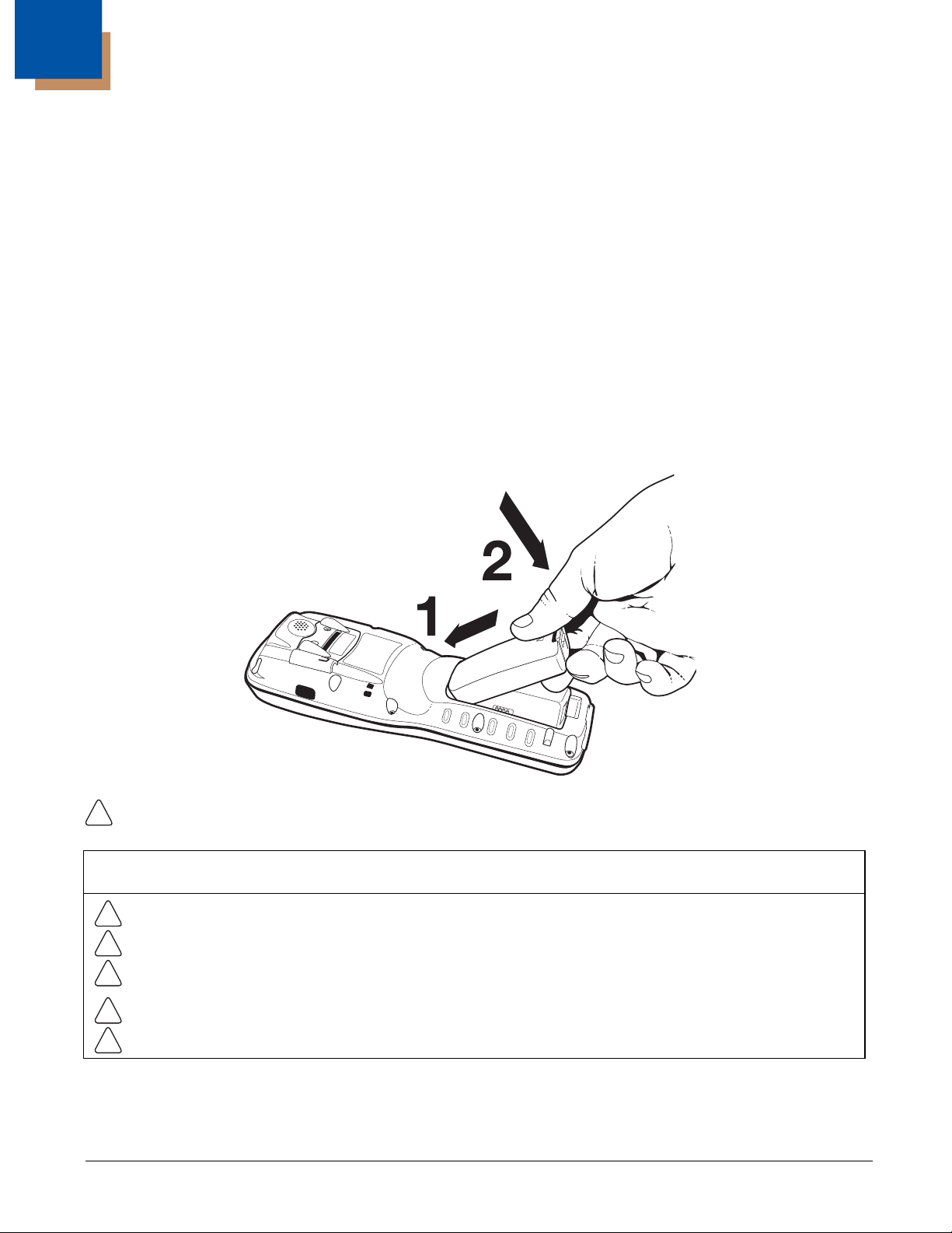
Step 1. Install the Main Battery Pack
We recommend use of Honeywell Li-Ion battery packs. Use of any non-Honeywell battery may result in
damage not covered by the warranty.
Note: The following warnings apply to 99XXXXX-XXXXXXI units (Hazardous Location rated. See Approvals by
Country on page 1-3.).
Replace only with battery pack type 200002586 manufactured by Honeywell International Incorporated.
Warning: Explosion Hazard. Charge or replace the battery only in an area known to be non-hazardous.
Warning: Explosion Hazard. Do not replace components unless power has been switched off or the area
is known to be non-hazardous.
Warning: Substitution of any components may impair suitability.
Warning: Explosion Hazard. Do not use external connectors in areas known to be hazardous.
2 - 1
Step 2. Charge the Main and Backup Batteries
!
!
!
!
!
!
The power supply for Dolphin terminals consists of two types of battery power: the main battery pack
installed on the back panel and the backup battery that resides inside the terminal.
The main battery powers the terminal. The internal backup battery charges off the main battery and
maintains the application data stored in RAM memory for up to 30 minutes when the terminal’s main
battery pack is completely discharged or removed.
Before Initial Use
Terminals are shipped with both batteries discharged of all power. Charge the main battery pack
for a minimum of 4.5 hours before initial use.
Time to Charge
Initial charging time for the main battery pack is 4.5 hours and 8 hours for the internal backup
battery. Connect the terminal to one of the 9000 series charging peripherals to charge; see
Peripherals for the 9900, 9950, and 9951 on page 3-2.
We recommend use of Honeywell peripherals, power cables, and power adapters. Use of any non-Honeywell
peripherals, cables, or power adapters may cause damage not covered by the warranty.
Note: The following warnings apply to 99XXXXX-XXXXXXI units (Hazardous Location rated. See Approvals by
Country on page 1-3.).
Replace only with battery pack type 200002586 manufactured by Honeywell International Incorporated.
Warning: Explosion Hazard. Charge or replace the battery only in an area known to be non-hazardous.
Warning: Explosion Hazard. Do not replace components unless power has been switched off or the area
is known to be non-hazardous.
Warning: Substitution of any components may impair suitability.
Warning: Explosion Hazard. Do not use external connectors in areas known to be hazardous.
Step 3. Boot the Terminal
The terminal begins booting as soon as power is applied and runs by itself. Do NOT press any keys or
interrupt the boot process. Only tap the screen when prompted.
When the boot process is complete, the Today screen appears, and the terminal is ready for use.
Note: Because, the Today screen appears a number of times during the boot process, wait a few seconds before
tapping anything on the Today screen.
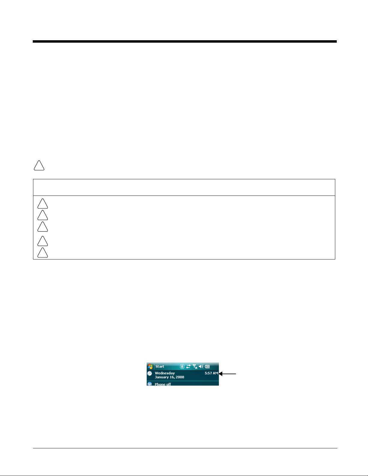
Step 4. Set the Time and Date
You need to re-set the time and date after every hard reset of the terminal. It is a good idea to set the time
and date before you begin using the device.
On the Today screen, tap the line that displays the time and date,
2 - 2
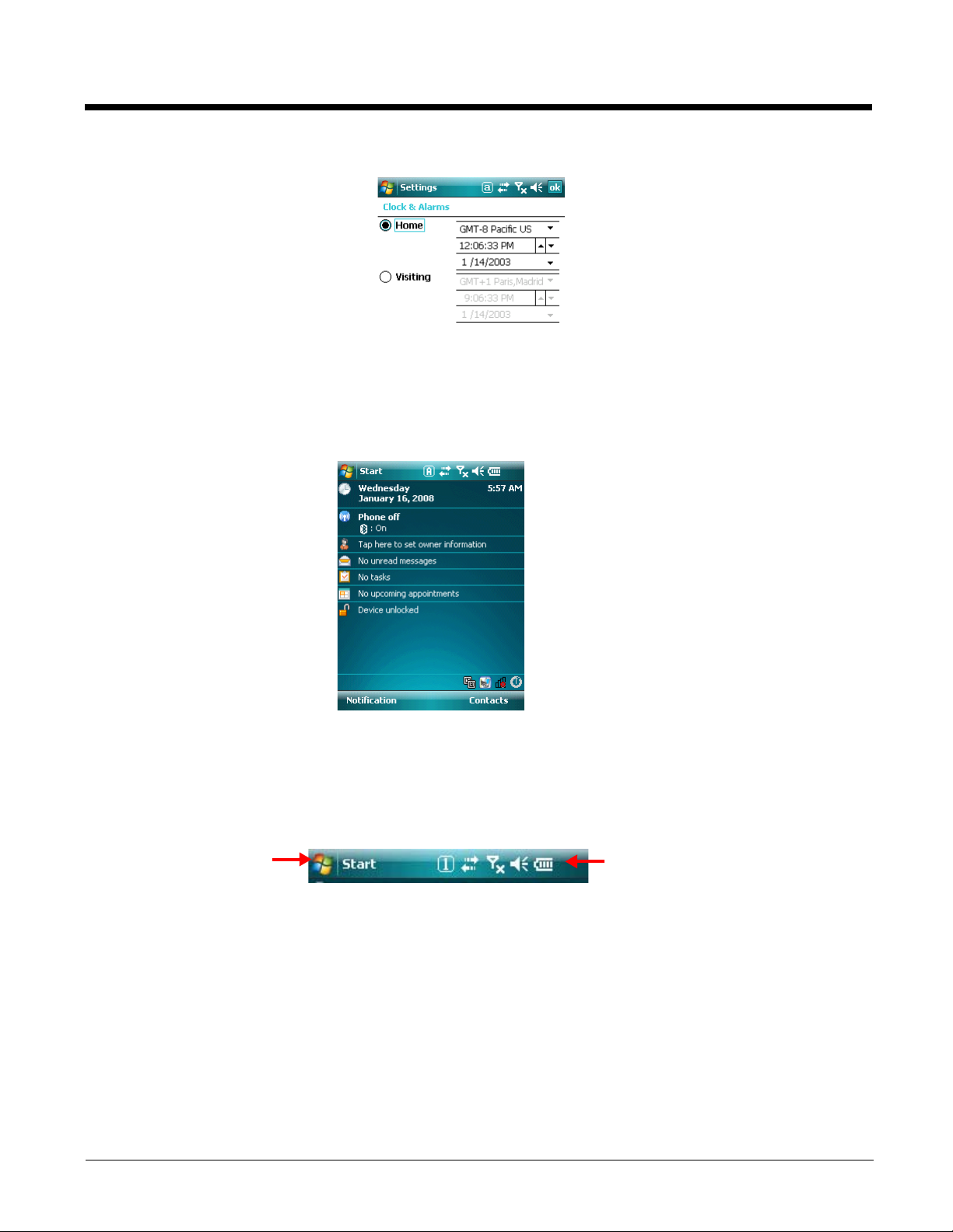
The Clock Settings screen appears.
Start menu: Grants
access to system
functions.
Icons here indicate
the status of various
system functions.
The time zone defaults to GMT-5 Eastern US; tap the arrow to the right of GMT-5 Eastern US to select
another time zone. Set the correct time and date in the remaining fields and tap
OK to save.
Today Screen
After the Dolphin terminal initializes the first time, you see the Today screen.
You can also display the Today screen anytime by tapping
Navigation Bar
The Navigation bar, located at the top of the screen, displays the active program and current time. It also
provides access to the Start menu, which allows you to open programs and access the system settings.
Start and then Today.
2 - 3

Command Bar
Menus change
according to the
open application.
The Task tray
displays icons for
programs running in
the background.
The Command bar is located at the bottom of application windows.
2 - 4

Icons in the Navigation Bar
Indicator Meaning
The terminal could not synchronize data with the workstation via ActiveSync.
New e-mail or text message (SMS)
New voicemail
New instant message
Ringer off
Voice call
Voice call in progress
Calls are forwarded
Call on hold
Missed call
Data call in progress
Battery levels (1–4). Tap this icon to open the Power system setting and see the
charge percentage (see page 3-17).
Critical battery. The charge percentage is at the critical battery point set in the registry
(the default is 10%). For details about the critical battery point, (see page 3-16).
Tap this icon to open the Power system setting and see the charge percentage (see
page 3-17).
Terminal is running on external power. (If a battery pack is installed, that battery is
charging.)
The terminal is not connected to external power. A battery is installed, but is defective;
specifically, its charge level cannot be measured.
No SIM card is installed
GPRS available
GPRS connected
EDGE available
2 - 5
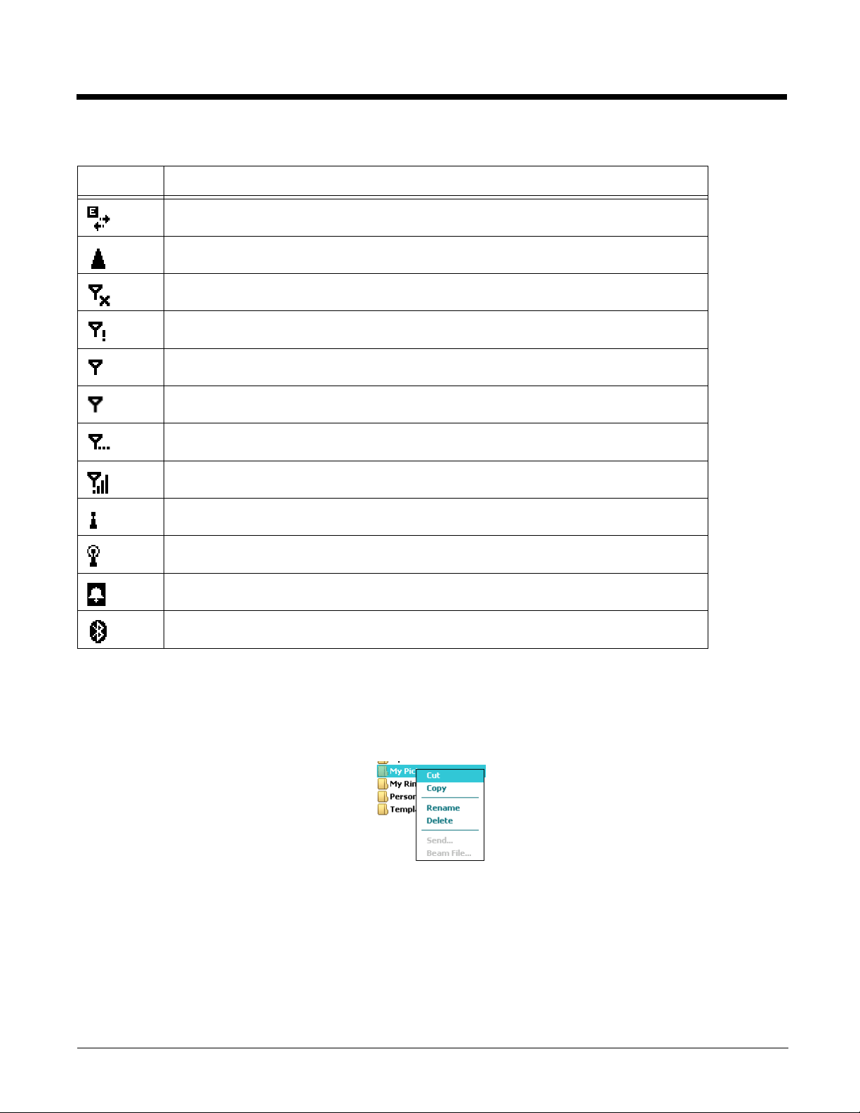
Icons in the Navigation Bar
Indicator Meaning
EDGE connected
Roaming
Radio is disabled
The radio is not connected to a network.
Radio connected
No radio signal
The terminal is searching for a signal.
Radio signal strength
Wi-Fi on
Wi-Fi data call
Pending alarm
Bluetooth
Pop-Up Menus
With pop-up menus, you can quickly choose an action for a selected item. To access a pop-up menu, tap
and hold the stylus on the item name of the action you want to perform. When the menu appears, lift the
stylus, and tap the action you want to perform.
Tap anywhere outside the menu to close the menu without performing an action.
Selecting Programs
To see additional programs loaded on your terminal, tap Start > Programs. The Programs screen displays
the programs that are not listed on the Start menu. To open a program, tap once on the icon.
Note: Some programs have abbreviated labels underneath the icon. To see the full spelling of an abbreviated label, tap and hold
the stylus on the label. Drag the stylus off the label so that the command is not carried out.
2 - 6
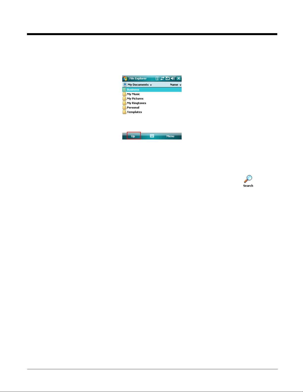
File Explorer
You can also use the File Explorer to find files and organize these files into folders. Tap Start > Programs
> File Explorer.
Tap the Up button at the bottom of the screen to move up one level in the directory.
You can move files in File Explorer by tapping and holding on the item you want to move, and then tapping
Cut or Copy and Paste on popup menus.
Search
The Search feature helps you quickly locate information. Tap Start > Programs > Search .
Enter the text you want to find, select a data type, and then tap Go to start the search. To quickly find
information that is taking up storage space, select Larger than 64 KB in the Type drop-down field.
2 - 7

2 - 8

3
Hardware Overview
Standard Configurations for the 9900
WLAN & WPAN
• Microsoft Windows Mobile 6.1 Classic
• I n t e l X S c a l e P X A 2 7 x 6 2 4 M H z
• 2 5 6 M B R A M X 1 G B F l a s h
• Three in-mold, hard-top keyboard options
• 2500mAh extended life main battery
• Adaptus Imaging Technology: 5100SR/SF
or 5300SR/SF image engines
• 802.11b/g and Bluetooth
WLAN, WPAN, & WWAN with GPS
• Microsoft Windows Mobile 6.1 Professional
• I n t e l X S c a l e P X A 2 7 x 6 2 4 M H z
• 2 5 6 M B R A M X 1 G B F l a s h
• Three in-mold, hard-top keyboard options
• 2500mAh extended life main battery
• Adaptus Imaging Technology: 5100SR/SF
or 5300SR/SF image engines
• 802.11b/g, Bluetooth, and GSM/GPRS
• G P S
Some configurations of the 9900 terminal are available with an external housing made of plastic that is
specifically designed for the healthcare industry. For more information, see Healthcare Housing on page
3-14.
WLAN, WPAN, & WWAN
• Microsoft Windows Mobile 6.1 Professional
• I n t e l X S c a l e P X A 2 7 x 6 2 4 M H z
• 2 5 6 M B R A M X 1 G B F l a s h
• Three in-mold, hard-top keyboard options
• 2500mAh extended life main battery
• Adaptus Imaging Technology: 5100SR/SF
or 5300SR/SF image engines
• 802.11b/g, Bluetooth, and GSM/GPRS
Standard Configuration for the 9950
• Microsoft Windows Mobile 6.1 Classic
• I n t e l X S c a l e P X A 2 7 x 6 2 4 M H z
• 2 5 6 M B R A M X 1 G B F l a s h
• Three in-mold, hard-top keyboard options
• 2500mAh extended life main battery
• Adaptus Imaging Technology: 5100SR/SF or 5300SR/SF image engines
• 802.11b/g and Bluetooth
Standard Configuration for the 9951
• Microsoft Windows Mobile 6.1 Classic
• I n t e l X S c a l e P X A 2 7 x 6 2 4 M H z
• 2 5 6 M B R A M X 1 G B F l a s h
• Three in-mold, hard-top keyboard options
• 2500mAh extended life main battery
• Laser scan engines - HP, LR, and ALR
• 802.11b/g and Bluetooth
3 - 1

Peripherals for the 9900, 9950, and 9951
Each of the following items is sold separately to enhance the capabilities of your Dolphin terminal.
Dolphin HomeBase™ Device
The Dolphin HomeBase device is a charging and communication cradle supporting both RS-232 and USB
communications, which enables it to interface with the majority of PC-based enterprise systems. This
device also contains an auxiliary battery well that charges a spare Li-ion battery.
For more information, see Dolphin HomeBase Device on page 11-1.
Dolphin Mobile Base™ Device
The Dolphin Mobile Base device is a charging and communication cradle designed specifically for inpremise and in-transit data collection applications. It features a flexible mounting bracket, a cigarette
lighter adapter or power cable to adapt it to your environment.
The serial connector supports RS-232 communication and power out to peripheral devices, such as
handheld scanners.
For more information, see Dolphin Mobile Base Device on page 12-1.
Dolphin ChargeBase
The Dolphin ChargeBase is a 4-slot charging cradle that holds, powers, and charges terminals.
For more information, see Dolphin ChargeBase Device on page 13-1.
Dolphin Net Base
The Dolphin Net Base is a 4-slot charging/communication cradle that holds, powers, charges, and
communicates with terminals. Ethernet communication occurs via statically and dynamically-assigned IP
addresses.
For more information about the Dolphin Net Base, please consult the Dolphin Net Base Quick Start Guide.
Dolphin QuadCharger™ Device
The Dolphin QuadCharger device is a 4-slot charging station for 9900, 9950, and 9951 Li-ion battery
packs. The 4th slot features a battery analyzer that completely resets and re-calibrates a battery and
displays its resulting capacity.
For more information, see Dolphin QuadCharger Device on page 14-1.
3 - 2

Accessories for the 9900, 9950, and 9951
Each of the following items is sold separately to enhance your terminal’s capabilities.
Note: When using accessories where the terminal is worn on the body, the terminal’s touch panel must face away
from the body.
Dolphin Mobile Charger
The Dolphin Mobile Charger is a charging cable that connects the terminal directly to a 12 Volt DC power
source, such as a cigarette lighter port inside a vehicle, eliminating the need for a cradle. Intelligent battery
technology on-board the terminal ensures proper charging. The Dolphin Mobile Charger is an ideal lowcost charging solution for in-transit mobile applications.
Dolphin Mobile Mount
The Dolphin Mobile Mount, which holds a Dolphin terminal securely in place inside a vehicle, is an ideal,
low-cost alternative to the Dolphin Mobile Base when communications are not required. When used in
conjunction with the Dolphin Mobile Charger, the Dolphin Mobile Mount creates a complete mounting and
charging solution for in-transit applications. The entire kit includes an adjustable vehicle mounting
bracket.
Communication/Charging Cables
Dolphin communication/charging cable kits are an all-in-one solution for mobile applications. Each cable
kit powers the terminal, charges its main battery, and communicates with host or peripheral devices
without the need for a cradle. Cable kits can support RS-232 or USB communications and are available
with U.K. or European power cords.
Protective Holster
Holsters provide convenient storage for terminals and protect them from damage in mobile environments.
Both holsters feature a front pocket that holds an extra battery, a side pocket to hold an extra stylus, and
a belt loop to secure the holster to a belt.
Protective Enclosure
Protective enclosures help seal and protect terminals from damage while providing full access to all
terminal parts and features. These enclosures feature a swivel clip on the back that enables you to secure
the enclosure to a belt. Enclosures also come with an adjustable shoulder strap for added convenience.
Stylus Kits
There are two stylus kits: one contains three styli and the other includes additional coiled tethers to secure
the stylus to the terminal, which helps prevent loss.
Li-ion Battery Pack
The 7.4v, 18.5 watt hour Li-ion rechargeable battery pack provides the main power for the terminal.
3 - 3
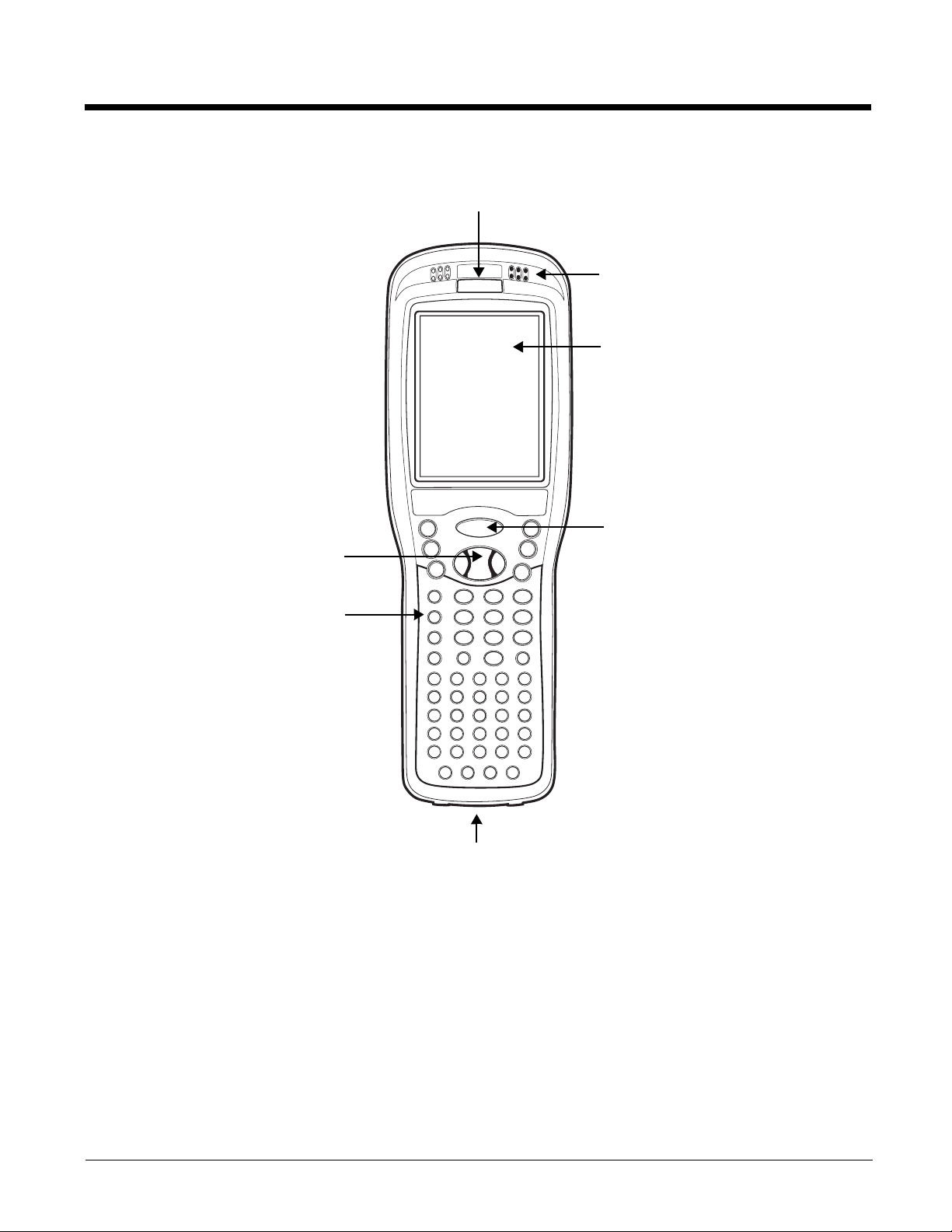
Front Panel: 9900, 9950, and 9951
Indicator LED
Touch Panel Display
Navigation Keys
SCAN Key
Recessed
Keyboard
Front Speaker
I/O Connector
3 - 4

Front Panel Features for the 9900, 9950, and 9951
Front Speaker
The integrated speaker that sounds audio signals as you scan bar code labels and enter data.
The operating frequency range is 500Hz at 71 dB up to 80 dB.
I/O Connector
See I/O Connector on page 3-12.
Indicator LED
The light emitting diode (LED) located at the top of the LCD display flashes and illuminates
during resets and scanning/imaging. This LED can be programmed by various software
applications.
Navigation Keys
The centrally-located navigation keys enable you to move and position the cursor through
software programs. The up and down arrows are programmed to perform specific functions
when pressed in combination with the Blue and Red modifier keys.
For more details, see Using the Navigation Keys on page 5-3.
Recessed Keyboard
There are three keyboard options: 35-key numeric/alpha keyboard, 43-key numeric/alpha
keyboard, and 56-key full alpha/numeric keyboard.
For a complete overview of each keyboard, see Using the Keyboards on page 5-1.
SCAN Key
The SCAN key is centrally located for easy access with the right or left hand. When pressed,
the SCAN key activates the scanner/imager. The SCAN key also functions as a system wakeup control for the terminal.
Touch Panel Display
The color 3.5 inch liquid crystal display (LCD) touch panel is covered with an industrial,
protective lens for greater durability. The video graphic array (VGA) resolution is 1/4 (240 X
320 pixel).
The color LCD is 16 bits/pixel and uses thin film transistor (TFT) technology. The touch panel
backlight lights when the screen is touched, but not when the Backlight key is pressed. For
more information, see Backlight on page 6-8.
The touch panel can be activated by the stylus (included with the terminal) or a finger. For more
information, see Using the Touch Panel on page 3-13.
3 - 5
Back Panel: 9900
Battery Well
Image/Scan Engine Window
Stylus Slot
Rear Speaker
Microphone
Fastener for the
Stylus Tether
IrDA Port
Fastener for the
Stylus Tether
For a description of each callout, see Back Panel Features for the 9900, 9950, and 9951 on page 3-9.
3 - 6
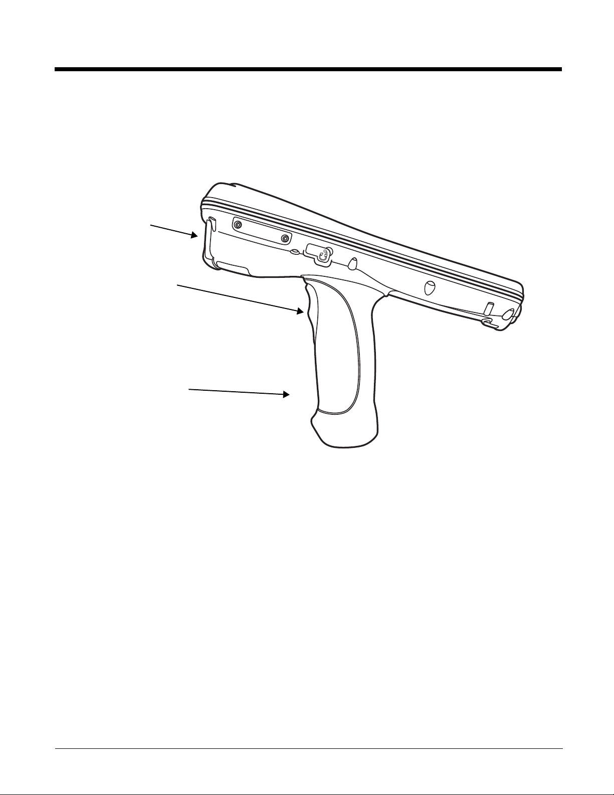
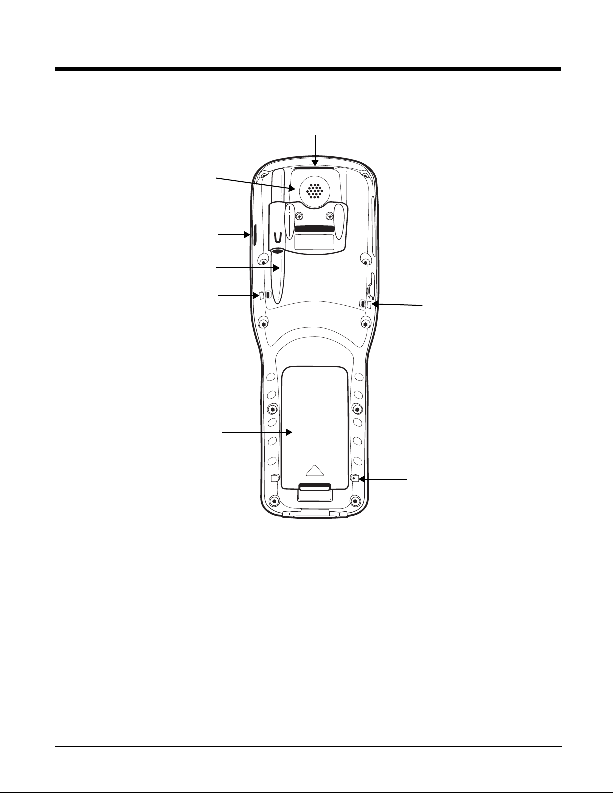
Back and Side Panels: 9950 and 9951
Scan Trigger
Image/Scan Engine
Window
Pistol-Grip
Handle
The back panel of the 9950 and 9951 contains an integrated, pistol-grip handle for a more ergonomic grip
in scan-intensive applications. The stylus is stored inside the handle for easy access.
Side Panel
Scan Trigger
Press the scan trigger to activate the image or scan.
Pistol-Grip Handle
The pistol-grip handle is integrated into the back panel of the terminal and ergonomically
designed to be comfortable through repetitive scans.
3 - 7
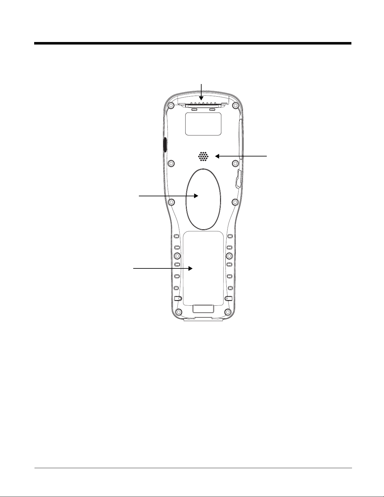
Back Panel
Image/Scan Engine Window
Pistol-Grip Handle
Battery Well
Rear Speaker
For a description of each callout, see Back Panel Features for the 9900, 9950, and 9951 on page 3-9.
3 - 8
Loading...