


 Loading...
DCP200 Profile Controller & Recorder - Product Manual
DCP200 Graphical Profiler Controller
with optional Recorder
51-52-25-150
Issue 1
April 2009
DCP200 Profile Controller & Recorder - Product Manual
This manual supplements the Concise Product manual(s) supplied with each instrument at the time of shipment. Information in this installation, wiring and operation manual is subject to change without notice.
Copyright © Honeywell Inc, April 2009, all rights reserved. No part of this publication may be reproduced, transmitted, transcribed or stored in a retrieval system, or translated into any language in any form by any means without the written permission of Honeywell Inc.
Copies of this manual are available in electronic format on the Honeywell web site www.honeywell.com/ps. Printed versions are available from Honeywell or its representatives.
Note:
It is strongly recommended that applications incorporate a high or low limit protective device, which will shut down the equipment at a preset process condition in order to prevent possible damage to property or products.
WARNING:
THE INTERNATIONAL HAZARD SYMBOL IS INSCRIBED ADJACENT TO THE REAR CONNECTION TERMINALS. IT IS IMPORTANT TO READ THIS MANUAL BEFORE INSTALLING OR COMMISSIONING THE UNIT.
WARNING:
THIS SYMBOL MEANS THE EQUIPMENT IS PROTECTED THROUGHOUT BY DOUBLE INSULATION.
Products covered by this manual are suitable for Indoor use, Installation Category II,
Pollution category 2 environments.
This user guide covers all versions of the Honeywell DCP200 Profile controller & Recorder.
51-52-25-150, Issue 1 – April 2009 |
Page iii |

DCP200 Profile Controller & Recorder - Product Manual
Warranty and Returns Statement
These products are sold by Honeywell Inc under the warranties set forth in the following paragraphs. Such warranties are extended only with respect to a purchase of these products, as new merchandise, directly from Honeywell or from a Honeywell distributor, representative or reseller and are extended only to the first buyer thereof who purchases them other than for the purpose of resale.
Warranty
These products are warranted to be free from functional defects in material and workmanship at the time the products leave the factory and to conform at that time to the specifications set forth in the relevant Honeywell manuals sheet or sheets, for such products for a period of 18 months.
THERE ARE NO EXPRESSED OR IMPLIED WARRANTIES, WHICH EXTEND BEYOND THE WARRANTIES HEREIN AND ABOVE SET FORTH. NO WARRANTY IS MADE OF MERCHANTABILITY OR FITNESS FOR A PARTICULAR PURPOSE WITH RESPECT TO THE PRODUCTS.
Limitations
Honeywell shall not be liable for any incidental damages, consequential damages, special damages, or any other damages, costs or expenses excepting only the cost or expense of repair or replacement as described above. Products must be installed and maintained in accordance with Honeywell’s instructions. There is no warranty against damage to the product resulting from corrosion. Users are responsible for the suitability of the products to their application.
For a valid warranty claim, the product must be returned carriage paid to the supplier within the warranty period. The product must be properly packaged to avoid damage from Electrostatic Discharge or other forms of harm during transit.
Contacts
World Wide Web
The following lists Honeywell's World Wide Web sites that will be of interest to our customers. Honeywell Organization WWW Address (URL)
Corporate http://www.honeywell.com
Honeywell Field Solutions http://www.honeywell.com/ps
Technical tips http://content.honeywell.com/ipc/faq
Telephone
Contact us by telephone at the numbers listed below.
Organization Phone Number
United States and Canada Honeywell 1-800-423-9883
Tech. Support 1-800-525-7439 Service
51-52-25-150, Issue 1 – April 2009 |
Page iv |

DCP200 Profile Controller & Recorder - Product Manual
How to use this manual
This manual is structured to give easy access to the information required for all aspects of the installation and use and of the Graphical Controller. The main sections are shown here, followed by a full table of contents.
Section 1: Introduction - A brief description of the product and it’s features.
Section 2: Installation - Unpacking, installing and panel mounting instructions.
Section 3: Field Upgrade Options - Installation of the plug-in option modules.
Section 4: Wiring Instructions - Guidance on good wiring practice, noise avoidance, wiring diagrams and input/output connections.
Section 5: Powering Up - Powering up procedure and descriptions of displays & switches.
Section 6: Messages & Error Indications - Display Messages and fault indications.
Section 7: Configuration & Use - Describes operating and configuration modes available.
These include Operation Mode; the Main and Configuration menus; the Easy Setup Wizard;
Supervisor Mode; Automatic tuning; Product and Service Information. Also available on some models are menus to setup the USB, Data Recorder and Profiler features.
Section 8: The USB Interface Option – Describes uploading or downloading of instrument settings, profiles or recorder logs to a USB memory stick.
Section 9: The Data Recorder Option – Describes the Data recorder feature. This allows process data to be stored in to memory for later download and analysis.
Section 10: Profiler – Describes the Profiler feature. A profile controls the value of the setpoint over time; increasing, decreasing or holding its value as required.
Section 11: Manually Tuning - Advice on manually adjusting the controller to the process characteristics.
Sections 12: Serial Communications - Details the physical layer and message formats used for the RS485 and Ethernet communications options.
Sections 13: Modbus Parameters - Details the parameter addresses and data formats used for the Modbus RTU and TCP communications protocols.
Section 14: Calibration - Step-by-step instructions to calibrate the instrument. This section is intended for use by suitably qualified personnel.
Appendix 1: Glossary - Explanations of the terms used and product features.
Appendix 2: PC Software – Using the software suite.
Appendix 3: Specifications - Technical specifications for all products in the range.
Appendix 4: Product Coding - Product model/ordering codes.
51-52-25-150, Issue 1 – April 2009 |
Page 5 |

Contents
DCP200 Profile Controller & Recorder - Product Manual
Page Number:
Warranty and Returns Statement .................................................................................................... |
iv |
|
1 |
Introduction .......................................................................................................................... |
14 |
2 |
Installation ............................................................................................................................ |
15 |
|
Unpacking ........................................................................................................................................... |
15 |
|
Installation ........................................................................................................................................... |
15 |
|
Panel-Mounting ................................................................................................................................... |
15 |
|
Cleaning.............................................................................................................................................. |
16 |
3 |
Field Upgrade Options......................................................................................................... |
17 |
|
Options Modules and Functions........................................................................................................... |
17 |
|
Preparing to Install or Remove Options Modules.................................................................................. |
18 |
|
Removing/Replacing Option Modules .................................................................................................. |
19 |
|
Replacing the Instrument in its Housing ............................................................................................... |
20 |
|
Auto Detection of Option Modules........................................................................................................ |
20 |
|
Replacement of Power Supply or Input Boards .................................................................................... |
20 |
|
Data Recorder Board........................................................................................................................... |
21 |
4 |
Electrical Installation ........................................................................................................... |
22 |
|
Installation Considerations ................................................................................................................... |
22 |
|
AC Power Wiring - Neutral (for 100 to 240V AC versions) .................................................................... |
22 |
|
Wire Isolation....................................................................................................................................... |
22 |
|
Use of Shielded Cable ......................................................................................................................... |
23 |
|
Noise Suppression at Source............................................................................................................... |
23 |
|
Sensor Placement (Thermocouple or RTD).......................................................................................... |
24 |
|
Thermocouple Wire Identification Chart ............................................................................................... |
24 |
|
Connections and Wiring....................................................................................................................... |
25 |
|
Power Connections ........................................................................................................................ |
26 |
|
Universal Input Connections ........................................................................................................... |
27 |
|
Option Slot 1 Connections .............................................................................................................. |
29 |
|
Option Slot 2 Connections .............................................................................................................. |
30 |
|
Option Slot 3 Connections .............................................................................................................. |
32 |
|
Option Slot A Connections.............................................................................................................. |
35 |
|
Option Slot B Connections.............................................................................................................. |
36 |
5 |
Powering Up ......................................................................................................................... |
37 |
|
Powering Up Procedure....................................................................................................................... |
37 |
|
Front Panel Overview .......................................................................................................................... |
37 |
|
Display ................................................................................................................................................ |
37 |
|
LED Functions..................................................................................................................................... |
38 |
|
Keypad................................................................................................................................................ |
38 |
6 |
Messages and Error Indications ......................................................................................... |
39 |
|
Start-up Errors..................................................................................................................................... |
39 |
Page 6 |
Table Of Contents |
51-52-25-150, Issue 1 – April 2009 |

|
DCP200 Profile Controller & Recorder - Product Manual |
|
|
Input Problems .................................................................................................................................... |
39 |
|
USB Data Transfer Problems............................................................................................................... |
40 |
|
Getting Help ........................................................................................................................................ |
40 |
7 |
Configuration and Use ......................................................................................................... |
41 |
|
Operation Mode................................................................................................................................... |
41 |
|
Base, Trend & Profile Operating Screens....................................................................................... |
41 |
|
Adjusting the Local Setpoint(s) ...................................................................................................... |
43 |
|
Adjusting the Setpoint Ramp Rate ................................................................................................. |
44 |
|
Selecting Automatic or Manual Mode............................................................................................. |
44 |
|
Control Enable or Disable .............................................................................................................. |
44 |
|
Main Menu........................................................................................................................................... |
45 |
|
Entry into the Main Menu............................................................................................................... |
45 |
|
Unlock Codes................................................................................................................................ |
45 |
|
Setup Wizard....................................................................................................................................... |
46 |
|
Manual entry to the Setup Wizard .................................................................................................. |
46 |
|
Supervisor Mode ................................................................................................................................. |
47 |
|
Entry into Supervisor Mode............................................................................................................ |
47 |
|
Configuration Menu ............................................................................................................................. |
48 |
|
Entry into the Configuration Menu.................................................................................................. |
48 |
|
Input Configuration Sub-Menu ............................................................................................................. |
49 |
|
Control Configuration Sub-Menu.......................................................................................................... |
50 |
|
Output Configuration Sub-Menu........................................................................................................... |
52 |
|
Alarm Configuration Sub-Menu ............................................................................................................ |
53 |
|
Communications Configuration Sub-Menu ........................................................................................... |
53 |
|
Recorder Configuration Sub-Menu....................................................................................................... |
54 |
|
Clock Configuration Sub-Menu ............................................................................................................ |
55 |
|
Display Configuration Sub-Menu.......................................................................................................... |
55 |
|
Lock Code View................................................................................................................................... |
56 |
|
Lost Lock Codes............................................................................................................................ |
56 |
|
Resetting To Defaults .......................................................................................................................... |
57 |
|
Automatic Tuning Menu ....................................................................................................................... |
57 |
|
Profiler Setup Menu ............................................................................................................................. |
58 |
|
Profiler Control Menu........................................................................................................................... |
61 |
|
USB Menu........................................................................................................................................... |
62 |
|
Recorder Menu.................................................................................................................................... |
63 |
|
Product Information Mode.................................................................................................................... |
63 |
|
Service Information Mode .................................................................................................................... |
64 |
8 |
The USB Interface................................................................................................................. |
65 |
|
Using the USB Port.............................................................................................................................. |
65 |
|
USB Memory Stick Folders & Files ................................................................................................ |
65 |
9 |
The Data Recorder Option ................................................................................................... |
66 |
51-52-25-150, Issue 1 – April 2009 |
Table Of Contents |
Page 7 |

|
DCP200 Profile Controller & Recorder - Product Manual |
|
|
Introduction ......................................................................................................................................... |
66 |
|
Changes To Operation Mode............................................................................................................... |
66 |
10 |
The Profiler Option............................................................................................................... |
67 |
|
Profile Components ............................................................................................................................. |
67 |
|
Profile Starting & Standard Segments.................................................................................................. |
68 |
|
Loops Segments.................................................................................................................................. |
69 |
|
Profile Running / Holding vs. Hold Segments ....................................................................................... |
69 |
|
The Auto-Hold Feature ........................................................................................................................ |
70 |
|
Profile Cycles & Repeat Sequences..................................................................................................... |
71 |
|
Power/Signal Lost Recovery Actions.................................................................................................... |
71 |
|
Profile End Actions .............................................................................................................................. |
72 |
|
Profile Abort Actions ............................................................................................................................ |
73 |
11 |
Manually Tuning Controllers ............................................................................................... |
74 |
|
Single Control Tuning (PID with Primary Output only) .......................................................................... |
74 |
|
Dual Control Tuning (PID with Primary and Secondary Outputs) .......................................................... |
75 |
|
PI Tuning (Valve, Damper & Speed Controllers) .................................................................................. |
75 |
|
Fine Tuning. ........................................................................................................................................ |
77 |
12 |
Serial Communications........................................................................................................ |
78 |
|
Supported Protocols ............................................................................................................................ |
78 |
|
RS485 Configuration ........................................................................................................................... |
78 |
|
Ethernet Configuration......................................................................................................................... |
78 |
|
Supported Modbus Functions .............................................................................................................. |
80 |
|
Function Descriptions .......................................................................................................................... |
80 |
|
Exception Responses ..................................................................................................................... |
82 |
13 |
Modbus Parameters............................................................................................................. |
83 |
|
Example Register Address Calculations ......................................................................................... |
83 |
|
Universal Process Input Parameters .................................................................................................... |
84 |
|
Option Slot A Parameters .................................................................................................................... |
86 |
|
Option Slot B Parameters .................................................................................................................... |
87 |
|
Option Slot 1 Parameters..................................................................................................................... |
88 |
|
Option Slot 2 Parameters..................................................................................................................... |
90 |
|
Option Slot 3 Parameters..................................................................................................................... |
93 |
|
Option Slot 4 Parameters..................................................................................................................... |
96 |
|
Setpoint Parameters.......................................................................................................................... |
101 |
|
Control Parameters............................................................................................................................ |
102 |
|
Alarm parameters .............................................................................................................................. |
104 |
|
Recorder & Clock Parameters............................................................................................................ |
106 |
|
Display Parameters ........................................................................................................................... |
109 |
|
Profiler Control & Status Parameters ................................................................................................. |
112 |
|
Profile Setup Via Modbus .................................................................................................................. |
114 |
|
Instrument Data................................................................................................................................. |
129 |
Page 8 |
Table Of Contents |
51-52-25-150, Issue 1 – April 2009 |

|
DCP200 Profile Controller & Recorder - Product Manual |
|
14 |
Calibration........................................................................................................................... |
130 |
|
Calibration Reminder ......................................................................................................................... |
130 |
|
Equipment Required For Checking or Calibrating The Universal Input................................................ |
130 |
|
Calibration Check .............................................................................................................................. |
130 |
|
Recalibration Procedure .................................................................................................................... |
131 |
15 |
Appendix 1 – Glossary of Terms Used.............................................................................. |
132 |
|
Active Setpoint................................................................................................................................... |
132 |
|
Actual Setpoint .................................................................................................................................. |
132 |
|
Alarm Configuration ........................................................................................................................... |
132 |
|
Alarm Operation ................................................................................................................................ |
134 |
|
Alarm Inhibit ...................................................................................................................................... |
135 |
|
Alarm Types ...................................................................................................................................... |
135 |
|
Alternative Setpoint............................................................................................................................ |
135 |
|
Auto Pre-Tune ................................................................................................................................... |
135 |
|
Automatic Reset ................................................................................................................................ |
135 |
|
Auxiliary Input.................................................................................................................................... |
136 |
|
Auxiliary Input Lower Limit ................................................................................................................. |
136 |
|
Auxiliary Input Offset.......................................................................................................................... |
136 |
|
Auxiliary Input Type ........................................................................................................................... |
136 |
|
Auxiliary Input Upper Limit ................................................................................................................. |
136 |
|
Band Alarm Value.............................................................................................................................. |
136 |
|
Bar Graphs........................................................................................................................................ |
137 |
|
Bias (Manual Reset) .......................................................................................................................... |
137 |
|
Bumpless Transfer............................................................................................................................. |
137 |
|
Cascade Control ................................................................................................................................ |
137 |
|
Clock Configuration ........................................................................................................................... |
138 |
|
Communications Write Enable ........................................................................................................... |
138 |
|
Configuration Menu ........................................................................................................................... |
138 |
|
Contactor........................................................................................................................................... |
138 |
|
Control Configuration......................................................................................................................... |
138 |
|
Control Deviation ............................................................................................................................... |
139 |
|
Control Action.................................................................................................................................... |
139 |
|
Control Enable/Disable ...................................................................................................................... |
139 |
|
Control Type...................................................................................................................................... |
139 |
|
Controller........................................................................................................................................... |
139 |
|
Controller Mode ................................................................................................................................. |
139 |
|
Correcting Variable ............................................................................................................................ |
139 |
|
CPU .................................................................................................................................................. |
140 |
|
Current Proportioning Control ............................................................................................................ |
140 |
|
Custom Display Mode........................................................................................................................ |
140 |
|
Cycle Time ........................................................................................................................................ |
140 |
51-52-25-150, Issue 1 – April 2009 |
Table Of Contents |
Page 9 |

DCP200 Profile Controller & Recorder - Product Manual
Data Recorder ................................................................................................................................... |
140 |
Deadband.......................................................................................................................................... |
140 |
Derivative Action................................................................................................................................ |
140 |
Deviation Alarm Value ....................................................................................................................... |
141 |
Digital Input ....................................................................................................................................... |
141 |
Direct Acting Control.......................................................................................................................... |
141 |
Display Configuration......................................................................................................................... |
141 |
Display Languages ............................................................................................................................ |
141 |
Display Resolution............................................................................................................................. |
142 |
Effective Setpoint............................................................................................................................... |
142 |
Engineering Units .............................................................................................................................. |
142 |
Ethernet............................................................................................................................................. |
142 |
Indicator ............................................................................................................................................ |
142 |
Input Configuration ............................................................................................................................ |
142 |
Input Filter Time Constant.................................................................................................................. |
142 |
Input Range....................................................................................................................................... |
143 |
Input Span......................................................................................................................................... |
143 |
Integral Time Constant....................................................................................................................... |
143 |
Latching Relay................................................................................................................................... |
143 |
LED................................................................................................................................................... |
143 |
Linear Input ....................................................................................................................................... |
143 |
Linear Output..................................................................................................................................... |
144 |
Limit Controller .................................................................................................................................. |
144 |
Local Setpoints.................................................................................................................................. |
144 |
Lock Codes ....................................................................................................................................... |
144 |
Logical Combination of Alarms........................................................................................................... |
144 |
Loop Alarm ........................................................................................................................................ |
145 |
LSD................................................................................................................................................... |
145 |
mADC ............................................................................................................................................... |
145 |
Main Menu ........................................................................................................................................ |
146 |
Manual Loop Alarm Time................................................................................................................... |
146 |
Manual Mode..................................................................................................................................... |
146 |
Master & Slave Controllers ................................................................................................................ |
146 |
Minimum Duration Of Change............................................................................................................ |
147 |
Modbus RTU ..................................................................................................................................... |
147 |
Modbus TCP ..................................................................................................................................... |
147 |
Modulating Valve............................................................................................................................... |
148 |
Multi-Point Scaling............................................................................................................................. |
148 |
mVDC ............................................................................................................................................... |
148 |
On-Off Control ................................................................................................................................... |
148 |
On-Off Differential (On-Off Hysteresis)............................................................................................... |
148 |
Page 10 |
Table Of Contents |
51-52-25-150, Issue 1 – April 2009 |
DCP200 Profile Controller & Recorder - Product Manual
Operation Mode................................................................................................................................. |
149 |
Output Configuration.......................................................................................................................... |
149 |
Overlap/Deadband............................................................................................................................. |
149 |
PD Control......................................................................................................................................... |
151 |
PI Control .......................................................................................................................................... |
151 |
PID Control........................................................................................................................................ |
151 |
PLC ................................................................................................................................................... |
151 |
Pre-Tune ........................................................................................................................................... |
151 |
Power Output Limits .......................................................................................................................... |
152 |
Primary Proportional Band ................................................................................................................. |
153 |
Process High Alarm n Value .............................................................................................................. |
153 |
Process Input .................................................................................................................................... |
153 |
Process Low Alarm n Value ............................................................................................................... |
153 |
Process Variable (PV)........................................................................................................................ |
153 |
Process Variable Offset ..................................................................................................................... |
154 |
Profile Control Menu .......................................................................................................................... |
154 |
Profile Events .................................................................................................................................... |
154 |
Profile Header.................................................................................................................................... |
154 |
Profile Segments ............................................................................................................................... |
154 |
Profile Setup Menu ............................................................................................................................ |
154 |
Profiler............................................................................................................................................... |
155 |
Profiler Mode ..................................................................................................................................... |
155 |
Proportional Control........................................................................................................................... |
155 |
Rate .................................................................................................................................................. |
155 |
Rate Of Change Alarm....................................................................................................................... |
155 |
Recorder Configuration...................................................................................................................... |
155 |
Recorder Option ................................................................................................................................ |
156 |
Recorder Menu.................................................................................................................................. |
156 |
Relay................................................................................................................................................. |
156 |
Remote Setpoint (RSP) ..................................................................................................................... |
156 |
Retransmit Output.............................................................................................................................. |
156 |
Retransmit Output n Scale Maximum ................................................................................................. |
156 |
Retransmit Output n Scale Minimum .................................................................................................. |
157 |
Reset To Defaults.............................................................................................................................. |
157 |
Reverse Acting Control ...................................................................................................................... |
157 |
RS485 ............................................................................................................................................... |
157 |
RTD................................................................................................................................................... |
158 |
Scale Range Upper Limit ................................................................................................................... |
158 |
Scale Range Lower Limit ................................................................................................................... |
158 |
Secondary Proportional Band ............................................................................................................ |
158 |
Self-Tune........................................................................................................................................... |
159 |
51-52-25-150, Issue 1 – April 2009 |
Table Of Contents |
Page 11 |

|
DCP200 Profile Controller & Recorder - Product Manual |
|
|
Sensor Break Pre-Set Power ............................................................................................................. |
159 |
|
Serial Communications Configuration ................................................................................................ |
160 |
|
Serial Communications Option........................................................................................................... |
160 |
|
Setpoint............................................................................................................................................. |
160 |
|
Setpoint Upper Limit .......................................................................................................................... |
160 |
|
Setpoint Lower Limit .......................................................................................................................... |
160 |
|
Setpoint Ramp Editing ....................................................................................................................... |
160 |
|
Setpoint Ramp Rate .......................................................................................................................... |
161 |
|
Setpoint Selection.............................................................................................................................. |
161 |
|
Setup Wizard..................................................................................................................................... |
161 |
|
Solid State Relay (SSR)..................................................................................................................... |
161 |
|
Solenoid Valve .................................................................................................................................. |
162 |
|
Supervisor Mode ............................................................................................................................... |
162 |
|
Thermocouple ................................................................................................................................... |
162 |
|
Three Point Stepping Control............................................................................................................. |
162 |
|
Time Proportioning Control ................................................................................................................ |
163 |
|
Trend Display .................................................................................................................................... |
163 |
|
Tuning ............................................................................................................................................... |
163 |
|
Tuning Menu ..................................................................................................................................... |
163 |
|
Triac.................................................................................................................................................. |
164 |
|
USB Menu......................................................................................................................................... |
164 |
|
Valve Motor Drive Control (VMD)....................................................................................................... |
164 |
|
VDC .................................................................................................................................................. |
164 |
|
VMD.................................................................................................................................................. |
164 |
16 |
PC SOFTWARE................................................................................................................... |
165 |
|
Using The Software ........................................................................................................................... |
165 |
|
Instrument Configuration.................................................................................................................... |
166 |
|
Profile Creation And Editing ............................................................................................................... |
167 |
|
Changing the Start-up Splash Screen ................................................................................................ |
169 |
|
Changing the Alternate Display Language ......................................................................................... |
169 |
|
Instrument Simulation ........................................................................................................................ |
169 |
|
Configuring The Connection .............................................................................................................. |
169 |
|
Network Configuration For Modbus TCP Options............................................................................... |
171 |
17 |
Appendix 2 - Specifications............................................................................................... |
173 |
|
Universal Process Input ..................................................................................................................... |
173 |
|
General Input Specifications ......................................................................................................... |
173 |
|
Thermocouple Input...................................................................................................................... |
173 |
|
Resistance Temperature Detector (RTD) Input ............................................................................. |
174 |
|
DC Linear Input ............................................................................................................................ |
175 |
|
Auxiliary Inputs .................................................................................................................................. |
175 |
|
Digital Inputs...................................................................................................................................... |
176 |
Page 12 |
Table Of Contents |
51-52-25-150, Issue 1 – April 2009 |

|
|
DCP200 Profile Controller & Recorder - Product Manual |
|
Output Specifications......................................................................................................................... |
177 |
|
Communications................................................................................................................................ |
179 |
|
Display .............................................................................................................................................. |
180 |
|
Control Loop...................................................................................................................................... |
180 |
|
Data Recorder Option........................................................................................................................ |
180 |
|
Profiler Option.................................................................................................................................... |
181 |
|
Alarms............................................................................................................................................... |
181 |
|
Conditions For Use ............................................................................................................................ |
182 |
|
Standards.......................................................................................................................................... |
182 |
|
Dimensions........................................................................................................................................ |
182 |
18 |
Appendix 3 - Product Coding............................................................................................. |
183 |
51-52-25-150, Issue 1 – April 2009 |
Table Of Contents |
Page 13 |

DCP200 Profile Controller & Recorder - Product Manual
1 Introduction
This product is a 1/4 DIN size (96 x 96mm front) microprocessor based graphical process controller, featuring a 160 x 80 pixel, monochrome LCD with a dual colour (red/green) backlight. It can control process variables from a variety of sources such as temperature, pressure, flow and level.
The operating voltage is either 100-240V at 50/60 Hz or 24V-48V AC/DC depending on the model purchased. Optional features include a USB interface, RS485 or Ethernet communications, profile controlling and data recording. Non-volatile memory protects against data or configuration loss during power outages. If the unit is left un-powered, a lithium battery powers the data recorder’s real-time clock for a minimum of one year.
The USB Interface option allows uploading or downloading instrument configuration settings to/from a USB memory stick, for easy configuration of multiple instruments or transfer to/from the PC configuration software. If the Data Recorder of Profiler options are fitted, recordings and profile information can also be transferred via the memory stick.
The Data Recorder option allows the user to make recordings of the process over time. Recordings can be transferred to a memory stick using the USB Port or downloaded using one of the communications options.
The Profiler option allows the user to predefine up 255 segments, shared amongst up to 64
Setpoint Profiles. These control the setpoint level over time, increasing, decreasing or holding its value as required. When combined with the real-time clock of the Data Recorder option, the profiling capabilities are expanded to allow automatic program start at a defined time and day.
Inputs are user configurable for thermocouple and RTD probes, as well as linear process signal types such as mVDC, VDC or mADC. Multipoint scaling can compensate for nonlinear signals. Output options include relays, SSR drivers, triacs or linear mV/voltage modules. These can be used for process control, alarms or retransmission of the process variable or setpoint to external devices. Transmitter Power Supply options can provide an unregulated 24V DC (22mA) auxiliary output voltage, or a 0 to 10VDC stabilised excitation for external signal transmitters.
Alarm indication is standard on all instruments; up to five alarms can be defined. Alarms may be set as process high or low, deviation (active above or below controller setpoint), band (active both above and below setpoint), rate of input change, control loop or signal break types. Alarm status can be indicated by lighting an LED, changing the display backlight colour or viewing the alarm status screen. These alarms can be linked to any suitable output.
The controller can be programmed for on-off, time proportioning, or current proportioning control implementations, depending on the output modules fitted, and feature manual or automatic tuning of the PID parameters. A secondary control output is available when additional output modules are fitted. Optional analogue Remote Setpoint inputs can be included. Configuration of the major settings is made easy by a Setup Wizard that runs automatically at first ever power-up or whenever option modules have been changed. Access to the full range of parameters is via a simple menu driven front panel interface, or the PC based configuration software.
Page 14 |
Introduction |
51-52-25-150, Issue 1 – April 2009 |

DCP200 Profile Controller & Recorder - Product Manual
2 Installation
Unpacking
1.Remove the product from its packing. Retain the packing for future use, in case it is necessary to transport the instrument to a different site or to return it to the supplier for repair/testing.
2.The instrument is supplied with a panel gasket and push-fit fixing strap. Concise manual(s) are supplied with the instrument, in one or more languages. Examine the delivered items for damage or defects. If any are found, contact your supplier immediately.
Installation
CAUTION:
Installation should only be performed by technically competent personnel. It is the responsibility of the installing engineer to ensure that the configuration is safe. Local Regulations regarding electrical installation & safety must be observed (e.g. US National Electrical Code (NEC) or Canadian Electrical Code).
Figure 1. Main dimensions
Panel-Mounting
The mounting panel must be rigid and may be up to 6.0mm (0.25 inches) thick. The cut-out size is:
92mm x 92mm (+0.5mm / -0.0mm).
51-52-25-150, Issue 1 – April 2009 |
Installation |
Page 15 |

DCP200 Profile Controller & Recorder - Product Manual
Instruments may be mounted side-by-side in a multiple installation, but instrument to panel moisture and dust sealing will be compromised. Allow a 20mm gap above, below and behind the instrument for ventilation. The cut-out width (for n instruments) is:
(96n - 4) mm or (3.78n - 0.16) inches
If panel sealing must be maintained, mount each instrument into an individual cut-out with
6mm or more clearance between the edges of the holes.
Note:
The mounting clamp tongues may engage the ratchets either on the sides or the top/bottom faces of the Instrument housing. When installing several Instruments side-by- side in one cut-out, use the ratchets on the top/bottom faces.
CAUTION:
Ensure the inside of the panel remains within the instrument operating temperature and that there is adequate airflow to prevent overheating.
Gasket
Mounting Panel 
Clamp
Ratchets 
Instrument
Housing
Slide mounting clamp over the instrument housing towards rear face of mounting panel until the tongues engage in ratchets and instrument is clamped in position.
Hold instrument firmly in position (apply pressure to bezel only)
Figure 2. Panel-Mounting the instrument
CAUTION:
Do not remove the panel gasket, as this may result in inadequate clamping and sealing of the instrument to the panel.
Once the instrument is installed in its mounting panel, it may be subsequently removed from it’s housing, if necessary, as described in the Fitting and Removing Option Modules section.
Cleaning
Clean the front panel by washing with warm soapy water and dry immediately If the USB option is fitted, close the USB port cover before cleaning.
Page 16 |
Installation |
51-52-25-150, Issue 1 – April 2009 |

DCP200 Profile Controller & Recorder - Product Manual
3 Field Upgrade Options
Options Modules and Functions
The available plug-in modules, options and accessories are shown in below:
Table 1. Options & Accessories
|
PART |
|
|
|
|
|
BOARD |
|
|
|
|
DESCRIPTION |
|
|
IDENTIFICATION |
|
|
|
NUMBER |
|
|
|
|
|
||
|
|
|
|
|
|
NUMBER |
|
|
|
|
|
|
|
|
|
|
|
|
OPTION SLOT 1 |
|
|
|
|
|
|
|
|
|
|
|
|
|
|
||
51453391-517 |
|
|
Single Relay Output for option slot 1 |
716/01 |
|
|||
51453391-502 |
|
|
Single SSR Driver Output for option slot 1 |
716/02 |
|
|||
51453391-503 |
|
|
Triac Output for option slot 1 |
716/03 |
|
|||
51453391-504 |
|
|
Linear mA / Voltage Output module for option slot 1 |
639/01 |
|
|||
|
OPTION SLOT 2 or 3 |
|
|
|
|
|
|
|
|
|
|
|
|
|
|
||
51453391-518 |
|
|
Single Relay Output for option slot 2 or 3 |
717/01 |
|
|||
51453391-510 |
|
|
Dual Relay Output for option slot 2 or 3 |
644/01 |
|
|||
51453391-507 |
|
|
Single SSR Driver Output for option slot 2 or 3 |
717/02 |
|
|||
51453391-519 |
|
|
Dual SSR Driver Output for option slot 2 or 3 |
644/02 |
|
|||
51453391-508 |
|
|
Triac module Output for slot 2 or 3 |
647/01 |
|
|||
51453391-509 |
|
|
Linear mA / Voltage Output for option slot 2 or 3 |
640/01 |
|
|||
51453391-111 |
|
|
24VDC Transmitter Power Supply for option slot 2 or 3 |
642/01 |
|
|||
|
OPTION SLOT A |
|
|
|
|
|
|
|
|
|
|
|
|
|
|
||
51453391-513 |
|
|
Digital Input for option slot A |
641/02 |
|
|||
51453391-515 |
|
|
Basic Auxiliary Input for option slot A |
653/01 |
|
|||
51453391-512 |
|
|
RS485 Serial Communications for option slot A |
680/01 |
|
|||
51453391-521 |
|
|
Ethernet Communications for option slot A |
707/01 |
|
|||
|
OPTION SLOT B |
|
|
|
|
|
|
|
|
|
|
|
|
|
|
||
51453391-516 |
|
|
Full Auxiliary Input (inc digital input B) for option slot B |
641/01 |
|
|||
|
OPTION SLOT 4 |
|
|
|
|
|
|
|
|
|
|
|
|
|
|
||
51453391-520 |
|
|
4-Relay Output for option slot 4 |
703/01 |
|
|||
|
ACCESSORIES |
|
|
|
|
|
|
|
|
|
|
|
|
|
|
|
|
51453391-522 |
|
|
Blue Control PC Configuration Software & Lead |
|
|
|
||
Note:
Modules can be either pre-installed at the time of manufacture, or retrofitted in the field.
CAUTION:
Plastic pegs prevent fitting of older non-reinforced single relay modules (Board Identification Numbers 637/01 and 638/01). Fitting the older relay modules reduces the isolation rating to Basic 240V Isolation and is therefore not recommended. Remove this peg when fitting Dual Relay Modules.
Note:
All dual relay modules have reinforced isolation.
51-52-25-150, Issue 1 – April 2009 |
Electrical Installation |
Page 17 |

DCP200 Profile Controller & Recorder - Product Manual
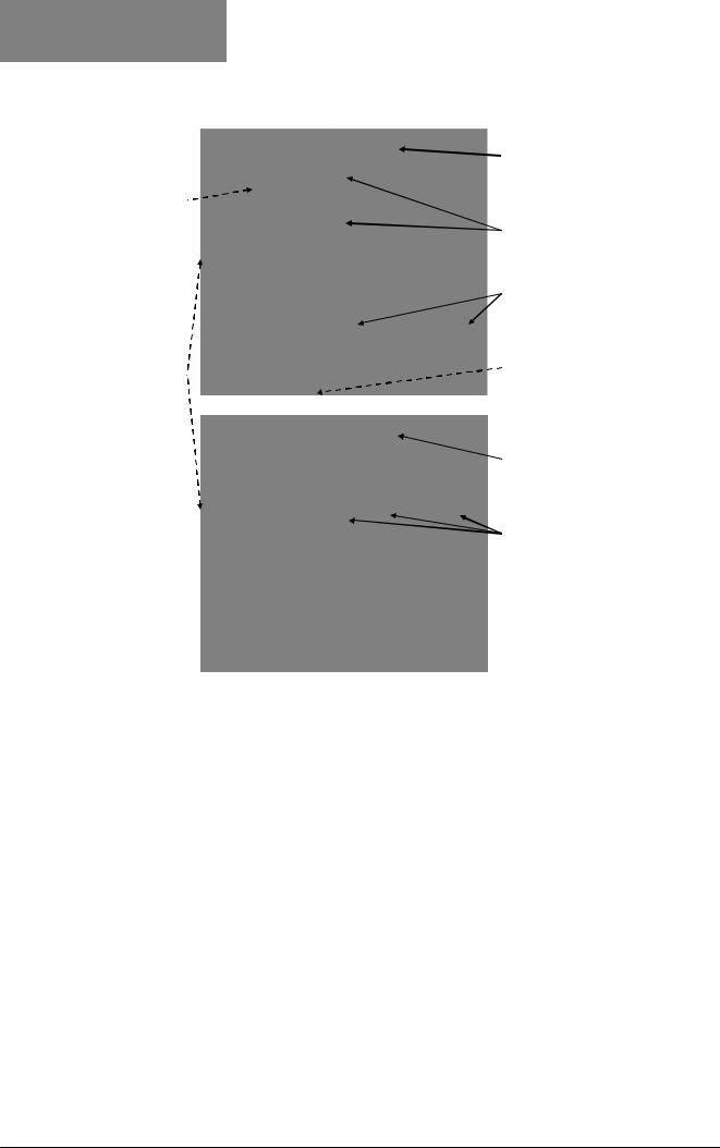
Board Positions
 Board Mounting Struts
 Option 4 Module
 Option A Module
Option 3 Module
Universal Input Board
Power Supply Board
Option B Module
Option 1 Module
(hidden below B)
 Option 2 Module
Option C Module
Figure 3. Rear view (uncased) & board positions
Preparing to Install or Remove Options Modules
CAUTION:
Before removing the instrument from it’s housing, ensure that all power has been removed from the rear terminals. Modules / boards should only be replaced by a trained technician.
1.Remove the instrument from its housing by gripping the edges of the front panel (there is a finger grip on each edge) and pull the instrument forwards. This will release the instrument from the rear connectors in the housing and will give access to the boards.
2.Take note of the orientation of the instrument for subsequent replacement into the housing. The positions of the boards in the instrument are shown above.
Page 18 |
Electrical Installation |
51-52-25-150, Issue 1 – April 2009 |
|
DCP200 Profile Controller & Recorder - Product Manual |
||
|
|
|
|
Main Board Connectors |
|
|
|
|
|
|
|
POWER SUPPLY |
Option 3 Slot |
||
BOARD |
Connector PL4B |
||
Transformer Colour |
|
|
|
Code |
Option Slot A |
||
100-240V (Yellow) |
|||
Connectors PL5, & PL6 |
|||
24-48V(Blue) |
|||
|
|
||
|
Option 1 Slot |
||
|
Connectors PL7 & PL8 |
||
Display Board |
PC Configurator |
||
Connections |
Socket SK1 |
||
|
Option 2 Slot |
||
UNIVERSAL INPUT |
Connector PL4A |
||
|
|
||
BOARD |
Option Slot B |
||
|
|||
|
Connectors PL2A, PL2B & |
||
|
PL2C |
||
Figure 4. Main board connectors
Removing/Replacing Option Modules
1.To remove or replace modules in Option Slots 1, 2, 3, A or B, it is necessary to detach the Power Supply and Input boards from the front panel by lifting first the upper and then lower mounting struts.
2.Remove or fit the modules to the connectors on the Power Supply and Input boards. The location of the connectors is shown below. Plastic pegs prevent fitting of older nonreinforced single relay modules – Remove the peg to fit dual relay modules
3.Assemble the Power Supply and Input boards together. Tongues on each option module locate into a slots cut into the main boards, opposite each of the connectors. Hold the Power and Input boards together and relocate them back on their mounting struts.
4.Remove or replace the Slot C and 4 modules as required.
5.Push the boards forward to ensure correct connection to the front Display/CPU board.
CAUTION:
Check for correct orientation of the modules and that all pins are located correctly.
51-52-25-150, Issue 1 – April 2009 |
Electrical Installation |
Page 19 |

DCP200 Profile Controller & Recorder - Product Manual
Replacing the Instrument in its Housing
CAUTION:
Before replacing the instrument in it’s housing, ensure that all power has been removed from the rear terminals.
With the required option modules correctly located into their respective positions the instrument can be replaced into it’s housing as follows:
1.Hold the Power Supply and Input boards together.
2.Align the boards with the guides in the housing.
3.Slowly and firmly, push the instrument in position.
CAUTION:
Ensure that the instrument is correctly orientated. A mechanical stop will operate if an attempt is made to insert the instrument in the wrong orientation, this stop MUST NOT be over-ridden.
Auto Detection of Option Modules
The instrument automatically detects which option modules have been fitted into each slot. The menus and screens change to reflect the options compatible with the hardware fitted. The modules fitted can be viewed in the products information menu, as detailed in the Product Information Mode section of this manual.
Replacement of Power Supply or Input Boards
It is recommended that users only change these boards if it is unavoidable..
1.Remove the instrument from it’s housing as detailed above.
2.Remove all option modules.
3.Replace the Power Supply or Input board as required. Carefully observe the transformer colour and the case labelling to check the supply voltage when replacing the power supply board.
4.Reassemble the unit in it’s case.
5.If the input board has to be replaced, a full recalibration must be carried out before the instrument is used. Refer to the calibration section of this manual for instructions.
CAUTION:
Replacement of boards must be carried out by a trained technician.
If the Power Supply board does not match the labelling, users may apply incorrect voltage resulting in irreparable damage.
Page 20 |
Electrical Installation |
51-52-25-150, Issue 1 – April 2009 |
DCP200 Profile Controller & Recorder - Product Manual
Data Recorder Board
If installed, the Data Recorder memory and Real Time Clock (RTC) components are located on a plug-in daughter board attached to the front Display/CPU board.
CAUTION:
Servicing of the Data Recorder/RTC circuit and replacement of the lithium battery should only be carried out by a trained technician.
51-52-25-150, Issue 1 – April 2009 |
Electrical Installation |
Page 21 |

DCP200 Profile Controller & Recorder - Product Manual
4 Electrical Installation
CAUTION:
Installation should be only performed by technically competent personnel. It is the responsibility of the installing engineer to ensure that the configuration is safe. Local Regulations regarding electrical installation & safety must be observed (e.g. US National Electrical Code (NEC) or Canadian Electrical Code).
Installation Considerations
Ignition transformers, arc welders, motor drives, mechanical contact relays and solenoids are examples of devices that generate electrical noise in typical industrial environments. The following guidelines MUST be followed to minimise their effects.
1.If the instrument is being installed in existing equipment, the wiring in the area should be checked to ensure that good wiring practices have been followed.
2.Noise-generating devices such as those listed should be mounted in a separate enclosure. If this is not possible, separate them from the instrument, by the largest distance possible.
3.If possible, eliminate mechanical contact relays and replace with solid-state relays. If a mechanical relay being powered by an output of this instrument cannot be replaced, a solid-state relay can be used to isolate the instrument.
4.A separate isolation transformer to feed only the instrumentation should be considered. The transformer can isolate the instrument from noise found on the AC power input.
AC Power Wiring - Neutral (for 100 to 240V AC versions)
It is good practice to ensure that the AC neutral is at or near ground (earth) potential. A proper neutral will help ensure maximum performance from the instrument.
Wire Isolation
Four voltage levels of input and output wiring may be used with the unit:
1.Analogue input or output (for example thermocouple, RTD, VDC, mVDC or mADC)
2.Relays & Triac outputs
3.SSR Driver outputs
4.AC power
CAUTION:
The only wires that should run together are those of the same category.
If any wires need to run parallel with any other lines, maintain a minimum space of 150mm between them.
If wires MUST cross each other, ensure they do so at 90 degrees to minimise interference.
Page 22 |
Electrical Installation |
51-52-25-150, Issue 1 – April 2009 |

DCP200 Profile Controller & Recorder - Product Manual
Use of Shielded Cable
All analogue signals must use shielded cable. This will help eliminate electrical noise induction on the wires. Connection lead length must be kept as short as possible keeping the wires protected by the shielding. The shield should be grounded at one end only. The preferred grounding location is at the sensor, transmitter or transducer.
Noise Suppression at Source
Usually when good wiring practices are followed, no further noise protection is necessary. Sometimes in severe electrical environments, the amount of noise is so great that it has to be suppressed at source. Many manufacturers of relays, contactors etc supply 'surge suppressors' which mount on the noise source. For those devices that do not have surge suppressors supplied, Resistance-Capacitance (RC) networks and/or Metal Oxide Varistors
(MOV) may be added.
Inductive coils:- MOVs are recommended for transient suppression in inductive coils, connected in parallel and as close as possible to the coil. Additional protection may be provided by adding an RC network across the MOV.
Figure 5. Transient suppression with inductive coils
Contacts:- Arcing may occur across contacts when they open and close. This results in electrical noise as well as damage to the contacts. Connecting a properly sized RC network can eliminate this arc.
For circuits up to 3 amps, a combination of a 47 ohm resistor and 0.1 microfarad capacitor
(1000 volts) is recommended. For circuits from 3 to 5 amps, connect two of these in parallel.
Figure 6. Contact noise suppression
51-52-25-150, Issue 1 – April 2009 |
Electrical Installation |
Page 23 |

DCP200 Profile Controller & Recorder - Product Manual
Sensor Placement (Thermocouple or RTD)
If the temperature probe is to be subjected to corrosive or abrasive conditions, it must be protected by an appropriate thermowell. The probe must be positioned to reflect true process temperature:
1.In a liquid media - the most agitated area
2.In air - the best circulated area
CAUTION:
The placement of probes into pipe work some distance from the heating vessel leads to transport delay, which results in poor control.
For a two wire RTD, a wire link should be used in place of the third wire (see the wiring section for details). Two wire RTDs should only be used with lead lengths less than 3 metres.
Use of three wire RTDs is strongly recommended to reduce errors do to lead resistance.
Thermocouple Wire Identification Chart
The different thermocouple types are identified by their wires colour, and where possible, the outer insulation as well. There are several standards in use throughout the world.
The table below shows the wire and sheath colours used for most common thermocouple types. The format used in this table is:
+ Wire |
Sheath |
|
- Wire |
||
|
Table 2. Thermocouple Extension Wire Colours
|
Type |
|
International |
|
|
USA ANSI |
|
|
British |
|
French |
|
German |
|||||||||
|
|
|
|
IEC584-3 |
|
|
MC 96.1 |
|
|
BS1843 |
|
NFC 42-324 |
|
DIN 43710 |
||||||||
|
+* |
|
Black |
|
|
|
|
White |
|
|
|
|
Yellow |
|
|
Yellow |
|
|
Red |
|||
|
J |
|
|
|
|
Black |
|
|
|
|
|
Black |
|
|
|
Black |
|
|
Black |
|
|
Blue |
|
- |
|
White |
|
|
|
|
Red |
|
|
|
|
Blue |
|
|
Black |
|
|
Blue |
|||
|
|
+ |
|
|
|
|
|
|
|
|
|
|
|
|
|
|
|
|
|
|
|
|
|
T |
|
Brown |
|
|
|
Blue |
|
|
White |
|
|
Yellow |
|
|
Red |
||||||
|
|
|
|
|
Brown |
|
|
|
|
|
Blue |
|
|
|
Blue |
|
|
Blue |
|
|
Brown |
|
|
- |
|
|
|
|
|
|
|
|
|
|
|
|
|
|
|||||||
|
|
White |
|
|
Red |
|
|
|
|
Blue |
|
|
Blue |
|
|
Brown |
||||||
|
|
+ |
|
|
|
|
|
|
|
|
|
|
|
|
|
|
|
|
|
|
|
|
|
K |
|
Green |
|
|
|
Yellow |
|
Yellow |
|
|
Brown |
Red |
|
Yellow |
Yellow |
|
Red |
Green |
|||
|
|
|
|
|
Green |
|
|
|
|
|
|
|
|
|
|
|
|
|||||
|
-* |
|
White |
|
|
Red |
|
|
|
|
Blue |
|
Purple |
|
|
Green |
||||||
|
|
+ |
|
|
|
|
|
|
|
|
|
|
|
|
|
|
|
|
|
|
|
|
|
N |
|
Pink |
|
|
|
Orange |
|
Orange |
|
|
Orange |
Orange |
|
|
|
|
|
|
|||
|
|
|
|
|
Pink |
|
|
|
|
|
|
|
|
|
|
|
|
|
|
|||
|
- |
|
White |
|
|
Red |
|
|
Blue |
|
|
|
|
|
|
|||||||
|
|
|
|
|
|
|
|
|
|
|
|
|
|
|
|
|||||||
|
|
+ |
|
|
|
|
|
|
|
|
|
|
|
|
|
|
|
|
|
|
|
|
|
B |
|
Grey |
|
|
|
Grey |
|
|
|
|
|
|
|
|
|
|
Red |
||||
|
|
|
|
|
Grey |
|
|
|
|
|
Grey |
|
|
|
|
|
|
|
|
|
Grey |
|
|
- |
|
|
|
|
|
|
|
|
|
|
|
|
|
|
|
|
|||||
|
|
White |
|
|
|
Red |
|
|
|
|
|
|
|
|
|
|
Grey |
|||||
|
|
+ |
|
|
|
|
|
|
|
|
|
|
|
|
|
|
|
|
|
|
|
|
|
R & S |
|
Orange |
|
|
|
Black |
|
|
|
|
White |
|
|
Yellow |
|
|
Red |
||||
|
|
|
|
|
Orange |
|
|
|
|
|
Green |
|
|
|
Green |
|
|
Green |
|
|
White |
|
|
- |
|
White |
|
|
|
Red |
|
|
|
|
Blue |
|
|
Green |
|
|
White |
||||
|
C (W5) |
+ |
|
|
|
|
|
|
White |
|
|
|
|
|
|
|
|
|
|
|||
|
|
|
|
|
|
|
|
|
|
|
White |
|
|
|
|
|
|
|
|
|
|
|
|
- |
|
|
|
|
|
|
Red |
|
|
|
|
|
|
|
|
|
|
|
|
||
|
|
|
|
|
|
|
|
|
|
|
|
|
|
|
|
|
|
|
||||
Note:
* = Wire is magnetic
Page 24 |
Electrical Installation |
51-52-25-150, Issue 1 – April 2009 |

DCP200 Profile Controller & Recorder - Product Manual
Connections and Wiring
 This symbol means the equipment is protected throughout by double insulation.
CAUTION:
All external circuits connected must provide double insulation. Failure to comply with the installation instructions may impact the protection provided by the unit.
WARNING:
TO AVOID ELECTRICAL SHOCK, AC POWER WIRING MUST NOT BE CONNECTED TO THE SOURCE DISTRIBUTION PANEL UNTIL ALL WIRING PROCEDURES ARE COMPLETED. CHECK THE INFORMATION LABEL ON THE CASE TO DETERMINE THE CORRECT VOLTAGE BEFORE CONNECTING TO A LIVE SUPPLY.
Note:
The wiring diagram below shows all possible combinations to the main connections
(numbered 1 to 24) in the centre of the case rear. The actual connections required depend upon the features available on the model and the modules and options fitted.
Figure 7. Main Rear terminals
Note:
51-52-25-150, Issue 1 – April 2009 |
Electrical Installation |
Page 25 |

DCP200 Profile Controller & Recorder - Product Manual
The wiring diagram below shows the additional connections (numbered 25 to 42) at the sides of the case rear. These are required for Options Slots 4 and C if fitted.
Figure 8. Additional Option terminals
Note:
Use single strand (1.2mm / AWG18 max size) copper wire throughout, except for the thermocouple input, where the correct thermocouple or compensating cable and connectors must be used.
Power Connections
Power Connections - Mains Powered Instruments
Mains powered instruments operate from a 100 to 240V (±10%) 50/60Hz supply. Power consumption is 24VA. Connect the line voltage (live and neutral) as illustrated via a two-pole IEC60947-1 & IEC60947-3 compliant isolation switch / circuit breaker and a UL listed fuse type: 250V AC 1Amp anti-surge. If the instrument has relay outputs with contacts carrying mains voltage, it is recommended that the relay contacts supply should be switched and fused in a similar manner, but should be separate from the instruments mains supply.
13 |
L |
|
|
14 |
N |
Figure 9. Mains Power Connections
WARNING:
CHECK THE INFORMATION LABEL ON THE CASE TO DETERMINE THE CORRECT VOLTAGE BEFORE CONNECTING TO A LIVE SUPPLY.
CAUTION:
This equipment is designed for installation in an enclosure that provides adequate protection against electric shock. The isolation switch should be located in close proximity to the unit, in easy reach of the operator and appropriately marked.
Page 26 |
Electrical Installation |
51-52-25-150, Issue 1 – April 2009 |
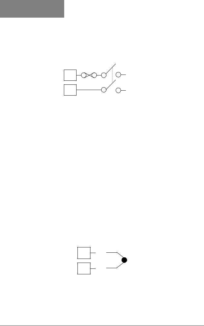
DCP200 Profile Controller & Recorder - Product Manual
Power Connections - 24/48V AC/DC Powered Instruments
24/48V AD/DC powered instruments will operate from a 20 to 48V AC or 22 to 55V DC supply. AC power consumption is 15VA max, DC power consumption is 12 watts max. Connection should be via a two-pole IEC60947-1 & IEC60947-3 compliant isolation switch / circuit breaker and a UL listed fuse type: 65v dc 1Aamp anti-surge.
13 |
_ |
14 |
+ |
Figure 10. 24/48V AC/DC Power Connections
WARNING:
CHECK THE INFORMATION LABEL ON THE CASE TO DETERMINE THE CORRECT VOLTAGE BEFORE CONNECTING TO A LIVE SUPPLY.
CAUTION:
This equipment is designed for installation in an enclosure that provides adequate protection against electric shock. The isolation switch should be located in close proximity to the unit, in easy reach of the operator and appropriately marked.
Universal Input Connections
Universal Input Connections - Thermocouple (T/C)
Use only the correct thermocouple wire or compensating cable from the probe to the instrument terminals avoiding joints in the cable if possible. Where joints are made, special thermocouple connectors must be used. Failure to use the correct wire type and connectors will lead to inaccurate readings. Ensure correct polarity of the wires by cross-referencing the colours with a thermocouple reference table.
3 _
2 +
Figure 11. Thermocouple Input Connections
51-52-25-150, Issue 1 – April 2009 |
Electrical Installation |
Page 27 |

DCP200 Profile Controller & Recorder - Product Manual
Universal Input Connections – PT100 / NI120 (RTD) input
For three wire RTDs, connect the resistive leg and the common legs of the RTD as illustrated. For a two wire RTD a wire link should be used in place of the third wire (shown by dotted line). Two wire RTDs should only be used when the leads are less than 3 metres long.
Avoid cable joints.
3
2


 RTD 1
RTD 1 
Figure 12. RTD Input Connections
Four wire RTDs can be used, provided that the fourth wire is left unconnected. This wire should be cut short or tied back so that it cannot contact any of the terminals on the rear of the instrument.
Universal Input Connections - Linear Volt, mV or mA input
Linear DC voltage, millivolt or milliamp input connections are made as illustrated. Carefully observe the polarity of the connections.
3 |
|
_ |
+ |
|
|||
|
|
|
|
|
|
|
|
|
|
|
|
2 |
|
|
|
+ |
|
||
|
|
||
|
|
|
_ |
1 |
|
mV/V |
|
|
|||
|
|
mA |
|
|
|
||
Figure 13. DC Volt, mV & mA Input Connections
Page 28 |
Electrical Installation |
51-52-25-150, Issue 1 – April 2009 |

DCP200 Profile Controller & Recorder - Product Manual
Option Slot 1 Connections
Option Slot 1 – Single Relay Output Module
If option slot 1 is fitted with a single relay output module, make connections as illustrated.
The relay contacts are SPDT and rated at 2 amps resistive, 240 VAC.
19  N/C
N/C
20  COM
COM
21  N/O
N/O
Figure 14. Option Slot 1 – Single Relay Module
Option Slot 1 – Single SSR Driver Output Module
If option slot 1 is fitted with a single SSR driver output module, make connections as illustrated. The solid-state relay driver is a 0-10V DC signal, load impedance must be no less than 500 ohms. SSR driver outputs are not isolated from the signal input or other SSR driver outputs.
19  _
_
20
21 +
+
Figure 15. Option Slot 1 – Single SSR Driver Module
Option Slot 1 - Triac Output Module
If option slot 1 is fitted with a Triac output module, make connections as shown. This output is rated at 0.01 to 1 amp @ 280V AC 50/60Hz. A snubber should be fitted across inductive loads to ensure reliable switch off the Triac.
20
21
Figure 16. Option Slot 1 - Triac Module
51-52-25-150, Issue 1 – April 2009 |
Electrical Installation |
Page 29 |

DCP200 Profile Controller & Recorder - Product Manual
Option Slot 1 - Linear Voltage or mADC Output module
If option slot 1 is fitted with a DC linear output module, make connections as illustrated.
19 _
20
21 +
+
Figure 17. Option Slot 1 - Linear Voltage & mADC Module
Option Slot 2 Connections
Option Slot 2 – Single Relay Output Module
If option slot 2 is fitted with a single relay output module, make connections as illustrated. The relay contacts are SPDT, and rated at 2 amps resistive, 240 VAC.
22 N/C
23  COM
COM
24  N/O
N/O
Figure 18. Option Slot 2 – Single Relay Module
Option Slot 2 - Dual Relay Output Module
If option slot 2 is fitted with a dual relay output module, make connections as illustrated. This module has two independent SPST relays, which share a common connection terminal. The contacts are rated at 2 amp resistive 240 VAC.
22 |
|
N/O OUTPUT 2B |
|
||
|
|
|
23 COMMON
24 |
|
N/O OUTPUT 2A |
|
||
|
|
|
Figure 19. Option Slot 2 - Dual Relay Module
Page 30 |
Electrical Installation |
51-52-25-150, Issue 1 – April 2009 |
Loading...