


C7189U Remote Indoor Sensor
(USE WITH VISIONPRO® THERMOSTATS)
INSTALLATION INSTRUCTIONS
APPLICATION
This indoor sensor is designed to sense temperature at a remote location and send this information to the VisionPRO Thermostat. This sensor can be used as a stand alone sensor or as part of an averaging network. Once a remote indoor temperature sensor is connected to the thermostat, the thermostat's sensor is no longer used. The thermostat's installer setup should be modified to tell the thermostat that remote indoor temperature sensor(s) have been used. The Inside temperature reading on the thermostat's display will be the remote sensor(s) temperature location(s).
M24055
Fig. 1. C7189U Remote Indoor Sensor
SPECIFICATIONS
Operating Ambient Temperature Range:
45 to 88°F (7.2 to 32°C).
Display Range:
0 to 99°F (-18 to 37°C).
Sensor Accuracy:
+/-1.5°F at 70°F (+/-.84 at 21°C)
Operating Relative Humidity:
5% to 95% non-condensing.
Finish:
White.
Resistance Characteristics:
Negative temperature coefficient (NTC). Resistance decreases as the temperature increases.
Dimensions in inches (mm):
1 1/2 (38) wide x 2 1/4 (57) high x 3/4 (19) deep.
Distance:
Maximum distance between thermostat and sensor is 200 feet.
Must be installed by a trained, experienced technician
•Read these instructions carefully. Failure to follow these instructions can damage the product or cause a hazardous condition.
•Check the specification in this booklet to verify that this product is suitable for the application.
•Always test for proper operation after installation
69-1710EFS-1
C7189U REMOTE INDOOR SENSOR
INSTALLATION
Installation Tips
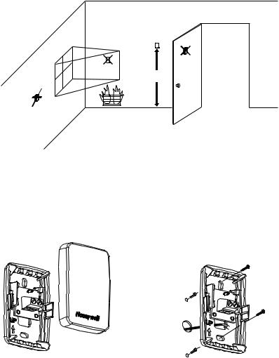
Install the sensor about 5 feet (1.5m) above the floor in an area with good air circulation at average temperature. Maximum distance between remote sensor and the thermostat is 200 feet. See Fig. 2.
 CAUTION
Electrical Hazard
Can cause electrical shock or equipment damage. Disconnect power before beginning installation.
YES
NO
NO
5 FEET
(1.5 METERS)
NO
M24115
Fig. 2. Typical location for C7189U Sensor.
Remote Sensor Wallplate Installation
Remove the cover from the remote sensor as shown in Fig. 3.
1.Pull wires through wire hole.
2.Position wallplate on wall, level and mark screw hole positions with pencil.
3.Drill holes at marked positions, then tap in supplied wall anchors.
4.Place wallplate over anchors, insert and tighten mounting screws. See Fig. 4.
M24056
Fig. 3. Remove the cover.
M24057
Fig. 4. Mount wallplate to wall.
69-1710EFS-1 |
2 |

C7189U REMOTE INDOOR SENSOR
WIRING
The sensor can be used to provide one remote sensor (see Fig. 6) or as a temperature averaging network with multiple sensors connected (see Fig. 7). The thermostat is not part of the average network.
 CAUTION
ELECTRICAL HAZARD.
Can cause electrical shock or equipment damage. Disconnect power before wiring.
1.Run the wire cable from the thermostat to the remote sensor location.
2.Loosen screw terminals, insert wires into terminal block (polarity does not matter), then retighten screws.
3.Push excess wire back into the wall opening.
4.Plug the wall opening with non-flammable insulation to prevent drafts from affecting the sensor operation and replace the cover on the remote sensor.
5.Connect the two wires to the thermostat's remote sensor terminals (polarity does not matter) and replace the thermostat back onto the wallplate. See Fig. 6.
M24116
Fig. 5. Terminal block wiring.
|
|
|
C7189 |
|
|
3 |
2 |
|
|
|
|
Y2 |
RC |
|
1 |
|
R |
|
|
|
W |
|
R |
W2 |
Y |
|
C |
S1 |
G |
|
|
S2 |
C |
|
|
1POWER SUPPLY. PROVIDE DISCONNECT MEANS AND OVERLOAD PROTECTION AS REQUIRED.
2IF MORE THAN ONE C7189 REMOTE SENSOR IS REQUIRED, REFER TO FIGURE 7.
3WIRES MUST HAVE A CABLE SEPARATE FROM THE
THERMOSTAT CABLE. |
M19972A |
Y2 |
|
|
2 |
2 |
1 |
1 |
C7189 |
|
S2 |
C7189 |
|
|
|
|
|
C7189 |
C7189 |
Y2 |
|
|
2 |
|
1 |
12
2C7189 C7189 C7189
C7189 C7189 C7189
Fig. 6. Wiring a single C7189U Sensor.
C7189 C7189 C7189
1 SENSORS MUST BE ARRANGED IN THIS CONFIGURATION TO OPERATE CORRECTLY.
2 WIRES MUST HAVE A CABLE SEPARATE FROM THE
THERMOSTAT CABLE. |
M19973 |
Fig. 7. Wiring Multiple C7189U Sensors.
OPERATION
Once a remote indoor temperature sensor is connected to |
. |
the thermostat, the thermostat's sensor is no longer used. |
|
The thermostat's installer setup should be modified to tell |
|
the thermostat that remote indoor temperature sensor(s) |
|
have been used. The Inside temperature reading on the |
|
thermostat's display will be the remote sensor(s) |
|
temperature location(s). See Fig. 8. |
|
TUE
FAN |
CHANGE FILTER UV LAMP HUMIDIFIER PAD |
||
Inside |
Set To |
||
|
|||
AUTO
Heat On
SYSTEM |
Following |
|
Schedule |
HEAT |
|
|
AM |
SCHED HOLD CLOCK SCREEN MORE
M19974
Fig. 8. Inside Temperature Reading on TH8000 Series Thermostat.
3 |
69-1710EFS-1 |

C7189U REMOTE INDOOR SENSOR
CHECKOUT
For best results, allow the sensor to absorb the air moving through the room for a minimum of twenty minutes before taking a resistance measurement.
1.Use an accurate thermometer (+/-1ºF[0.5ºC]) measure the temperature at the sensor location.
2.Remove one wire from one of the sensor's wiring terminals. Use an ohmmeter to measure the resistance across the sensor. Verify the sensor accuracy with the temperature/resistance in Table 1.
CALIBRATION
The sensor is calibrated at the factory and cannot be recalibrated in the field.
Table 1. Sensor Resistance at Room Temperature.
Room Temperature |
Ohms of |
|
°F |
°C |
Resistance |
|
|
|
40 |
4.4 |
22537 |
42 |
5.6 |
21516 |
|
|
|
44 |
6.7 |
20546 |
|
|
|
46 |
7.8 |
19626 |
|
|
|
48 |
8.9 |
18754 |
|
|
|
50 |
10.0 |
17926 |
|
|
|
52 |
11.1 |
17136 |
|
|
|
54 |
12.2 |
16387 |
|
|
|
56 |
13.3 |
15675 |
|
|
|
58 |
14.4 |
14999 |
|
|
|
60 |
15.6 |
14356 |
|
|
|
62 |
16.7 |
13743 |
|
|
|
64 |
17.8 |
13161 |
|
|
|
66 |
18.9 |
12607 |
|
|
|
68 |
20.0 |
12081 |
|
|
|
70 |
21.1 |
11578 |
|
|
|
72 |
22.2 |
11100 |
|
|
|
74 |
23.3 |
10644 |
|
|
|
76 |
24.4 |
10210 |
|
|
|
78 |
25.6 |
9795 |
|
|
|
80 |
26.7 |
9398 |
|
|
|
82 |
27.8 |
9020 |
|
|
|
84 |
28.9 |
8659 |
|
|
|
86 |
30.0 |
8315 |
|
|
|
88 |
31.1 |
7986 |
|
|
|
90 |
32.2 |
7672 |
|
|
|
92 |
33.3 |
7372 |
|
|
|
94 |
34.4 |
7086 |
|
|
|
96 |
35.6 |
6813 |
|
|
|
98 |
36.7 |
6551 |
|
|
|
100 |
37.8 |
6301 |
|
|
|
Automation and Control Solutions |
|
|
|
|
Honeywell International Inc. |
Honeywell Limited-Honeywell Limitée |
|
|
|
1985 Douglas Drive North |
35 Dynamic Drive |
|
|
|
Golden Valley, MN 55422 |
Scarborough, Ontario M1V 4Z9 |
|
|
|
|
|
|
||
http://yourhome.honeywell.com |
|
|
|
|
|
|
|
|
® U.S. Registered Trademark
© 2005 Honeywell International Inc. Patents Pending.
69-1710EFS-1 M.S. Rev. 10-05
 Loading...