


Hydronic Zoning Thermostat
AQ1000TN2
OWNER’S GUIDE


 Place
Place


 Bar
Bar
 Code
Code
 Here
Here


Need Help?
For assistance with this product please visit http://yourhome.honeywell.com or call Honeywell Customer Care toll-free at 1-800-468-1502.
Read and save these instructions.
®U.S. Registered Trademark. Patents pending.
©9-06 Honeywell International Inc. All rights reserved.
69-2005EF

Table of contents
User’s section |
|
About your new thermostat.................................................................................... |
1 |
Screen display ....................................................................................................... |
2 |
Power-up / modes of operation.............................................................................. |
3 |
User’s configuration menu..................................................................................... |
4 |
Temperature display and setting............................................................................ |
6 |
Installer’s section |
|
Installation.............................................................................................................. |
7 |
Configuration switches........................................................................................... |
8 |
Installer’s configuration menu................................................................................ |
9 |
Appendix |
|
Technical specifications ....................................................................................... |
12 |
2-year limited warranty ........................................................................................ |
13 |
69-2005EF

About your new thermostat
Honeywell’s AQ1000TN2 hydronic zoning thermostat can be used to control the ambient air temperature or floor temperature. You can choose among the following temperature control modes (see page 8):
A mode: • controls and displays the ambient air temperature
F mode: • controls and displays the floor temperature using an external temperature sensor
AF mode: • controls and displays the ambient air temperature
•maintains the floor temperature within desired limits using an external temperature sensor
Screen
Temperature adjustment buttons
Backlight button
1 |
69-2005EF |
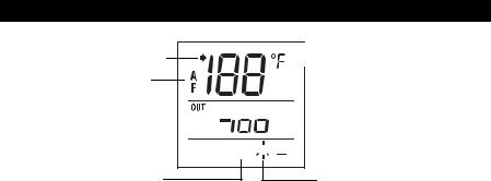
Screen display
The arrow appears when the setpoint is displayed
Temperature control mode
Heating is On 


Freeze Protection mode (see next page)
 Indoor temperature


 Outdoor temperature 1


 Keypad lock 2
Comfort / Unoccupied mode (see next page)
1The outdoor temperature will be displayed only if the data is available.
2This icon appears to indicate that the thermostat settings cannot be modified as the hydronic
zoning controller has locked the keypad. The backlight  button and the
  buttons can still be used to activate the backlight and to display the setpoint.
2 |
69-2005EF |
Power-up / modes of operation
The thermostat is powered through the wires connecting it to the AQ2000 Series hydronic zoning controller. Therefore, the thermostat turns on when the controller is powered. The thermostat can be placed in one of the 3 following modes of operation:
Comfort Mode
The thermostat is normally in the Comfort mode. In this mode, the temperature is set using the  buttons.
Unoccupied Mode
When the Unoccupied mode is activated by the hydronic zoning controller, the temperature setpoint is lowered by the temperature setback value. This value is set in the User’s configuration menu (see page 5).
Freeze Protection Mode
When the Freeze Protection mode is activated by the hydronic zoning controller, the thermostat is placed at the Freeze Protection temperature. This value is set in the Installer’s configuration menu (see page 10).
3 |
69-2005EF |

User’s Configuration Menu
1.Press the backlight  button for 3 seconds to access the configuration menu. The first parameter is displayed.
2.To modify a parameter, press either of the  buttons.
3.To display the next parameter, briefly press the backlight  button.
4.To exit the menu, press the backlight  button for 3 seconds.
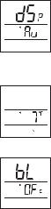
The parameters appear in the order shown in the following table.
Parameter |
Default setting |
Options |
|
|
|
Display mode |
Automatic |
Automatic, °F, °C |
|
|
|
Temperature setback |
7 °F (4 °C) |
0 to 16 °F (0 to 9 °C) |
|
|
|
Backlight |
Temporary |
Temporary / Permanent |
|
|
|
4 |
69-2005EF |
Display Format
Use this parameter to choose the temperature display mode. When the automatic mode is selected, the thermostat displays the temperature format set on the hydronic zoning controller. If °F or °C is selected, the thermostat displays the temperature in the selected format respectively.
Temperature Setback
When the Unoccupied mode is activated by the hydronic zoning controller (certain controller models only), the temperature setpoint is lowered (set back). Use this parameter to specify the amount of temperature setback.
Backlight
Use this parameter to choose between temporary and permanent backlight. When temporary backlight is selected, the screen is lit for 12 seconds every time any button is pressed.
5 |
69-2005EF |

Temperature Display and Setting
The thermostat generally displays the actual (measured) temperature. To display the setpoint temperature, press one of the  buttons once. The setpoint will be displayed for the next 5 seconds. An arrow appears at the left of the setpoint temperature display.
To change the setpoint, press one of the  buttons until the desired temperature is displayed. To scroll faster, press and hold the button.
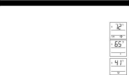
Error Messages
The measured temperature is below the thermostat’s display range.
The measured temperature is above the thermostat’s display range.
Verify the thermostat and external (floor) sensor connections.
6 |
69-2005EF |

Installation
1.Remove the faceplate from the base by unscrewing the screw underneath the thermostat and tilting the bottom of the faceplate up. Note that the screw remains captive on the base.
2.Insert the wires through the center hole of the base and secure the base to the wall or onto an electrical box.
3.Connect the wires to the terminals (no polarity to observe).
|
Terminal |
Description |
|
|
|
|
|
1 |
TH |
AQ2000 Series hydronic zoning controller connections |
|
|
|
||
2 |
TH |
||
|
|||
|
|
|
|
3 |
SENSOR |
External sensor connections for floor temperature |
|
|
|
measurement (required only if the thermostat is set to F |
|
4 |
SENSOR |
||
or AF mode; see pages 1 and 8) |
|||
|
|
||
|
|
|
4.Set the configuration switches (see next page).
5.Re-attach the faceplate to the base and secure with the captive screw.
NOTE: Keep the thermostat's air vents clean and unobstructed at all times.
7 |
69-2005EF |
Configuration switches
The configuration (DIP) switches are located behind the thermostat faceplate.
NOTE : DIP switch 1 is not used.
Installer Configuration Menu (switch 2)
Use DIP switch 2 to set the thermostat in either Installer or User mode.
Temperature Control Mode (switches 3 & 4)
Use DIP switches 3 and 4 to select the temperature control mode (A, F or AF).
NOTE : F or AF mode should be used only when an external (floor) sensor is connected to the thermostat (see page 7).
8 |
69-2005EF |
 Loading...