


Excel 500/600
CONTROL SYSTEM
INSTALLATION INSTRUCTIONS |
||
|
|
CONTENTS |
Revision Overview........................................................................................................................................................................ |
|
4 |
Safety Instructions ....................................................................................................................................................................... |
|
5 |
MOUNTING .................................................................................................................................................................................... |
|
6 |
Control Unit Installation ............................................................................................. |
|
6 |
Excel 500/600 Housing Layout (not XCL5010) ......................................................... |
|
6 |
Excel 500/600 Internal Bus Wiring (not XCL5010).................................................... |
|
6 |
Module Locations (not XCL5010).............................................................................. |
|
7 |
Coding the Terminal Block (not XCL5010)................................................................ |
|
7 |
Setting the Module Address (not XCL5010).............................................................. |
|
8 |
Installation Inside a Control Panel............................................................................. |
|
8 |
Excel 500/600....................................................................................................... |
|
8 |
Excel 500-XCL5010............................................................................................ |
|
10 |
Excel 500-XCL5010 Communication Module ..................................................... |
|
10 |
Installation through a Control Panel Door (not XCL5010) ....................................... |
10 |
|
External Installation of XI582AH Operator Interface |
............................................... |
11 |
Deactivating Backlit Display of the XI582AH........................................................... |
|
12 |
Distributed I/O Installation ....................................................................................... |
|
13 |
Dimensions ............................................................................................................. |
|
14 |
Excel 500/600..................................................................................................... |
|
14 |
Excel 500-XCL5010............................................................................................ |
|
15 |
XI582AH ............................................................................................................. |
|
16 |
Battery Activation during Commissioning (XC6010, only) ....................................... |
17 |
|
Replacing the Battery.............................................................................................. |
|
17 |
Dismantling the Control Panel Unit ......................................................................... |
|
18 |
Dismantling the Control Panel Door Unit................................................................. |
|
18 |
Dismantling the Housing Cover............................................................................... |
|
18 |
Dismantling the Excel 500-XCL5010 Control Panel Unit......................................... |
18 |
|
Dismantling the XI582AH Operator Interface .......................................................... |
|
19 |
Electrical Connections ............................................................................................................................................................... |
|
20 |
Cable Routing ......................................................................................................... |
|
20 |
Shielding Input / Output Module and Power Supply Cables.................................... |
20 |
|
Shielding of Data-Transmitting Cables.................................................................... |
|
20 |
Grounding (XC5010C / XC6010, only).................................................................... |
|
20 |
System Ground ....................................................................................................... |
|
20 |
RFI Suppression ..................................................................................................... |
|
20 |
XC5010C / XC6010 Cable Lengths and Sizes........................................................ |
|
21 |
Lightning Protection ................................................................................................ |
|
21 |
Summary of Internal Modules ................................................................................. |
|
22 |
® U.S. Registered Trademark |
|
|
Copyright © 2002 Honeywell Inc. • All Rights Reserved |
EN1R-1047GE51 R0902 / 95-7524-3 |
|
EXCEL 500/600 INSTALLATION INSTRUCTIONS |
|
Line Power Supply ............................................................................................. |
23 |
XC6010 Computer Module................................................................................. |
23 |
XC5010C Computer Module .............................................................................. |
24 |
XP502 Power Supply Module............................................................................. |
25 |
XP502 with External UPS XAPU 24-2F (Internal Modules, Only)....................... |
25 |
XP502 with External UPS XAPU 24-2F (Distributed I/O Modules, Only)............ |
26 |
XP502 with External UPS XAPU 24-2F (Distributed I/O and Internal Modules) . 27 |
|
XF521A Analog Input Module ............................................................................ |
27 |
XF526 Analog Input Module............................................................................... |
28 |
XF523A Digital Input Module.............................................................................. |
29 |
XF522A and XF527 Analog Output Modules ..................................................... |
30 |
XF524A and XF529 Digital Output Modules....................................................... |
30 |
XF525A Three-Position Output Module.............................................................. |
31 |
Excel 500-XCL5010................................................................................................ |
32 |
Serial Port .......................................................................................................... |
32 |
MMI Connection ................................................................................................. |
32 |
Power Supply ..................................................................................................... |
32 |
Screw Terminal Block Installation Procedure ..................................................... |
33 |
Pull-Up Resistor Handling (O.S. 2.04.00 or higher, except for XFL521A) .......... |
34 |
Communications ........................................................................................................................................................................ |
36 |
LONWORKS Bus Wiring ............................................................................................ |
36 |
LONWORKS Bus Termination............................................................................... |
36 |
System Bus (C-Bus) ............................................................................................... |
37 |
Submodule Selection (XC6010) ......................................................................... |
37 |
System Bus Cable Specification......................................................................... |
37 |
C-Bus Extension by Using Repeaters ................................................................ |
38 |
C-Bus Termination (Excel 600) .......................................................................... |
38 |
C-Bus Termination (Excel 500) .......................................................................... |
38 |
C-Bus Termination (Excel 500-XCL5010) .......................................................... |
38 |
Excel 600 Cable Specifications............................................................................... |
39 |
Excel 500 Cable Specifications............................................................................... |
40 |
Excel 500-XCL5010 Cable Specifications .............................................................. |
41 |
MMI Cables ........................................................................................................ |
41 |
Modem or ISDN Terminal Adapter Connections ................................................ |
41 |
Changing Between MMI and Modem Connection .............................................. |
41 |
Remote Communications .......................................................................................................................................................... |
43 |
Modem or ISDN Terminal Adapter Connections..................................................... |
43 |
Modem Requirements ............................................................................................ |
43 |
No Set-up for Standard Modem Behavior .......................................................... |
43 |
Automatic Baudrate Synchronization ................................................................. |
44 |
Auto / Manual Answer Detection ........................................................................ |
44 |
Resetting the Modem ......................................................................................... |
44 |
Set-up for Special Modem Behavior................................................................... |
44 |
Set-up for In-house Telephone Systems ............................................................ |
44 |
Set-up for Limited Communication Speed.......................................................... |
44 |
Troubleshooting.................................................................................................. |
44 |
TCP/IP Dial-Up via TCP/IP Modem XM500 ............................................................ |
44 |
GSM Communication (Europe, only) ...................................................................... |
44 |
M20T Safety Precautions ................................................................................... |
45 |
Required Third-Party Equipment ............................................................................ |
45 |
Serial Cable........................................................................................................ |
46 |
GSM Antenna Requirements ............................................................................. |
46 |
Antenna Examples ............................................................................................. |
46 |
EN1R-1047GE51 R0902 |
2 |
|
EXCEL 500/600 INSTALLATION INSTRUCTIONS |
GSM Antenna Installation |
.......................................................................................47 |
M20 Terminal Set-up............................................................................................... |
47 |
Trademark Information Echelon, LON, LONMARK, LONWORKS, LonBuilder, NodeBuilder, LonManager, LonTalk, LonUsers, LonPoint, Neuron, 3120, 3150, the Echelon logo, the LONMARK logo, and the LonUsers logo are trademarks of Echelon Corporation registered in the United States and other countries. LonLink, LonResponse, LonSupport, and LonMaker are trademarks of Echelon Corporation.
3 |
EN1R-1047GE51 R0902 |
EXCEL 500/600 INSTALLATION INSTRUCTIONS
REVISION OVERVIEW
On the following pages, changes have been made compared to the previous release of this document:
Page: |
Change: |
throughout |
Information regarding Distributed I/O modules has been removed. Please refer instead to |
|
Distributed I/O Product Data (EN0B-0090GE51). |
21 |
Fig. 44 has been changed. |
23 |
Fig. 45 has been changed. |
27 |
The technical specifications of the XF521A analog input module have been expanded and |
|
Table 7 and Table 8 added. |
30 |
The technical specifications of the XF522A and XF527 analog output modules have been |
|
expanded. |
34 |
Section "Pull-Up Resistor Handling (O.S. 2.04.00 or higher, except for XFL521A)" has been |
|
added. |
EN1R-1047GE51 R0902 |
4 |

EXCEL 500/600 INSTALLATION INSTRUCTIONS
SAFETY INSTRUCTIONS
—When performing any work (installation, mounting, startup), all instructions given by the manufacturer and in particular the safety instructions provided in the Installation Instructions are to be observed.
—The Excel 500/600 controller may be installed and mounted only by authorized and trained personnel.
—If the unit is modified in any way, except by the manufacturer, all warranties concerning operation and safety are invalidated.
—Make sure that certain local standards and regulations are observed at all times. Examples of such regulations are VDE 0800 and VDE 0100.
—Use only accessory equipment which comes from or has been approved by Honeywell.
 CAUTION
Disconnect the power supply before you start to install the Excel 500/600 Controller. Do not reconnect the power supply until you have completed installation.
 CAUTION
Disconnect the power supply before plugging in or removing the communication module (Excel 500 XCL5010).
5 |
EN1R-1047GE51 R0902 |
EXCEL 500/600 INSTALLATION INSTRUCTIONS
MOUNTING
Control Unit Installation
The Excel 500 and 600 controllers have the same housing and can be installed two different ways:
—Installation inside a control panel (see page 8).
—Installation through a control panel door (see page 10).
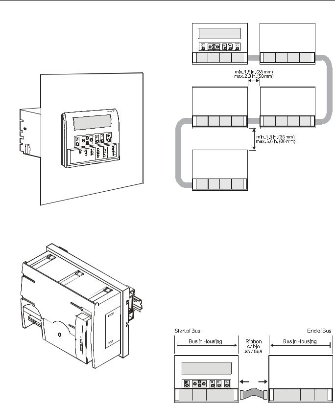
Fig. 1. Excel 500/600 panel door mounting
The Excel 500-XCL5010 can be mounted only on a DIN rail; control panel door installation is not possible.
Fig. 3. Up to five housings can be connected together
When housings are alongside one another, a minimum spacing of 1.5 in. (35 mm) should be taken into consideration to enable the hinged cover to be opened. The maximum spacing between housings is limited by tailor-made internal bus cables as shown in Fig. 3.
Excel 500/600 Internal Bus Wiring (not XCL5010)
Each housing has four plug-in module locations. The individual modules are connected by an internal bus in the housing.
Configurations comprising more than one housing must have the individual busses in the housings connected to one another.
Fig. 2. Excel 500-XCL5010 DIN rail mounting
Excel 500/600 Housing Layout (not XCL5010)
A controller comprises from one to a maximum of five housings. The housings may be fitted alongside one another or, one above the other. Any combination is possible.
Fig. 4. Excel 500/600 bus wiring
The connection is made via tailor-made ribbon cables. Two different types are available:
—Type XW568 3 in. (80 mm) long (for housings alongside one another)
EN1R-1047GE51 R0902 |
6 |
EXCEL 500/600 INSTALLATION INSTRUCTIONS
—Type XW569 13 in. (330 mm) long (for housings one above the other)
 CAUTION
Incorrectly inserted bus cables can destroy the modules installed.
The internal bus begins at the first housing, containing the power supply and computer modules, and ends at the last housing.
The protective bus connection covers must be removed.
Table 1. Internal module locations
Module |
|
Type |
|
Module location |
CPU |
|
XC5010C / |
|
1st housing, location 4 |
|
|
XC6010 |
|
|
Power |
|
XP502 |
|
1st housing, location 1 |
supply |
|
|
|
|
AI |
|
XF521A / XF526 |
|
any |
|
|
|
|
|
AO |
|
XF522A / XF527 |
|
any |
DI |
|
XF523A |
|
any |
DO |
|
XF524A / XF529 |
|
not in the 1st housing |
3-position |
|
XF525A |
|
not in the 1st module |
output |
|
|
housing |
|
|
|
|
Coding the Terminal Block (not XCL5010)
The terminal block is coded with pins to prevent mixing the module types during commissioning or servicing. Mixing the modules can damage them.
You can code the terminal block by inserting pins into designated location holes on the terminal block in the base.
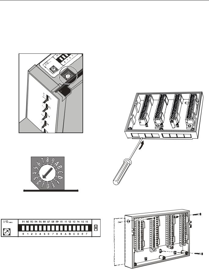
Fig. 5. Removal of bus connection cover
The overall internal bus length (bus cable and bus in the housings) must not exceed 6 ft (2m).
Bus cables must be routed at least 2 in. (50 mm) away from power cables to prevent possible inductive and capacitive interference.
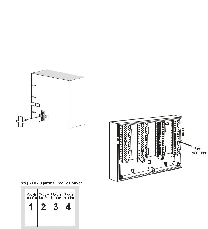
Module Locations (not XCL5010)
Each housing has four plug-in module locations.
Fig. 6. Internal module numbering
Table 1 shows the plug-in location to which each module may be assigned:
Fig. 7. Inserting the code pin in the terminal block
Table 2 shows the coding pin positions for the individual module types:
Table 2. Code pin position by module type
Module |
Type |
Pin position |
CPU |
XC5010C, XC6010 |
08 |
|
|
|
Power supply |
XP502 |
06 |
AI |
XF521A, XF526 |
07 |
AO |
XF522A, XF527 |
11 |
DI |
XF523A |
09 |
DO |
XF524A, XF529 |
10 |
|
|
|
3-position output |
XF525A |
12 |
|
|
|
NOTE: Distributed I/O modules are coded differently. See Distributed I/O Product Data (EN0B-0090GE51).
7 |
EN1R-1047GE51 R0902 |
EXCEL 500/600 INSTALLATION INSTRUCTIONS
Setting the Module Address (not XCL5010)
In the case of application prior to CARE 4.0, you can set the module address using the rotary HEX switches located on the upper surface of the respective input and output modules. The rotary HEX switch of Distributed I/O modules is situated within the housing. The XP502 power supply module and the XC5010C / XC6010 computer modules do not need a hardware address.
Fig. 8. Internal module HEX switch location
The 16 I/O modules (max. including Distributed I/O) are addressed by means of the rotary HEX switch settings 0 to F.
Fig. 9. Close-up of HEX addressing switch
The relationship between the rotary HEX switch and the module address can be seen on the label located next to the rotary HEX switch.
Fig. 10. HEX switch label
Care should be taken to ensure that each module gets its own module address. Addressing the modules in ascending order 0 through F is recommended for the sake of clarity for maintenance personnel.
 CAUTION
Unplugging a module before switching OFF the power supply could destroy the module. Do not unplug modules with the power still connected. First switch S1 on the power supply module to the 0 position.
Installation Inside a Control Panel
Excel 500/600
IMPORTANT
Observe the minimum spacing of 1.5 in. (35 mm) when installing more than one housing. Do not exceed the maximum spacing; otherwise, the tailormade internal bus cables will be too short.
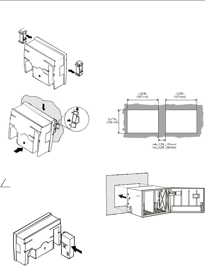
1. Break off cable entry strip segments.
Fig. 11. Cable entry strip segments
2. Install the base.
Fig. 12. Installing the base in the panel
EN1R-1047GE51 R0902 |
8 |

EXCEL 500/600 INSTALLATION INSTRUCTIONS
3.Code the terminal block (see section "Coding the Terminal Block (not XCL5010)" on page 7).
4.Make sure that the locking screws are positioned as shown in Fig. 13.
5.Plug in the enclosure.
Fig. 13. Housing locking screws and latches
6.Shift latches inwards until the housing is released.
7.Set the module addresses (see section "Setting the Module Address (not XCL5010)" on page 8).
8.Insert the modules.
Fig. 14. Modules and ribbon cable
9.Plug the ribbon cable onto the computer module.
10.Close the cover.
Extended wiring base (wall-mounting, only; US, only):
As an alternative to the base plate, an extended wiring base may be used. This is available for the U.S. market, only, and can be ordered without cover plate (OS No. 14507274-001) or with cover plate (OS No. 14507274-002).
Fig. 15. Excel 500/600 extended wiring base
Using the extended wiring base the I/O terminals are accessible at run-time.
9 |
EN1R-1047GE51 R0902 |
EXCEL 500/600 INSTALLATION INSTRUCTIONS
Excel 500-XCL5010
1.Attach the DIN rail mounting clips to the housing.
2.Mount the controller on the DIN rail.
1 |
0000079a |
|
1
2 
3
Fig. 16. Mounting Excel 500-XCL5010 on DIN rail
Excel 500-XCL5010 Communication Module
 CAUTION
Always plug in the communication module before connecting the power supply.
Always disconnect the power supply before unplugging the communication module.
0000043a
Plug in the communication module until it snaps into the con troller housing
NOTE: If the communication module has been replaced or pulled out and plugged in again, push the reset button after power on.
Installation through a Control Panel Door (not XCL5010)
IMPORTANT
Observer the minimum spacing of 1.5 in. (35 mm) when installing more than one housing. Do not exceed the maximum spacing; otherwise, the tailormade internal bus cables will be too short.
1, Prepare the door in accordance with the following. dimensions.
Fig. 18. Panel door mounting dimensions
2. Insert the housing.
Fig. 19. Inserting the housing in the panel door
3. Insert the retaining clamp.
Fig. 17. Inserting the communication module
EN1R-1047GE51 R0902 |
10 |
EXCEL 500/600 INSTALLATION INSTRUCTIONS
Fig. 20. Housing retaining clamp
4.Turn retaining clamp to fix housing.
5.Code the terminal block (see page 7).
6.Install the base.
Fig. 21. Installing the wiring base
7.Complete electrical wiring.
8.Lock the cover.
Fig. 22. Locking the MMI cover
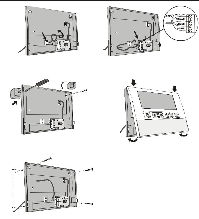
External Installation of XI582AH Operator
Interface
1. Remove the cover.
Fig. 23. Loosening the cover
Fig. 24. Removing cover
2.If mounting on a wall, disconnect cable from panel for easier handling.
Fig. 25. Disconnecting cable from cover
3.Route cable from the computer module (XC6010, XC5010C, XCL5010).
11 |
EN1R-1047GE51 R0902 |
EXCEL 500/600 INSTALLATION INSTRUCTIONS
Fig. 26. Routing the cable
4. If mounting on a wall, remove feet.
Fig. 27. Removing feet
5. Attach the housing to the wall.
Fig. 28. Attaching to wall
6.Make electrical connections (gray wire not used).
7.Reconnect cable to panel if removed in step 2.
Fig. 29. Making electrical connections
8. Reattach the cover.
Fig. 30. Reattaching cover
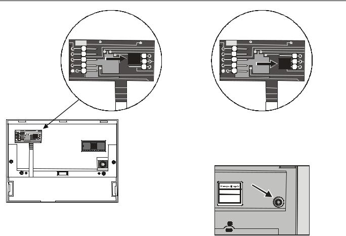
Deactivating Backlit Display of the XI582AH
The XI582AH Operator Interface is equipped with an integrated backlit display to suit the display to the ambient lighting conditions. By default, this backlight is ON. This can be disabled by means of a jumper if required. The jumper is located at the back of the XI582AH cover.
EN1R-1047GE51 R0902 |
12 |
EXCEL 500/600 INSTALLATION INSTRUCTIONS
Fig. 31. Jumper location (backlight ON position)
The figure above shows the location of the jumper. To change jumper position, disconnect the connector first, then pull off jumper with tweezers or pincers and move to new position.
When the jumper is enabled (ON-position) the backlight will be activated with the first key press of any of the eight operating keys. If no entries are made for approximately two minutes, the backlight turns itself off automatically until the next key is pressed again.
Fig. 32. Backlight OFF jumper position
When the jumper is disabled (OFF-position), the backlight is permanently deactivated.
The contrast of the display can be adjusted using the potentiometer at the rear of the unit.
Fig. 33. Contrast potentiometer
Distributed I/O Installation
Please refer to Distributed I/O Product Data sheet (EN0B 0090GE51) for more information.
13 |
EN1R-1047GE51 R0902 |
EXCEL 500/600 INSTALLATION INSTRUCTIONS
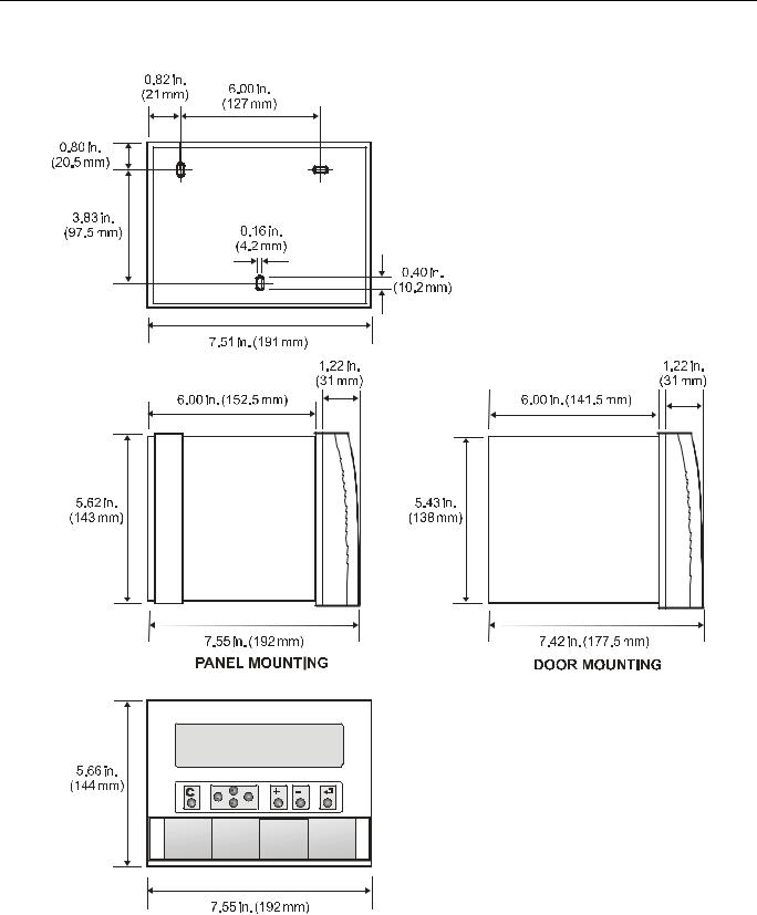
Dimensions
Excel 500/600
Fig. 34. Excel 500/600 outside dimensions
EN1R-1047GE51 R0902 |
14 |
EXCEL 500/600 INSTALLATION INSTRUCTIONS
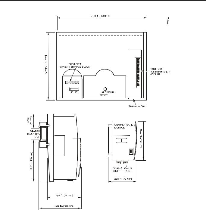
Excel 500-XCL5010
Fig. 35. Excel 500-XCL5010 dimensions
15 |
EN1R-1047GE51 R0902 |
 Loading...