


 Loading...
3800g/3800gHD/3800gPDF
General Purpose Handheld Linear Imager
User’s Guide
™

Disclaimer
Honeywell International Inc. (“Honeywell”) reserves the right to make changes in specifications and other information contained in this document without prior notice, and the reader should in all cases consult Honeywell to determine whether any such changes have been made. The information in this publication does not represent a commitment on the part of Honeywell.
Honeywell shall not be liable for technical or editorial errors or omissions contained herein; nor for incidental or consequential damages resulting from the furnishing, performance, or use of this material.
This document contains proprietary information that is protected by copyright. All rights are reserved. No part of this document may be photocopied, reproduced, or translated into another language without the prior written consent of Honeywell.
© 2006-2008 Honeywell International Inc. All rights reserved.
Other product names or marks mentioned in this document may be trademarks or registered trademarks of other companies and are the property of their respective owners.
Web Address: www.honeywell.com/aidc

Table of Contents
Chapter 1 - Getting Started
About This Manual ....................................................... |
1-1 |
Unpacking the Imager.................................................. |
1-1 |
3800g Models .............................................................. |
1-1 |
Connecting the Imager with USB................................. |
1-2 |
USB PC or Macintosh Keyboard............................ |
1-2 |
IBM SurePos .......................................................... |
1-3 |
USB HID................................................................. |
1-3 |
USB Com Port Emulation....................................... |
1-3 |
Plug and Play............................................................... |
1-4 |
Connecting the Imager When Powered by Host |
|
(Keyboard Wedge) .................................................... |
1-4 |
Keyboard Wedge Connection ................................ |
1-5 |
Laptop Direct Connect ........................................... |
1-6 |
Connecting the Imager with RS-232 Serial Port .... |
1-6 |
IBM 4683 Ports 5B, 9B, and 17 Interface............... |
1-7 |
Reading Techniques .................................................... |
1-8 |
Reading PDF417 Bar Codes.................................. |
1-8 |
Resetting the Standard Product Defaults..................... |
1-9 |
Chapter 2 - Terminal Interfaces |
|
Terminal ID .................................................................. |
2-1 |
Supported Terminals.................................................... |
2-2 |
Keyboard Country ........................................................ |
2-4 |
Keyboard Style............................................................. |
2-5 |
Keyboard Modifiers ...................................................... |
2-6 |
RS-232 Baud Rate ................................................. |
2-8 |
RS-232 Word Length: Data Bits, Stop Bits, |
|
and Parity ............................................................... |
2-8 |
RS-232 Handshaking ........................................... |
2-10 |
Chapter 3 - Output
i

Good Read Indicators.................................................. |
3-1 |
Beeper – Good Read............................................. |
3-1 |
Beeper Volume – Good Read................................ |
3-1 |
Beeper Pitch – Good Read.................................... |
3-1 |
Beeper Duration – Good Read .............................. |
3-2 |
LED – Good Read ................................................. |
3-2 |
Number of Beeps – Good Read ............................ |
3-2 |
Good Read Delay ........................................................ |
3-3 |
User-Specified Good Read Delay.......................... |
3-3 |
Trigger Modes.............................................................. |
3-3 |
Manual/Serial Trigger ............................................ |
3-3 |
Automatic Trigger .................................................. |
3-4 |
Presentation Mode................................................. |
3-4 |
Continuous Illumination Mode ............................... |
3-4 |
Hands Free Time-Out .................................................. |
3-4 |
Reread Delay............................................................... |
3-5 |
User-Specified Reread Delay ................................ |
3-5 |
Centering Window ....................................................... |
3-5 |
Output Sequence Overview......................................... |
3-8 |
Output Sequence Editor ........................................ |
3-9 |
Require Output Sequence ..................................... |
3-9 |
Output Sequence Editor ...................................... |
3-11 |
Require Output Sequence ................................... |
3-11 |
Multiple Symbols........................................................ |
3-12 |
No Read..................................................................... |
3-12 |
Video Reverse ........................................................... |
3-13 |
Chapter 4 - Data Editing |
|
Prefix/Suffix Overview.................................................. |
4-1 |
To Add a Prefix or Suffix:....................................... |
4-1 |
To Clear One or All Prefixes or Suffixes: ............... |
4-2 |
To Add a Carriage Return Suffix to All |
|
Symbologies .......................................................... |
4-3 |
Prefix Selections .................................................... |
4-3 |
Suffix Selections .................................................... |
4-4 |
Function Code Transmit ........................................ |
4-4 |
ii

Intercharacter, Interfunction, and Intermessage |
|
Delays .......................................................................... |
4-4 |
Intercharacter Delay............................................... |
4-5 |
User Specified Intercharacter Delay ...................... |
4-5 |
Interfunction Delay ................................................. |
4-6 |
Intermessage Delay ............................................... |
4-6 |
Chapter 5 - Data Formatting |
|
Data Format Editor Introduction................................... |
5-1 |
To Add a Data Format............................................ |
5-1 |
Other Programming Selections .............................. |
5-2 |
Data Format Editor Commands ............................. |
5-2 |
Data Format Editor................................................. |
5-4 |
Data Formatter ....................................................... |
5-5 |
Alternate Data Formats .......................................... |
5-5 |
Chapter 6 - Secondary Interface |
|
3800g Models .............................................................. |
6-1 |
Enabling the Secondary Interface................................ |
6-1 |
Secondary RS-232 Connection ................................... |
6-1 |
Secondary Trigger Mode ............................................. |
6-2 |
Hands Free Time-Out .................................................. |
6-2 |
Chapter 7 - Symbologies |
|
Introduction .................................................................. |
7-1 |
All Symbologies ........................................................... |
7-2 |
Message Length .......................................................... |
7-2 |
Codabar ....................................................................... |
7-3 |
Codabar Start/Stop Characters ............................. |
7-3 |
Codabar Check Character ..................................... |
7-3 |
Codabar Concatenation ......................................... |
7-4 |
Codabar Message Length...................................... |
7-5 |
iii

Code 39 ....................................................................... |
7-5 |
Code 39 Start/Stop Characters ............................. |
7-5 |
Code 39 Check Character ..................................... |
7-5 |
Code 39 Message Length...................................... |
7-6 |
Code 39 Append.................................................... |
7-6 |
Code 32 Pharmaceutical (PARAF) .............................. |
7-7 |
Full ASCII............................................................... |
7-7 |
Code 39 Code Page .............................................. |
7-8 |
Interleaved 2 of 5......................................................... |
7-8 |
Check Digit ............................................................ |
7-8 |
Interleaved 2 of 5 Message Length ....................... |
7-9 |
Code 93 ..................................................................... |
7-10 |
Code 93 Message Length.................................... |
7-10 |
Code 93 Code Page ............................................ |
7-10 |
Straight 2 of 5 Industrial (three-bar start/stop) ........... |
7-11 |
Straight 2 of 5 Industrial Message Length ........... |
7-11 |
Straight 2 of 5 IATA (two-bar start/stop) .................... |
7-11 |
............................................................................. |
7-11 |
Straight 2 of 5 IATA Message Length.................. |
7-12 |
Matrix 2 of 5............................................................... |
7-12 |
Matrix 2 of 5 Message Length ............................. |
7-12 |
Code 11 ..................................................................... |
7-13 |
Check Digits Required ......................................... |
7-13 |
Code 11 Message Length.................................... |
7-14 |
Code 128 ................................................................... |
7-14 |
ISBT 128 Concatenation...................................... |
7-14 |
Code 128 Message Length.................................. |
7-15 |
Code 128 Code Page .......................................... |
7-15 |
Code 128 Function Code Transmit...................... |
7-15 |
Telepen...................................................................... |
7-15 |
Telepen Output .................................................... |
7-16 |
Telepen Message Length .................................... |
7-16 |
iv

UPC A ........................................................................ |
7-17 |
UPC A Check Digit............................................... |
7-17 |
UPC A Number System ....................................... |
7-17 |
UPC A Addenda................................................... |
7-18 |
UPC A Addenda Required ................................... |
7-18 |
UPC A Addenda Separator .................................. |
7-18 |
UPC-A/EAN-13 |
|
with Extended Coupon Code ................................... |
7-19 |
UPC E ........................................................................ |
7-19 |
UPC E0 and UPC E1 ........................................... |
7-19 |
UPC E0 and UPC E1 Expand .............................. |
7-20 |
UPC E0 and UPC E1 Addenda Required ............ |
7-20 |
UPC E0 and UPC E1 Addenda Separator ........... |
7-20 |
UPC E0 Check Digit............................................. |
7-20 |
UPC E0 Number System ..................................... |
7-21 |
UPC E0 Addenda................................................. |
7-21 |
EAN/JAN 13............................................................... |
7-21 |
EAN/JAN 13 Check Digit...................................... |
7-22 |
EAN/JAN 13 Addenda.......................................... |
7-22 |
EAN/JAN 13 Addenda Required .......................... |
7-22 |
EAN/JAN 13 Addenda Separator......................... |
7-23 |
ISBN Translate..................................................... |
7-23 |
EAN/JAN 8................................................................. |
7-23 |
EAN/JAN 8 Check Digit........................................ |
7-24 |
EAN/JAN 8 Addenda............................................ |
7-24 |
EAN/JAN 8 Addenda Required ............................ |
7-24 |
EAN/JAN 8 Addenda Separator........................... |
7-25 |
MSI............................................................................. |
7-25 |
MSI Check Character........................................... |
7-25 |
MSI Message Length ........................................... |
7-26 |
Plessey Code............................................................. |
7-26 |
Plessey Message Length ..................................... |
7-26 |
GS1 DataBar Omnidirectional.................................... |
7-26 |
GS1 DataBar Limited ................................................. |
7-27 |
GS1 DataBar Expanded ............................................ |
7-27 |
GS1 DataBar Expanded Message Length ........... |
7-28 |
v

China Post Code........................................................ |
7-28 |
Korea Post Code ....................................................... |
7-29 |
Korea Post Message Length ............................... |
7-29 |
PosiCode ................................................................... |
7-29 |
PosiCode Message Length.................................. |
7-30 |
Trioptic Code ............................................................. |
7-30 |
Codablock F............................................................... |
7-31 |
Codablock F Message Length ............................. |
7-31 |
Code 16K................................................................... |
7-31 |
Code 16K Message Length ................................. |
7-32 |
Code 49 ..................................................................... |
7-32 |
Code 49 Message Length.................................... |
7-33 |
PDF417 (3800gHD/3800gPDF only) ......................... |
7-33 |
PDF417 Message Length .................................... |
7-33 |
MicroPDF417 (3800gHD/3800gPDF only) ................ |
7-34 |
MicroPDF417 Message Length ........................... |
7-34 |
GS1 Composite Codes .............................................. |
7-34 |
UPC/EAN Version................................................ |
7-35 |
GS1 Composite Code Message Length .............. |
7-35 |
GS1 Emulation........................................................... |
7-35 |
Chapter 8 - Interface Keys |
|
Keyboard Function Relationships ................................ |
8-1 |
Supported Interface Keys ........................................... |
8-3 |
Chapter 9 - Utilities |
|
To Add a Test Code I.D. Prefix to All Symbologies ..... |
9-1 |
Show Software Revision.............................................. |
9-1 |
Show Data Format....................................................... |
9-1 |
Resetting the Standard Product Defaults .................... |
9-1 |
Temporary Visual Xpress Configuration ...................... |
9-2 |
Chapter 10 - Visual Xpress |
|
Visual Xpress Introduction ......................................... |
10-1 |
Installing Visual Xpress from the Web ................. |
10-2 |
vi

Chapter 11 - Serial Programming Commands
Conventions ............................................................... |
11-1 |
Menu Command Syntax ............................................ |
11-1 |
Query Commands ................................................ |
11-2 |
Concatenation of Multiple Commands ................. |
11-2 |
Responses ........................................................... |
11-2 |
Examples of Query Commands ........................... |
11-3 |
Trigger Commands .................................................... |
11-4 |
Resetting the Standard Product Defaults................... |
11-4 |
Menu Commands....................................................... |
11-5 |
Chapter 12 - Product Specifications |
|
3800g Product Specifications .................................... |
12-1 |
3800gHD/3800gPDF Product Specifications ............ |
12-2 |
Chapter 13 - Maintenance |
|
Repairs....................................................................... |
13-1 |
Maintenance .............................................................. |
13-1 |
Cleaning the Device ............................................. |
13-1 |
Inspecting Cords and Connectors........................ |
13-1 |
Replacing the Interface Cable.............................. |
13-2 |
Troubleshooting ......................................................... |
13-2 |
Chapter 14 - Customer Support |
|
Technical Assistance ................................................. |
14-1 |
Online Technical Assistance ................................ |
14-1 |
Product Service and Repair ....................................... |
14-2 |
Online Product Service and Repair Assistance ... |
14-2 |
Limited Warranty........................................................ |
14-3 |
Appendix A |
|
Symbology Chart ........................................................ |
A-1 |
ASCII Conversion Chart (Code Page 1252) ............... |
A-2 |
Code Page Mapping of Printed Bar Codes................. |
A-4 |
vii

viii
Product Agency Compliance
USA
FCC Part 15 Subpart B Class B
This device complies with part 15 of the FCC Rules. Operation is subject to the following two conditions:
1.This device may not cause harmful interference.
2.This device must accept any interference received, including interference that may cause undesired operation.
This equipment has been tested and found to comply with the limits for a Class B digital device pursuant to part 15 of the FCC Rules. These limits are designed to provide reasonable protection against harmful interference in a residential installation. This equipment generates, uses, and can radiate radio frequency energy and, if not installed and used in accordance with the instructions, may cause harmful interference to radio communications. However, there is no guarantee that interference will not occur in a particular installation. If this equipment does cause harmful interference to radio or television reception, which can be determined by turning the equipment off and on, the user is encouraged to try to correct the interference by one or more of the following measures:
•Reorient or relocate the receiving antenna.
•Increase the separation between the equipment and receiver.
•Connect the equipment into an outlet on a circuit different from that to which the receiver is connected.
•Consult the dealer or an experienced radio or television technician for help.
Caution: Any changes or modifications made to this equipment not expressly approved by Honeywell International Inc. may void the FCC authorization to operate this equipment.
Note: To maintain compliance with FCC Rules and Regulations, cables connected to this device must be shielded cables.
UL Statement
UL listed: UL60950-1 for I.T.E. product safety.

Canada
Industry Canada ICES-003
This Class B digital apparatus complies with Canadian ICES-003. Operation is subject to the following conditions:
1.This device may not cause harmful interference.
2.This device must accept any interference received, including interference that may cause undesired operation.
Conformité à la règlementation canadienne
Cet appareil numérique de la Classe B est conforme à la norme NMB-003 du Canada. Son fonctionnement est assujetti aux conditions suivantes :
1.Cet appareil ne doit pas causer de brouillage préjudiciable.
2.Cet appareil doit pouvoir accepter tout brouillage reçu, y compris le brouillage pouvant causer un fonctionnement indésirable.
cUL Statement
cUL listed: CSA C22.2 No.60950-1-03 for I.T.E. product safety.
Europe
The CE marking indicates compliance to 2004/108/EC EMC Directive with Standards EN55022 CLASS A, EN55024, EN61000-3-2, EN61000-3-3. In addition, complies to 2006/95/EC Low Voltage Directive, when shipped with recommended power supply.
For CE-related inquiries, please contact: Honeywell Imaging & Mobility Europe BV Nijverheidsweg 9
5627 BT Eindhoven The Netherlands
Honeywell shall not be liable for use of our product with equipment (i.e., power supplies, personal computers, etc.) that is not CE marked and does not comply with the Low Voltage Directive.
Waste Electrical and Electronic Equipment
Information
Honeywell complies with Directive 2002/96/EC OF THE EUROPEAN PARLIAMENT AND OF THE COUNCIL of 27 January 2003 on waste electrical and electronic equipment (WEEE).
This product has required the extraction and use of natural resources for its production. It may contain hazardous substances that could impact health and the environment, if not properly disposed.

In order to avoid the dissemination of those substances in our environment and to diminish the pressure on the natural resources, we encourage you to use the appropriate take-back systems for product disposal. Those systems will reuse or recycle most of the materials of the product you are disposing in a sound way.
 The crossed out wheeled bin symbol informs you that the product should not be disposed of along with municipal waste and invites you to use the appropriate separate take-back systems for product disposal.
If you need more information on the collection, reuse, and recycling systems, please contact your local or regional waste administration.
You may also contact your supplier for more information on the environmental performances of this product.
Germany
 GS Mark Applicable if GS logo is marked on product to indicate meeting geprufte Sicherheit approval.
Australia/NZ
C-Tick Statement
 Conforms to AS/NZS 3548 EMC requirements.
South Korea
M IC
MIC Class A EMC requirements.
Mexico


 Applicable if NOM logo is marked on product. Conforms to NOM-019.

International
Eye Safety Statement (LED)
This device has been tested in accordance with IEC60825-1:1993 +A:1997 +A2:2001 LED safety, and has been certified to be under the limits of a Class 1 LED device.
Caution: Use of controls or adjustments or performance of procedures other than those specified herein may result in hazardous radiation exposure.
CB Scheme
Certified to IEC60950-1 I.T.E. Product Safety.
Solids and Water Protection
The devices have a rating of IP41, immunity of foreign particles and dripping water tested to Standard EN60259.
Patents
Please refer to the product packaging for a list of patents.

3800g Imager Identification
Light Source
Item |
|
Number, |
|
Serial |
|
Number |
|
and |
Compliance |
Revision |
Label location |


1
Getting Started
About This Manual
This User’s Guide provides installation and programming instructions for the 3800g. Product specifications, dimensions, warranty, and customer support information are also included.
Honeywell bar code imagers are factory programmed for the most common terminal and communications settings. If you need to change these settings, programming is accomplished by scanning the bar codes in this guide.
An asterisk (*) next to an option indicates the default setting.
Unpacking the Imager
After you open the shipping carton containing the 3800g, take the following steps:
•Check to make sure everything you ordered is present.
•Save the shipping container for later storage or shipping.
•Check for damage during shipment. Report damage immediately to the carrier who delivered the carton.
3800g Models
Note: The Honeywell 3800g imager may be used with many interfaces, which are described in this User’s Guide. Refer to the chart below to determine the models that can be used with your interface. Refer to Chapter 6 for programming information regarding Secondary Interfaces.
The chart below lists the 3800g imager models.
Models |
Primary Interfaces |
Secondary |
|
Interfaces |
|||
|
|
||
|
|
|
|
|
|
|
|
3800G04E, |
TTL level RS-232, USB, Key- |
TTL level RS-232 |
|
3800G14E |
board wedge |
|
|
|
|
|
|
3800G05E, |
TTL level RS-232, IBM Retail, |
TTL level RS-232 |
|
3800G15E |
USB, Retail USB, Keyboard |
|
|
|
wedge |
|
|
|
|
|
|
3800GHD24E |
TTL level RS-232, USB, Key- |
TTL level RS-232 |
|
|
board wedge |
|
|
|
|
|
|
3800GPDF04E |
TTL level RS-232, USB, Key- |
TTL level RS-232 |
|
|
board wedge |
|
|
|
|
|
3800g/3800gHD/3800gPDF User’s Guide |
1 - 1 |
Connecting the Imager with USB
Note: Honeywell recommends connecting the imager end of the cable first and the host end second.
An imager can be connected to the USB port of a computer.
1. Connect the appropriate interface cable to the imager and to the computer.
2.The imager beeps.
3.Verify the imager operation by scanning a bar code from the Sample Symbols in the back of this manual.
For additional USB programming and technical information, refer to the Honeywell “USB Application Note,” available at www.honeywell.com/aidc.
USB PC or Macintosh Keyboard
The 3800g imagers are factory programmed for a USB interface. If this is your interface and you do not need to modify the settings, skip to Chapter 3.
If you programmed the imager for a different terminal interface and you want to change to a USB Keyboard (PC) or USB Keyboard (Mac), scan one of the following codes to program the 3800g. Scanning these codes adds a CR and selects the terminal ID (USB PC Keyboard - 124, USB Macintosh Keyboard - 125).
USB Keyboard (PC)
USB Keyboard (Mac)
1 - 2 |
3800g/3800gHD/3800gPDF User’s Guide |

IBM SurePos
Scan one of the following “Plug and Play” codes to program the 3800gX5 for IBM SurePos (USB Handheld imager) or IBM SurePos (USB Tabletop imager).
Note: After scanning one of these codes, you must power cycle the cash register.
IBM SurePos (USB Handheld Scanner) Interface
IBM SurePos (USB Tabletop Scanner) Interface
USB HID
Scan the following code to program the 3800g for USB HID bar code scanners. Scanning this code changes the terminal ID to 131.
USB HID Bar Code Scanner
USB Com Port Emulation
Scan the following code to program the 3800g to emulate a regular RS-232- based Com Port. If you are using a Microsoft® Windows® PC, you will need to download a driver from the Honeywell website (www.honeywell.com/aidc). The driver will use the next available Com Port number. Apple® Macintosh computers recognize the imager as a USB CDC class device and automatically uses a class driver. Scanning the code below changes the terminal ID to 130.
USB Com Port Emulation
Note: No extra configuration (e.g., baud rate) is necessary.
CTS/RTS Emulation
On
* Off
3800g/3800gHD/3800gPDF User’s Guide |
1 - 3 |

ACK/NAK Mode
On
* Off
Plug and Play
Plug and Play bar codes provide instant imager set up for commonly used interfaces.
Note: After you scan one of the codes, power cycle the host terminal to have the interface in effect.
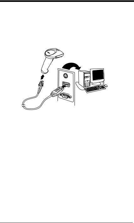
Connecting the Imager When Powered by Host (Keyboard Wedge)
An imager can be connected between the keyboard and PC as a “keyboard wedge,” plugged into the serial port or connected to a portable data terminal. The following is an example of a keyboard wedge connection:
1.Turn off power to the terminal/computer.
2.Disconnect the keyboard cable from the back of the terminal/computer.
1 - 4 |
3800g/3800gHD/3800gPDF User’s Guide |
3.Connect the appropriate interface cable to the imager and to the terminal/ computer.
4. Turn the terminal/computer power back on.
Note: You will not hear a power-up beep because the 3800g is factory defaulted to a USB connection. You must scan the IBM PC AT and Compatibles with CR suffix bar code on page 1-5 to enable keyboard wedge ability.
Verify the imager operation by scanning a bar code from the Sample Symbols in the back of this manual. The imager beeps once.
Keyboard Wedge Connection
Scanning the bar code below allows operation of the 3800g as a keyboard wedge interface to an IBM PC AT with a U. S. keyboard.
If you programmed the imager for a different terminal interface and you want to change to an IBM PC AT and compatibles keyboard wedge interface, scan the bar code below.
Note: The following bar code also programs a carriage return (CR) suffix.
IBM PC AT and Compatibles
with CR suffix
3800g/3800gHD/3800gPDF User’s Guide |
1 - 5 |
Laptop Direct Connect
For most laptops, scanning the Laptop Direct Connect bar code allows operation of the imager in parallel with the integral keyboard. The following Laptop Direct Connect bar code selects terminal ID 03, programs a carriage return (CR) suffix and turns on Emulate External Keyboard (page 2-5).
Laptop Direct Connect
with CR suffix
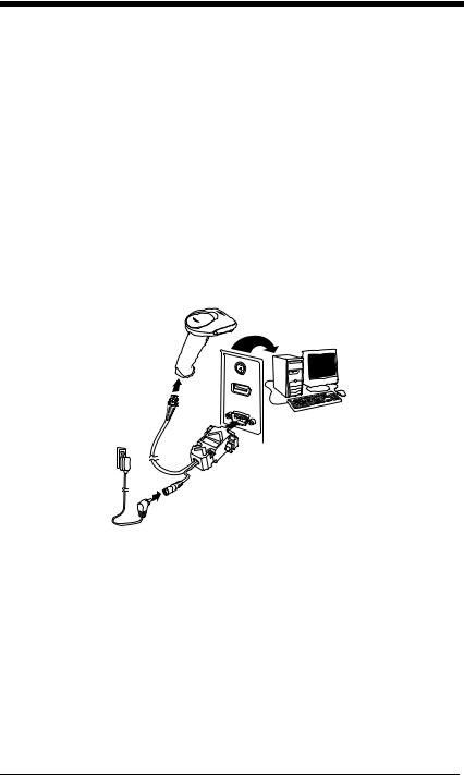
Connecting the Imager with RS-232 Serial Port
1.Turn off power to the terminal/computer.
2.Connect the appropriate interface cable to the imager.
Note: For the imager to work properly, you must have the correct cable for your type of terminal/computer.
3.Plug the serial connector into the serial port on your computer. Tighten the two screws to secure the connector to the port.
4.Connect the power supply and plug into an outlet.
5.Turn the terminal/computer power back on.
Note: You will not hear a power-up beep because the 3800g is factory defaulted to a USB connection. You must scan the RS-232 Interface bar code below to enable RS-232 ability.
1 - 6 |
3800g/3800gHD/3800gPDF User’s Guide |

All communication parameters between the imager and terminal must match for correct data transfer through the serial port using RS-232 protocol. Scanning the RS-232 interface bar code, programs the imager for an RS-232 interface at 38,400 baud, parity–none, 8 data bits, 1 stop bit, and adds a suffix of a CR LF.
RS-232 Interface
Refer to page 2-8 for additional RS-232 configuration settings.
IBM 4683 Ports 5B, 9B, and 17 Interface
Scan one of the following “Plug and Play” codes to program the 3800GX5E for IBM 4683 Port 5B, 9B, or 17.
Note: After scanning one of these codes, you must power cycle the cash register.
IBM 4683 Port 5B Interface
IBM 4683 Port 9B HHBCR-1 Interface
IBM 4683 Port 9B HHBCR-2 Interface
IBM 4683 Port 17 Interface
3800g/3800gHD/3800gPDF User’s Guide |
1 - 7 |
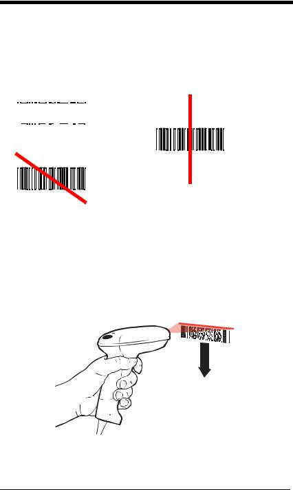
Reading Techniques
The imager has a bright red aiming beam that corresponds to its horizontal field of view. The aiming beam should be centered horizontally over the bar code; it will not read if the aiming beam is in any other direction.
Good Technique |
Bad Technique |
|||||||
|
|
|
|
|
|
|
|
|
|
|
|
|
|
|
|
|
|
|
|
|
|
|
|
|
|
|
|
|
|
|
|
|
|
|
|
Bad Technique
The best focus point for reading most code densities is about 5 inches (12.7 cm) from the unit. To read a single bar code or multiple bar codes (on a page or on an object), hold the imager at an appropriate distance from the target, pull the trigger, and center the aiming beam on the bar code.
Reading PDF417 Bar Codes
Note: Applies to 3800gHD and 3800gPDF.
To read PDF417 bar codes with a PDF-enabled 3800gHD/3800gPDF, hold the trigger down and move the scanner up and down so the aiming line sweeps from the top of the bar code to the bottom, and back up. This ensures that the entire code is scanned.
1 - 8 |
3800g/3800gHD/3800gPDF User’s Guide |

Resetting the Standard Product Defaults
If you aren’t sure what programming options are in your imager, or you’ve changed some options and want the factory settings restored, scan the Standard Product Default Settings bar code below.
Standard Product Default Settings
The Menu Commands starting on page 11-5 lists the factory default settings for each of the commands (indicated by an asterisk (*) on the programming pages).
3800g/3800gHD/3800gPDF User’s Guide |
1 - 9 |

1 - 10 |
3800g/3800gHD/3800gPDF User’s Guide |

2
Terminal Interfaces
Terminal ID
If your interface is not a standard PC AT, refer to Terminal ID, beginning on page 2-1 and locate the Terminal ID number for your PC. Scan the Terminal ID bar code below, then scan the numeric bar code(s) from the Programming Chart inside the back cover of this manual to program the imager for your terminal ID. Scan Save to save your selection.
For example, an IBM AT terminal has a Terminal ID of 003. You would scan the Terminal ID bar code, then 0, 0, 3 from the Programming Chart inside the back cover of this manual, then Save. If you make an error while scanning the digits (before scanning Save), scan the Discard code on the Programming Chart, scan the Terminal ID bar code, scan the digits, and the Save code again.
Terminal ID
Save
Note: After scanning one of these codes, you must power cycle your computer.
3800g/3800gHD/3800gPDF User’s Guide |
2 - 1 |

Supported Terminals
Terminal |
Model(s) |
Terminal ID |
DEC |
VT510, 520, 525 (PC style) |
005 |
DEC |
VT510, 520, 525 (DEC style |
104 |
|
LK411) |
|
Esprit |
200, 400 |
005 |
Heath Zenith |
PC, AT |
003 |
HP |
Vectra |
003 |
IBM |
XT |
001 |
IBM |
PS/2 25, 30, 77DX2 |
002 |
IBM |
AT, PS/2 30–286, 50, 55SX, 60, |
003 |
|
70, 70–061, 70–121, 80 |
|
IBM 102 key |
3151, 3161, 3162, 3163, 3191, |
006 |
|
3192, 3194, 3196, 3197, 3471, |
|
|
3472, 3476, 3477 |
|
IBM 122 key |
3191, 3192, 3471, 3472 |
007 |
IBM 122 key |
3196, 3197, 3476, 3477, 3486, |
008 |
|
3482, 3488 |
|
IBM 122 key |
3180 |
024 |
IBM 122 key |
3180 data entry keyboard |
114 |
IBM DOS/V 106 key |
PC & Workstation |
102 |
IBM SurePOS |
USB Handheld Imager |
128 |
IBM SurePOS |
USB Tabletop Imager |
129 |
IBM Thinkpad |
360 CSE, 340, 750 |
097 |
IBM Thinkpad |
|
106 |
IBM Thinkpad |
365, 755CV |
003 |
I/O 122 key |
2676D, 2677C, 2677D |
008 |
ITT |
9271 |
007 |
Lee Data |
IIS |
007 |
NEC |
98XX Series |
103 |
Olivetti |
M19, M200 |
001 |
Olivetti |
M240, M250, M290, M380, |
003 |
|
P500 |
|
RS-232 TTL |
|
000 |
Silicon Graphics |
Indy, Indigoll |
005 |
Telex 88 key |
078, 078A, 79, 80, 191, 196, |
025 |
|
1191,1192, 1471, 1472, 1476, |
|
|
1477, 1483 |
|
Telex 88 key |
Data Entry Keyboard |
112 |
Telex 102 key |
078, 078A, 79, 80, 191, 196, |
045 |
|
1191,1192, 1471, 1472, 1476, |
|
|
1477, 1483 |
|
2 - 2 |
3800g/3800gHD/3800gPDF User’s Guide |

Supported Terminals (Continued)
Terminal |
Model(s) |
Terminal ID |
Telex 122 key |
078, 078A, 79, 80, 191, 196, |
046 |
|
1191,1192, 1471, 1472, 1476, |
|
|
1477, 1482, 1483 |
|
USB PC Keyboard |
|
124 * |
USB Mac Keyboard |
|
125 |
USB Com Port |
|
130 |
USB HIDPOS |
|
131 |
* Factory default setting
3800g/3800gHD/3800gPDF User’s Guide |
2 - 3 |

Keyboard Country
Scan the appropriate country code below to program the keyboard for your country. As a general rule, the following characters are supported, but need special care for countries other than the United States:
@ | $ # { } [ ] = / ‘ \ < > ~
* United States
Belgium
Denmark
Finland
France
Germany/Austria
Great Britain
Italy
Norway
Spain
Switzerland
2 - 4 |
3800g/3800gHD/3800gPDF User’s Guide |
Loading...