


 Loading...
Xenon™ 1900/1902
Area-Imaging Scanner
User’s Guide
™

Disclaimer
Honeywell International Inc. (“HII”) reserves the right to make changes in specifications and other information contained in this document without prior notice, and the reader should in all cases consult HII to determine whether any such changes have been made. The information in this publication does not represent a commitment on the part of HII.
HII shall not be liable for technical or editorial errors or omissions contained herein; nor for incidental or consequential damages resulting from the furnishing, performance, or use of this material.
This document contains proprietary information that is protected by copyright. All rights are reserved. No part of this document may be photocopied, reproduced, or translated into another language without the prior written consent of HII.
© 2010 Honeywell International Inc. All rights reserved.
Other product names or marks mentioned in this document may be trademarks or registered trademarks of other companies and are the property of their respective owners.
Web Address: www.honeywellaidc.com
Microsoft® Windows®, Windows NT®, Windows 2000, Windows ME, Windows XP, and the Windows logo are trademarks or registered trademarks of Microsoft Corporation.
The Bluetooth® word mark and logos are owned by Bluetooth SIG, Inc.
Other product names or marks mentioned in this document may be trademarks or registered trademarks of other companies and are the property of their respective owners.

Product Agency Compliance - Xenon 1900
USA
FCC Part 15 Subpart B Class B
This device complies with part 15 of the FCC Rules. Operation is subject to the following two conditions:
1.This device may not cause harmful interference.
2.This device must accept any interference received, including interference that may cause undesired operation.
This equipment has been tested and found to comply with the limits for a Class B digital device pursuant to part 15 of the FCC Rules. These limits are designed to provide reasonable protection against harmful interference in a residential installation. This equipment generates, uses, and can radiate radio frequency energy and, if not installed and used in accordance with the instructions, may cause harmful interference to radio communications. However, there is no guarantee that interference will not occur in a particular installation. If this equipment does cause harmful interference to radio or television reception, which can be determined by turning the equipment off and on, the user is encouraged to try to correct the interference by one or more of the following measures:
•Reorient or relocate the receiving antenna.
•Increase the separation between the equipment and receiver.
•Connect the equipment into an outlet on a circuit different from that to which the receiver is connected.
•Consult the dealer or an experienced radio or television technician for help.
If necessary, the user should consult the dealer or an experienced radio/ television technician for additional suggestions. The user may find the following booklet helpful: “Something About Interference.” This is available at FCC local regional offices. Honeywell is not responsible for any radio or television interference caused by unauthorized modifications of this equipment or the substitution or attachment of connecting cables and equipment other than those specified by Honeywell. The correction is the responsibility of the user.
Use only shielded data cables with this system.
Caution: Any changes or modifications made to this equipment not expressly approved by Honeywell may void the FCC authorization to operate this equipment.
UL Statement
UL listed: UL60950-1.

Canada
Industry Canada ICES-003
This Class B digital apparatus complies with Canadian ICES-003. Operation is subject to the following conditions:
1.This device may not cause harmful interference.
2.This device must accept any interference received, including interference that may cause undesired operation.
Conformité à la règlementation canadienne
Cet appareil numérique de la Classe A est conforme à la norme NMB-003 du Canada. Son fonctionnement est assujetti aux conditions suivantes :
1.Cet appareil ne doit pas causer de brouillage préjudiciable.
2.Cet appareil doit pouvoir accepter tout brouillage reçu, y compris le brouillage pouvant causer un fonctionnement indésirable.
cUL Statement
cUL listed: CSA C22.2 No.60950-1-03.
Europe
The CE marking indicates compliance to 2004/108/EC EMC Directive with Standards EN55022 CLASS B, EN55024, EN61000-3-2, EN61000-3-3. In addition, complies to 2006/95/EC Low Voltage Directive, when shipped with recommended power supply.
For further information please contact:
Honeywell Imaging & Mobility Europe BV Nijverheidsweg 9-13
5627 BT Eindhoven The Netherlands
Honeywell International Inc. shall not be liable for use of our product with equipment (i.e., power supplies, personal computers, etc.) that is not CE marked and does not comply with the Low Voltage Directive.
Waste Electrical and Electronic Equipment
Information
Honeywell complies with Directive 2002/96/EC OF THE EUROPEAN PARLIAMENT AND OF THE COUNCIL of 27 January 2003 on waste electrical and electronic equipment (WEEE).
This product has required the extraction and use of natural resources for its production. It may contain hazardous substances that could impact health and the environment, if not properly disposed.

In order to avoid the dissemination of those substances in our environment and to diminish the pressure on the natural resources, we encourage you to use the appropriate take-back systems for product disposal. Those systems will reuse or recycle most of the materials of the product you are disposing in a sound way.
 The crossed out wheeled bin symbol informs you that the product should not be disposed of along with municipal waste and invites you to use the appropriate separate take-back systems for product disposal.
If you need more information on the collection, reuse, and recycling systems, please contact your local or regional waste administration.
You may also contact your supplier for more information on the environmental performances of this product.
Germany
If your product is marked with the GS symbol, then the product has been issued a GS certificate showing compliance to IEC 60950-1.
Australia/NZ
C-Tick Statement
 Conforms to AS/NZS 3548 EMC requirement
Mexico
Conforms to NOM-019.
Russia
Gost-R certificate

South Korea
International
Eye Safety Statement: LED
This device has been tested in accordance with IEC60825-1 LED safety, and has been certified to be a Class 1 LED product.
CB Scheme
Certified to IEC60950-1 (2001) First Edition.
Patents
Please refer to the product packaging for patent information.
Solids and Water Protection
The Xenon 1900 has a rating of IP41, immunity of foreign particles and dripping water.

Product Agency Compliance - Xenon 1902 and
CCB01-010BT Base
USA
FCC Part 15 Subpart C
This device complies with part 15 of the FCC Rules. Operation is subject to the following two conditions:
1.This device may not cause harmful interference.
2.This device must accept any interference received, including interference that may cause undesired operation.
Caution: Any changes or modifications made to this equipment not expressly approved by Honeywell may void the FCC authorization to operate this equipment.
 UL Statement
UL listed: UL60950-1.
Canada
Industry Canada
This device complies with Canadian RSS-210. Operation is subject to the following conditions:
1.This device may not cause interference.
2.This device must accept any interference, including interference that may cause undesired operation.
Conformité à la règlementation canadienne
Cet appareil ISM est conforme à la norme CNR-210 du Canada. Son fonctionnement est assujetti aux conditions suivantes :
1.Cet appareil ne doit pas causer de brouillage préjudiciable.
2.Cet appareil doit pouvoir accepter tout brouillage reçu, y compris le brouillage pouvant causer un fonctionnement indésirable.

 C-UL Statement
C-UL listed: CSA C22.2 No.60950-1-03 for I.T.E product safety.
Europe
The CE marking on the product indicates that this device is in conformity with all essential requirements of the 1999/5/EC R&TTE Directive. In addition, complies to 2006/95/EC Low Voltage Directive, when shipped with recommended power supply. For further information, contact:
Honeywell Imaging & Mobility Europe BV
International Inc.
Nijverheidsweg 9-13
5627 BT Eindhoven
The Netherlands
Honeywell shall not be liable for use of our product with equipment (i.e., power supplies, personal computers, etc.) that is not CE marked and does not comply with the Low Voltage Directive. This equipment is intended for use throughout the European Community and has been assessed to the following standards:
EN 300 328
EN 301 489-1
EN 301 489-17
EN60950-1
EN60825-1
Waste Electrical and Electronic Equipment
Information
Honeywell complies with Directive 2002/96/EC OF THE EUROPEAN PARLIAMENT AND OF THE COUNCIL on waste electrical and electronic equipment (WEEE).
This product has required the extraction and use of natural resources for its production. It may contain hazardous substances that could impact health and the environment, if not properly disposed.
In order to avoid the dissemination of those substances in our environment and to diminish the pressure on the natural resources, we encourage you to use the appropriate take-back systems for product disposal. Those systems will reuse or recycle most of the materials of the product you are disposing in a sound way.
 The crossed out wheeled bin symbol informs you that the product should not be disposed of along with municipal waste and invites you to use the appropriate separate take-back systems for product disposal.

If you need more information on the collection, reuse, and recycling systems, contact your local or regional waste administration.
You may also contact your supplier for more information on the environmental performances of this product.
Germany
If your product is marked with the GS symbol, then the product has been issued a GS certificate showing compliance to IEC 60950-1.
Australia/NZ
C-Tick Statement
 Conforms to AS/NZS 3548 EMC requirements.
Russia
International
Eye Safety Statement
LED
This device has been tested in accordance with IEC60825-1: 1993+A1+A2 LED safety, and has been certified to be a Class 1 LED device.
Radio Technology
Class II
CB Scheme
Certified to CB Scheme IEC 60950-1.

Solids and Water Protection
The Xenon 1902 has a rating of IP41, immunity of foreign particles and dripping water.
Patents
Refer to product packaging for patent information.
Required Safety Labels
Scanner
Illumination output
Item |
Compliance |
Number, Serial |
|
Number and |
Label |
Revision |
location |
Information |
|
location |
|
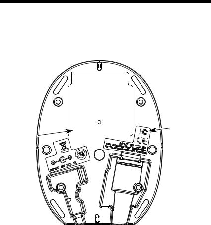
CCB01-010BT Base
Item Number, |
|
Serial |
|
Number and |
Compliance |
Revision |
Label |
Information |
location |
location |
|

Table of Contents
Chapter 1 - Getting Started
About This Manual ...................................................... |
1-1 |
Unpacking Your Device............................................... |
1-1 |
Connecting the Device ................................................ |
1-2 |
Connecting with USB ............................................ |
1-2 |
Connecting with Keyboard Wedge ........................ |
1-3 |
Connecting with RS232 Serial Port ....................... |
1-5 |
Connecting with RS485......................................... |
1-6 |
Reading Techniques ................................................... |
1-8 |
Menu Bar Code Security Settings ............................... |
1-8 |
Setting Custom Defaults ............................................. |
1-9 |
Resetting the Custom Defaults ................................... |
1-9 |
Resetting the Factory Defaults.................................. |
1-10 |
Chapter 2 - Programming the Interface |
|
Introduction ................................................................. |
2-1 |
Programming the Interface - Plug and Play ................ |
2-1 |
Keyboard Wedge................................................... |
2-1 |
Laptop Direct Connect........................................... |
2-1 |
RS232 Serial Port.................................................. |
2-2 |
RS485 ................................................................... |
2-2 |
RS485 Packet Mode ............................................. |
2-3 |
USB IBM SurePos................................................. |
2-4 |
USB PC or Macintosh Keyboard ........................... |
2-4 |
USB HID................................................................ |
2-5 |
USB Serial............................................................. |
2-5 |
Verifone® Ruby Terminal Default Settings ............ |
2-6 |
Gilbarco® Terminal Default Settings ..................... |
2-7 |
Honeywell Bioptic Aux Port Configuration............. |
2-7 |
Datalogic™ Magellan© Bioptic |
|
Aux Port Configuration..................................... |
2-7 |
NCR Bioptic Aux Port Configuration...................... |
2-8 |
Wincor Nixdorf Terminal Default Settings ............. |
2-8 |
i

Wincor Nixdorf Beetle™ Terminal |
|
Default Settings ................................................ |
2-9 |
Keyboard Country Layout .......................................... |
2-10 |
Keyboard Style .......................................................... |
2-17 |
Keyboard Conversion ................................................ |
2-18 |
Control Character Output........................................... |
2-19 |
Keyboard Modifiers.................................................... |
2-19 |
RS232 Baud Rate...................................................... |
2-22 |
RS232 Word Length: Data Bits, Stop Bits, |
|
and Parity ................................................................ |
2-23 |
RS232 Receiver Time-Out......................................... |
2-24 |
RS232 Handshaking.................................................. |
2-24 |
RS232 Timeout.................................................... |
2-25 |
XON/XOFF .......................................................... |
2-25 |
ACK/NAK ............................................................. |
2-25 |
Scanner to Bioptic Communication............................ |
2-26 |
Scanner-Bioptic Packet Mode ............................. |
2-26 |
Scanner-Bioptic ACK/NAK Mode......................... |
2-27 |
Scanner-Bioptic ACK/NAK Timeout..................... |
2-27 |
Chapter 3 - Cordless System Operation |
|
How the Cordless Charge Base/ |
|
Access Point Works .................................................. |
3-1 |
Linking the Scanner to a Charge Base ........................ |
3-1 |
Linking the Scanner to an Access Point ...................... |
3-2 |
Communication Between the Cordless System |
|
and the Host .............................................................. |
3-2 |
RF (Radio Frequency) Module Operation.................... |
3-3 |
System Conditions....................................................... |
3-3 |
Linking Process ..................................................... |
3-3 |
Scanner Is Out of Range ....................................... |
3-4 |
Scanner Is Moved Back Into Range ...................... |
3-4 |
Out of Range and Back into Range |
|
with Batch Mode On ......................................... |
3-4 |
Page Button ................................................................. |
3-4 |
About the Battery ......................................................... |
3-4 |
ii

Charging Information............................................. |
3-5 |
Battery Recommendations .................................... |
3-5 |
Proper Disposal of the Battery .............................. |
3-6 |
Beeper and LED Sequences and Meaning................. |
3-6 |
Scanner LED Sequences and Meaning ................ |
3-7 |
Base/Access Point LED Sequences |
|
and Meaning .................................................... |
3-7 |
Base Power Communication Indicator .................. |
3-8 |
Reset Scanner ............................................................ |
3-8 |
Scanning while in Base Cradle ................................... |
3-8 |
Paging ......................................................................... |
3-9 |
Paging Mode ......................................................... |
3-9 |
Paging Pitch ......................................................... |
3-9 |
Error Indicators............................................................ |
3-9 |
Beeper Pitch - Base Error ..................................... |
3-9 |
Number of Beeps - Base Error ............................ |
3-10 |
Scanner Report ......................................................... |
3-10 |
Scanner Address....................................................... |
3-11 |
Base or Access Point Address.................................. |
3-11 |
Scanner Modes ......................................................... |
3-11 |
Charge Only Mode .............................................. |
3-11 |
Linked Modes ...................................................... |
3-12 |
Unlinking the Scanner ............................................... |
3-13 |
Override Locked Scanner.................................... |
3-13 |
Out-of-Range Alarm .................................................. |
3-13 |
Alarm Sound Type............................................... |
3-14 |
Flexible Power Management..................................... |
3-15 |
Batch Mode ............................................................... |
3-16 |
Batch Mode Beep................................................ |
3-17 |
Batch Mode Storage............................................ |
3-17 |
Batch Mode Quantity........................................... |
3-18 |
Batch Mode Output Order ................................... |
3-20 |
Delete Last Code................................................. |
3-20 |
Clear All Codes ................................................... |
3-20 |
Transmit Records to Host.................................... |
3-21 |
Batch Mode Transmit Delay ................................ |
3-21 |
Multiple Scanner Operation....................................... |
3-21 |
iii

Scanner Name........................................................... |
3-22 |
Application Work Groups ........................................... |
3-24 |
Application Work Group Selection ....................... |
3-25 |
Resetting the Factory Defaults: |
|
All Application Work Groups.................................... |
3-25 |
Resetting the Custom Defaults: |
|
All Application Work Groups.................................... |
3-26 |
Using the Scanner with Bluetooth Devices................ |
3-26 |
PCs/Laptops ........................................................ |
3-26 |
PDAs/Mobility Systems Devices.......................... |
3-27 |
Changing the Scanner’s Bluetooth PIN Code...... |
3-27 |
Minimizing Bluetooth/ISM Band Network Activity ...... |
3-27 |
Auto Reconnect Mode ......................................... |
3-28 |
Maximum Link Attempts ...................................... |
3-29 |
Relink Time-Out................................................... |
3-30 |
Bluetooth/ISM Network Activity Examples........... |
3-30 |
Host Command Acknowledgment ............................. |
3-31 |
Chapter 4 - Input/Output Settings |
|
Power Up Beeper ........................................................ |
4-1 |
Beep on BEL Character............................................... |
4-1 |
Trigger Click................................................................. |
4-2 |
Good Read and Error Indicators.................................. |
4-2 |
Beeper – Good Read............................................. |
4-2 |
Beeper Volume – Good Read................................ |
4-3 |
Beeper Pitch – Good Read.................................... |
4-3 |
Beeper Pitch – Error .............................................. |
4-4 |
Beeper Duration – Good Read .............................. |
4-4 |
LED – Good Read ................................................. |
4-4 |
Number of Beeps – Good Read ............................ |
4-5 |
Number of Beeps – Error....................................... |
4-5 |
Good Read Delay .................................................. |
4-6 |
User-Specified Good Read Delay.......................... |
4-6 |
Manual/Serial Trigger Modes....................................... |
4-6 |
Manual Trigger....................................................... |
4-6 |
Serial Trigger ......................................................... |
4-7 |
iv

Presentation Mode ...................................................... |
4-9 |
Presentation LED Behavior after Decode ............. |
4-9 |
Presentation Sensitivity ......................................... |
4-9 |
In-Stand Sensor Mode .............................................. |
4-10 |
Streaming Presentation™ Mode ............................... |
4-10 |
Streaming Presentation In-Stand Programming.. 4-11 |
|
Mobile Phone Read Mode......................................... |
4-11 |
Image Snap and Ship................................................ |
4-12 |
Hands Free Time-Out ............................................... |
4-12 |
Reread Delay ............................................................ |
4-12 |
User-Specified Reread Delay.................................... |
4-13 |
Illumination Lights ..................................................... |
4-13 |
Aimer Delay............................................................... |
4-14 |
User-Specified Aimer Delay ................................ |
4-14 |
Scanner Time-Out..................................................... |
4-14 |
Aimer Mode............................................................... |
4-15 |
Centering................................................................... |
4-15 |
Preferred Symbology ................................................ |
4-17 |
High Priority Symbology ...................................... |
4-17 |
Low Priority Symbology....................................... |
4-18 |
Preferred Symbology Time-out ........................... |
4-18 |
Preferred Symbology Default .............................. |
4-18 |
Output Sequence Overview ...................................... |
4-19 |
Require Output Sequence................................... |
4-19 |
Output Sequence Editor ...................................... |
4-19 |
To Add an Output Sequence............................... |
4-19 |
Other Programming Selections ........................... |
4-20 |
Output Sequence Editor ...................................... |
4-21 |
Partial Sequence ................................................. |
4-21 |
Require Output Sequence................................... |
4-22 |
Multiple Symbols ....................................................... |
4-22 |
No Read .................................................................... |
4-23 |
Video Reverse........................................................... |
4-24 |
Chapter 5 - Data Editing
Prefix/Suffix Overview ................................................. |
5-1 |
v

To Add a Prefix or Suffix:....................................... |
5-1 |
To Clear One or All Prefixes or Suffixes ................ |
5-2 |
To Add a Carriage Return Suffix |
|
to All Symbologies............................................ |
5-3 |
Prefix Selections .......................................................... |
5-3 |
Suffix Selections .......................................................... |
5-4 |
Function Code Transmit .............................................. |
5-4 |
Intercharacter, Interfunction, |
|
and Intermessage Delays.......................................... |
5-4 |
Intercharacter Delay .............................................. |
5-5 |
User Specified Intercharacter Delay ...................... |
5-5 |
Interfunction Delay................................................. |
5-6 |
Intermessage Delay............................................... |
5-6 |
Chapter 6 - Data Formatting |
|
Data Format Editor Introduction................................... |
6-1 |
To Add a Data Format ................................................. |
6-1 |
Other Programming Selections.............................. |
6-3 |
Terminal ID Table ........................................................ |
6-4 |
Data Format Editor Commands ................................... |
6-4 |
Move Commands................................................... |
6-5 |
Search Commands ................................................ |
6-6 |
Miscellaneous Commands..................................... |
6-7 |
Data Formatter............................................................. |
6-8 |
Data Format Non-Match Error Tone ...................... |
6-9 |
Primary/Alternate Data Formats ................................ |
6-10 |
Single Scan Data Format Change ....................... |
6-10 |
Chapter 7 - Symbologies |
|
All Symbologies ........................................................... |
7-2 |
Message Length Description ....................................... |
7-2 |
Codabar ....................................................................... |
7-3 |
Codabar Concatenation......................................... |
7-4 |
Code 39 ....................................................................... |
7-6 |
Code 32 Pharmaceutical (PARAF) ........................ |
7-8 |
Full ASCII............................................................... |
7-9 |
vi

Code 39 Code Page.............................................. |
7-9 |
Interleaved 2 of 5 ...................................................... |
7-10 |
NEC 2 of 5................................................................. |
7-12 |
Code 93..................................................................... |
7-14 |
Code 93 Code Page............................................ |
7-14 |
Straight 2 of 5 Industrial (three-bar start/stop) .......... |
7-15 |
Straight 2 of 5 IATA (two-bar start/stop).................... |
7-16 |
Matrix 2 of 5 .............................................................. |
7-17 |
Code 11..................................................................... |
7-18 |
Code 128................................................................... |
7-19 |
ISBT 128 Concatenation ..................................... |
7-19 |
Code 128 Code Page.......................................... |
7-20 |
GS1-128.................................................................... |
7-21 |
Telepen ..................................................................... |
7-22 |
UPC-A ....................................................................... |
7-23 |
UPC-A/EAN-13 |
|
with Extended Coupon Code .................................. |
7-25 |
UPC-E0 ..................................................................... |
7-26 |
UPC-E1 ..................................................................... |
7-29 |
EAN/JAN-13.............................................................. |
7-29 |
ISBN Translate .................................................... |
7-31 |
EAN/JAN-8................................................................ |
7-32 |
MSI............................................................................ |
7-34 |
GS1 DataBar Omnidirectional................................... |
7-36 |
GS1 DataBar Limited ................................................ |
7-36 |
GS1 DataBar Expanded............................................ |
7-37 |
Trioptic Code............................................................. |
7-38 |
Codablock A.............................................................. |
7-38 |
Codablock F .............................................................. |
7-40 |
PDF417 ..................................................................... |
7-41 |
MicroPDF417 ............................................................ |
7-42 |
GS1 Composite Codes ............................................. |
7-43 |
UPC/EAN Version ............................................... |
7-43 |
GS1 Emulation .......................................................... |
7-44 |
TCIF Linked Code 39 (TLC39).................................. |
7-45 |
QR Code ................................................................... |
7-45 |
Data Matrix................................................................ |
7-47 |
vii

MaxiCode................................................................... |
7-48 |
Aztec Code ................................................................ |
7-49 |
Chinese Sensible (Han Xin) Code ............................. |
7-50 |
Postal Codes - 2D...................................................... |
7-51 |
Single 2D Postal Codes:...................................... |
7-51 |
Combination 2D Postal Codes:............................ |
7-52 |
Postal Codes - Linear ................................................ |
7-54 |
China Post (Hong Kong 2 of 5)............................ |
7-54 |
Korea Post ........................................................... |
7-56 |
Chapter 8 - Imaging Commands |
|
Single-Use Basis ......................................................... |
8-1 |
Command Syntax ........................................................ |
8-1 |
Image Snap - IMGSNP ................................................ |
8-2 |
IMGSNP Modifiers ................................................. |
8-2 |
Image Ship - IMGSHP ................................................. |
8-5 |
IMGSHP Modifiers ................................................. |
8-5 |
Intelligent Signature Capture - IMGBOX.................... |
8-14 |
Signature Capture Optimize ................................ |
8-14 |
IMGBOX Modifiers............................................... |
8-15 |
RF Default Imaging Device........................................ |
8-19 |
Chapter 9 - Interface Keys |
|
Keyboard Function Relationships ................................ |
9-1 |
Supported Interface Keys ............................................ |
9-3 |
Chapter 10 - Utilities |
|
To Add a Test Code I.D. Prefix to All Symbologies ... |
10-1 |
Show Decoder Revision ............................................ |
10-1 |
Show Scan Driver Revision ....................................... |
10-1 |
Show Software Revision............................................ |
10-1 |
Show Data Format..................................................... |
10-2 |
Test Menu.................................................................. |
10-2 |
TotalFreedom ............................................................ |
10-2 |
Application Plug-Ins (Apps) ....................................... |
10-3 |
viii
EZConfig Introduction ............................................... |
10-3 |
Installing EZConfig from the Web........................ |
10-4 |
Chapter 11 - Serial Programming Commands |
|
Conventions .............................................................. |
11-1 |
Menu Command Syntax............................................ |
11-1 |
Query Commands ..................................................... |
11-2 |
Responses .......................................................... |
11-3 |
Trigger Commands ................................................... |
11-4 |
Resetting the Custom Defaults ................................. |
11-4 |
Menu Commands...................................................... |
11-5 |
Chapter 12 - Product Specifications |
|
1900 Scanner Product Specifications ....................... |
12-1 |
1902 Scanner Product Specifications ....................... |
12-2 |
CCB01-010BT Charge Base |
|
Product Specifications ............................................ |
12-3 |
Standard Cable Pinouts ............................................ |
12-4 |
Keyboard Wedge................................................. |
12-4 |
Serial Output ...................................................... |
12-5 |
RS485 Output ..................................................... |
12-6 |
USB ..................................................................... |
12-7 |
Chapter 13 - Maintenance |
|
Repairs...................................................................... |
13-1 |
Maintenance.............................................................. |
13-1 |
Cleaning the Device ............................................ |
13-1 |
Inspecting Cords and Connectors ....................... |
13-1 |
Replacing Cables in Corded Scanners ..................... |
13-1 |
Replacing an Interface Cable .............................. |
13-2 |
Replacing Cables and Batteries |
|
in Cordless Systems ............................................... |
13-2 |
Replacing an Interface Cable in a Base .............. |
13-2 |
Changing a scanner Battery................................ |
13-3 |
Troubleshooting a Xenon Scanner............................ |
13-3 |
ix

Troubleshooting a Cordless System.......................... |
13-4 |
Troubleshooting a Base....................................... |
13-4 |
Troubleshooting a Cordless Scanner .................. |
13-5 |
Chapter 14 - Customer Support |
|
Appendix A - Reference Charts |
|
Symbology Chart ........................................................ |
A-1 |
ASCII Conversion Chart (Code Page 1252) ............... |
A-4 |
Code Page Mapping of Printed Barcodes .................. |
A-6 |
x

1
Getting Started
About This Manual
This User’s Guide provides installation and programming instructions for the Xenon™ 1900 and 1902 area-imaging scanners. Product specifications, dimensions, warranty, and customer support information are also included.
Honeywell bar code scanners are factory programmed for the most common terminal and communications settings. If you need to change these settings, programming is accomplished by scanning the bar codes in this guide.
An asterisk (*) next to an option indicates the default setting.
Unpacking Your Device
After you open the shipping carton containing the product, take the following steps:
•Check for damage during shipment. Report damage immediately to the carrier who delivered the carton.
•Make sure the items in the carton match your order.
•Save the shipping container for later storage or shipping.
1 - 1
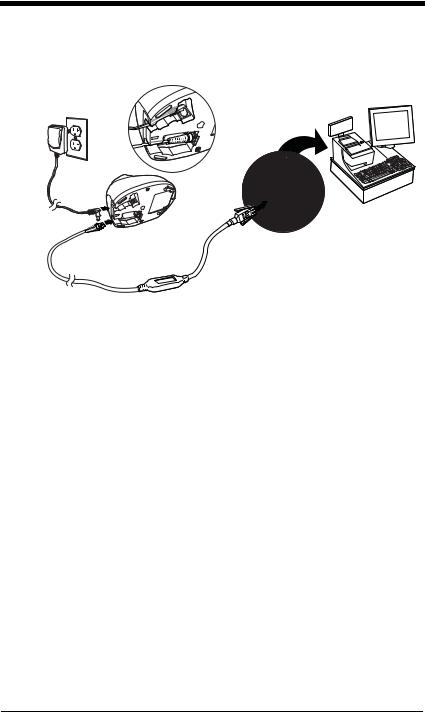
Connecting the Device
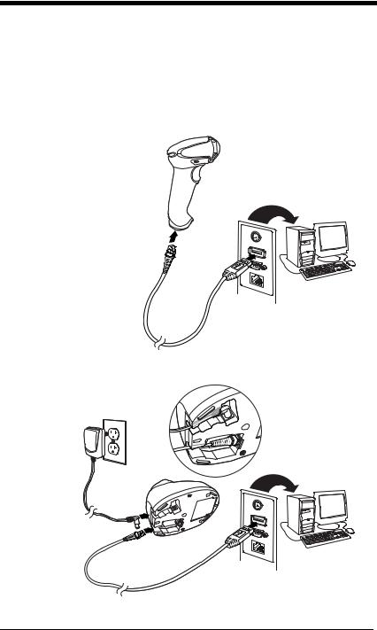
Connecting with USB
A scanner or a cordless base can be connected to the USB port of a computer.
1.Connect the appropriate interface cable to the device first, then to the computer.
Corded Scanner USB
Connection:
Cordless Base USB
Connection:
1 - 2
2.Make sure the cables are secured in the wireways in the bottom of the cordless base and that the base sits flat on a horizontal surface.
3.The scanner beeps.
4.Verify the scanner or cordless base operation by scanning a bar code from the Sample Symbols in the back of this manual.
The unit defaults to a USB PC Keyboard. Refer to page 2-4 for other USB terminal settings.
For additional USB programming and technical information, refer to “USB Application Note,” available at www.honeywellaidc.com.
Connecting with Keyboard Wedge
A scanner or cordless base can be connected between the keyboard and PC as a “keyboard wedge,” plugged into the serial port, or connected to a portable data terminal in wand emulation or non decoded output mode.
The following is an example of a keyboard wedge connection:
1.Turn off power and disconnect the keyboard cable from the back of the terminal/computer.
2.Connect the appropriate interface cable to the device and to the terminal/computer.
Corded Scanner Keyboard Wedge Connection:
1 - 3

Cordless Base
Keyboard Wedge
Connection:
3.Make sure the cables are secured in the wireways in the bottom of the cordless base and that the base sits flat on a horizontal surface.
4.Turn the terminal/computer power back on. The scanner beeps.
5.Verify the scanner or cordless base operation by scanning a bar code from the Sample Symbols in the back of this manual. The scanner beeps once.
The unit defaults to an IBM PC AT and compatibles keyboard wedge interface with a USA keyboard. A carriage return (CR) suffix is added to bar code data.
1 - 4

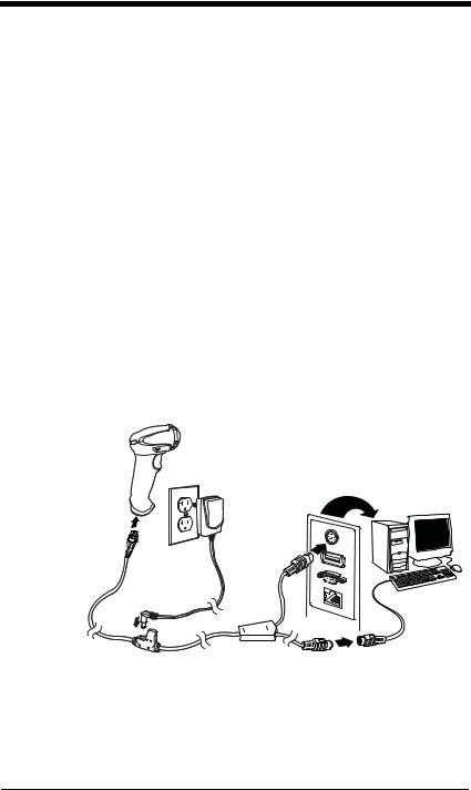
Connecting with RS232 Serial Port
1.Turn off power to the terminal/computer.
2.Connect the appropriate interface cable to the scanner.
Note: For the scanner or cordless base to work properly, you must have the correct cable for your type of terminal/computer.
Corded Scanner
RS232 Serial Port
Connection:
Cordless Base
RS232 Serial Port
Connection:
1 - 5
3.Make sure the cables are secured in the wireways in the bottom of the cordless base and that the base sits flat on a horizontal surface.
4.Plug the serial connector into the serial port on your computer. Tighten the two screws to secure the connector to the port.
5.Once the scanner or cordless base has been fully connected, power up the computer.
This interface programs 115,200 baud, 8 data bits, no parity, and 1 stop bit.
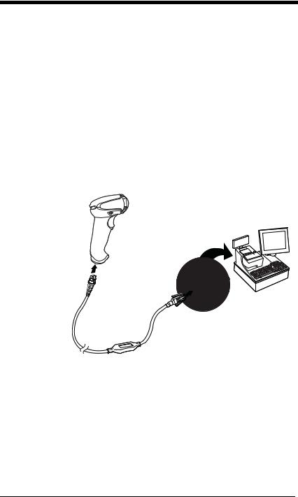
Connecting with RS485
A scanner or cordless base can be connected for an IBM POS terminal interface.
1.Connect the appropriate interface cable to the device, then to the computer.
Corded Scanner
RS485
Connection:
1 - 6
Cordless Base
RS485
Connection:
2.Make sure the cables are secured in the wireways in the bottom of the cordless base and that the base sits flat on a horizontal surface.
3.Turn the terminal/computer power back on. The scanner beeps.
4.Verify the scanner or cordless base operation by scanning a bar code from the Sample Symbols in the back of this manual. The scanner beeps once.
For further RS485 settings, refer to RS485, page 2-2..
1 - 7
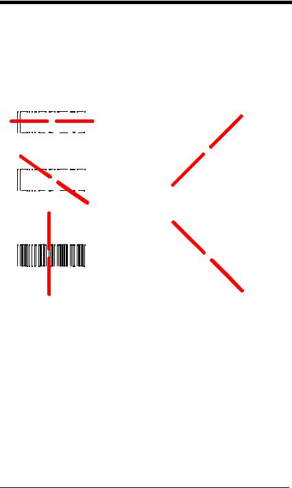
Reading Techniques
The scanner has a view finder that projects a bright red aiming beam that corresponds to the scanner’s horizontal field of view. The aiming beam should be centered over the bar code, but it can be positioned in any direction for a good read.
Linear bar code |
2D Matrix symbol |
|||||||||||||||||||||
|
|
|
|
|
|
|
|
|
|
|
|
|
|
|
|
|
|
|
|
|
|
|
|
|
|
|
|
|
|
|
|
|
|
|
|
|
|
|
|
|
|
|
|
|
|
|
|
|
|
|
|
|
|
|
|
|
|
|
|
|
|
|
|
|
|
|
|
|
|
|
|
|
|
|
|
|
|
|
|
|
|
|
|
|
|
|
|
|
|
|
|
|
|
|
|
|
|
|
|
|
|
|
|
|
|
|
|
|
|
|
|
|
|
|
The aiming beam is smaller when the scanner is closer to the code and larger when it is farther from the code. Symbologies with smaller bars or elements (mil size) should be read closer to the unit. Symbologies with larger bars or elements (mil size) should be read farther from the unit. To read single or multiple symbols (on a page or on an object), hold the scanner at an appropriate distance from the target, pull the trigger, and center the aiming beam on the symbol. If the code being scanned is highly reflective (e.g., laminated), it may be necessary to tilt the code up 15° to 18° to prevent unwanted reflection.
Menu Bar Code Security Settings
Honeywell scanners are programmed by scanning menu bar codes or by sending serial commands to the scanner. If you want to restrict the ability to scan menu codes, you can use the Menu Bar Code Security settings. Please contact the nearest technical support office (see Technical Assistance on page 14-1) for further information.
1 - 8
Loading...