


OPERATOR’S MANUAL
MANUEL D’UTILISATION
MANUAL DEL OPERADOR
ELECTRIC LOG SPLITTER
FENDEUSE DE BÛCHES ÉLECTRIQUE
PARTIDORA DE TRONCOS ELÉCTRICA
UT49103
Your log splitter has been engineered and manufactured to our high standard for dependability, ease of operation, and operator safety. When properly cared for, it will give you years of rugged, trouble-free performance.
 WARNING: To reduce the risk of injury, the user must read and understand the operator’s manual before using this product.
Thank you for your purchase.
SAVE THIS MANUAL FOR FUTURE REFERENCE
Ce fendeuse de bûches a été conçu et fabriqué conformément à nos strictes normes de fiabilité, simplicité d’emploi et sécurité d’utilisation. Correctement entretenu, cet outil vous donnera des années de fonctionnement robuste et sans problème.
 AVERTISSEMENT : Pour réduire les risques de blessures, l’utilisateur doit lire et veiller à bien comprendre le manuel d’utilisation avant d’employer ce produit.
Merci de votre achat.
Su partidora de troncos ha sido diseñado y fabricado de conformidad con nuestras estrictas normas para brindar fiabilidad, facilidad de uso y seguridad para el operador. Con el debido cuidado, le brindará muchos años de sólido funcionamiento y sin problemas.
 ADVERTENCIA: Para reducir el riesgo de lesiones, el usuario debe leer y comprender el manual del operador antes de usar este producto.
Le agradecemos su compra.
CONSERVER CE MANUEL POUR |
GUARDE ESTE MANUAL PARA |
FUTURE RÉFÉRENCE |
FUTURAS CONSULTAS |
See this fold-out section for all the figures referenced in the operator’s manual.
Voir que cette section d’encart pour toutes les figures a adressé dans le manuel d’utilisation.
Vea esta sección de la página desplegable para todas las figuras mencionó en el manual del operador.
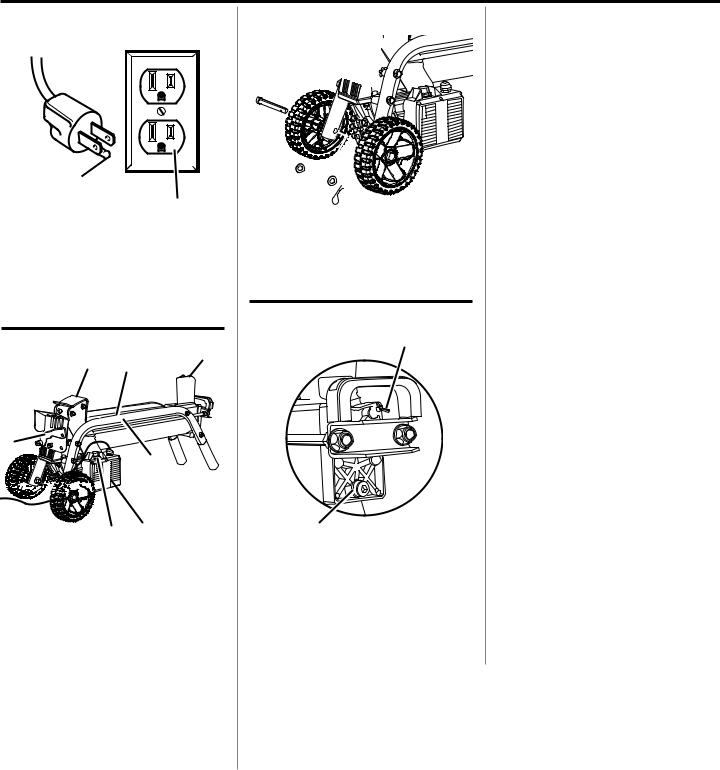
Fig. 1
A
B
A - Grounding pin (broche de mise à la terre, patilla de conexión a tierra)
B - Cover of grounded outlet box (couvercle du boîtier de raccordement, cubierta de la caja de la toma de corriente con conexión a tierra)
Fig. 2
B C D
A
E


 F H G
F H G
A - Hydraulic control lever (levier de commande hydraulique, palanca de control hidráulico)
B - RAM (vérin, ariete)
C - Work table (gâchette, gatillo del interruptor) D - Wedge (coin, cuña)
E - Side supports (supports latéraux, soportes laterales)
F - Reset / overload button (bouton de réinitialisation / surcharge , botón de reajuste / sobrecarga)
G - Push button box (boîtier de commande, caja de botones pulsadores)
H - On/off switch - (interrupteur marche/arrêt, interruptor de encendido/apagado)
Fig. 3
A
B
C
A - Axle (essieu, eje)
B - Washer (rondelle, arandela)
C - Hitch pin (axe d’attelage, pasador del enganche
Fig. 4
A
B
A - Bleed screw (vis de purge, tornillo de purga)
B - Oil drain bolt with dipstick (boulon de vidange d’huile et jauge, perno de drenaje de aceite con varilla para medir el nivel del aceite)
Fig. 5
A
B
A - Dipstick (jauge, varilla para medir el nivel de aceite)
B - Oil lines (repères, conductors de aceite)
Fig. 6
A B
A - Hydraulic control lever (levier de commande hydraulique, palanca de control hidráulico)
B - On/off switch - (interrupteur marche/arrêt, interruptor de encendido/apagado)
ii
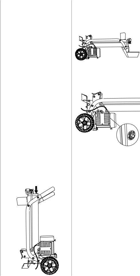
Fig. 7
Fig. 8
RIGHT
(CORRECT, FORMA CORRECTA)
Fig. 9
WRONG
(MAL, INCORRECTO)
Fig. 10
RIGHT
(CORRECT, FORMA CORRECTA)
A
A - Wood wedge (coin de bois, cuña de madera)
Fig. 11 |
WRONG |
|
|
|
(MAL, INCORRECTO) |
A
A - Wood wedge (coin de bois, cuña de madera)
Fig. 12
POSITION IN WHICH TO CHECK OIL LEVEL
(POSITION POUR LA VÉRIFICATION DU
NIVEAU D’HUILE)
(POSICIÓN CORRECTA PARA REVISAR EL
NIVEL DE ACEITE)
Fig. 13
DRAINING OIL FROM OIL TANK
(VIDANGER DE L’HUILE DU
RÉSERVOIR HYDRAULIQUE)
(OPERACIÓN DE DRENADO DEL ACEITE)
Fig. 14
RESET BUTTON
(BOUTON « RESET »)
(BOTÓN DE REAJUSTE)
Fig. 15
A
A - Padlock (cadenas, candado)
iii

TABLE OF CONTENTS
TABLE DES MATIÈRES / ÍNDICE DE CONTENIDO
Introduction....................................................................................................................................................................... |
2 |
Introduction / Introducción |
|
General Safety Rules...................................................................................................................................................... |
3-4 |
Règles de sécurité générales / Reglas de seguridad generales |
|
Specific Safety Rules........................................................................................................................................................ |
5 |
Règles de sécurité particulières / Reglas de seguridad específicas |
|
Symbols............................................................................................................................................................................ |
6 |
Symboles / Símbolos |
|
Electrical............................................................................................................................................................................ |
7 |
Caractéristiques électriques / Aspectos eléctricos |
|
Features............................................................................................................................................................................ |
8 |
Caractéristiques / Características |
|
Assembly........................................................................................................................................................................ |
8-9 |
Assemblage / Armado |
|
Operation..................................................................................................................................................................... |
9-10 |
Utilisation / Funcionamiento |
|
Maintenance.................................................................................................................................................................... |
11 |
Entretien / Mantenimiento |
|
Troubleshooting............................................................................................................................................................... |
12 |
Dépannage / Solución de problemas |
|
Warranty.......................................................................................................................................................................... |
13 |
Garantie / Garantía |
|
Parts Ordering and Service................................................................................................................................ |
Back Page |
Commande de pièces et réparation / Pedidos de piezas y servicio.......................................................... |
Page arrière / Pág. posterior |
INTRODUCTION
INTRODUCTION / INTRODUCCIÓN
This product has many features for making its use more pleasant and enjoyable. Safety, performance, and dependability have been given top priority in the design of this product making it easy to maintain and operate.
* * *
Ce produit offre de nombreuses fonctions destinées à rendre son utilisation plus plaisante et satisfaisante. Lors de la conception de ce produit, l’accent a été mis sur la sécurité, les performances et la fiabilité, afin d’en faire un outil facile à utiliser et à entretenir.
* * *
Este producto ofrece numerosas características para hacer más agradable y placentero su uso. En el diseño de este producto se ha conferido prioridad a la seguridad, el desempeño y la fiabilidad, por lo cual se facilita su manejo y mantenimiento.
2 — English

GENERAL SAFETY RULES
WARNING:
READ AND UNDERSTAND ALL INSTRUCTIONS. Failure to follow all instructions listed below, may result in electric shock, fire and/or serious personal injury.
READ ALL INSTRUCTIONS
KNOW YOUR POWER TOOL. Read the operator’s manual carefully. Learn the applications and limitations as well as the specific potential hazards related to this tool.
GUARD AGAINST ELECTRICAL SHOCK BY PREVENTING BODY CONTACT WITH GROUNDED SURFACES. For example: pipes, radiators, ranges, refrigerator enclosures.
KEEP GUARDS IN PLACE and in good working order.
REMOVE ADJUSTING KEYS AND WRENCHES. Form habit of checking to see that keys and adjusting wrenches are removed from tool before turning it on.
KEEPWORKAREACLEAN.Clutteredareasandbenches invite accidents. DO NOT leave tools or pieces of wood on the tool while it is in operation.
DO NOT USE IN DANGEROUS ENVIRONMENTS. Do not use power tools in damp or wet locations or expose to rain. Keep the work area well lit.
KEEP CHILDREN AND BYSTANDERS AWAY. All bystanders should wear safety glasses and be kept a safe distance from work area. Do not let bystanders contact tool or extension cord while operating.
MAKE WORKSHOP CHILDPROOF with padlocks, master switches, or by removing starter keys.
DON’T FORCE THE TOOL. It will do the job better and safer at the feed rate for which it was designed.
USE THE RIGHT TOOL. Do not force the tool or attachment to do a job for which it was not designed.
USE THE PROPER EXTENSION CORD. Make sure your extension cord is in good condition. Use only a cord heavy enough to carry the current your product will draw. An undersized cord will cause a drop in line voltage resulting in loss of power and overheating. A wire gauge size (A.W.G.) of at least 14 is recommended for an extension cord 25 feet or less in length. If in doubt, use the next heavier gauge.Thesmallerthegaugenumber,theheavierthecord.
DRESS PROPERLY. Do not wear loose clothing, neckties, or jewelry that can get caught and draw you into moving parts. Rubber gloves and nonskid footwear are recommended when working outdoors. Also wear protectivehaircoveringtocontainlonghairaboveshoulder length.
ALWAYS WEAR SAFETY GLASSES WITH SIDE SHIELDS. Everyday eyeglasses have only impactresistant lenses, they are NOT safety glasses.
SECURE WORK. Use clamps or a vise to hold work when practical, it is safer than using your hand and frees both hands to operate the tool.
DO NOT OVERREACH. Keep proper footing and balance at all times.
MAINTAIN TOOLS WITH CARE. Keep tools sharp and clean for better and safer performance. Follow instructions for lubricating and changing accessories.
DISCONNECTTOOLS.When not in use, before servicing, or when changing attachments, blades, bits, cutters, etc., all tools should be disconnected from power source.
AVOID ACCIDENTAL STARTING. Be sure switch is off when plugging in any tool.
USE RECOMMENDED ACCESSORIES. Consult the operator’s manual for recommended accessories. The use of improper accessories may result in injury.
NEVER STAND ON TOOL. Serious injury could occur if the tool is tipped.
CHECK DAMAGED PARTS. Before further use of the tool, a guard or other part that is damaged should be carefully checked to determine that it will operate properly and perform its intended function. Check for alignment of moving parts, binding of moving parts, breakage of parts, mounting and any other conditions that may affect its operation. A guard or other part that is damaged must be properly repaired or replaced by an authorized service center to avoid risk of personal injury.
USE THE RIGHT DIRECTION OF FEED. Feed work into a blade, cutter, or sanding spindle against the direction or rotation of the blade, cutter, or sanding spindle only.
NEVER LEAVE TOOL RUNNING UNATTENDED. TURN THE POWER OFF. Don’t leave tool until it comes to a complete stop.
PROTECT YOUR LUNGS. Wear a face or dust mask if the cutting operation is dusty.
PROTECT YOUR HEARING. Wear hearing protection during extended periods of operation.
DO NOT ABUSE CORD. Never carry tool by the cord or yank it to disconnect from receptacle. Keep cord from heat, oil, and sharp edges.
USE OUTDOOR EXTENSION CORDS. When tool is used outdoors, use only extension cords with approved ground connection that are intended for use outdoors and so marked.
NEVER USE IN AN EXPLOSIVE ATMOSPHERE.
Normal sparking of the motor could ignite fumes.
INSPECT TOOL CORDS PERIODICALLY. If damaged, have repaired by a qualified service technician at an authorized service facility. The conductor with insulation having an outer surface that is green with or without yellow stripes is the equipment-grounding conductor. If repair or replacement of the electric cord or plug is necessary,
3 — English

GENERAL SAFETY RULES
do not connect the equipment-grounding conductor to a live terminal. Repair or replace a damaged or worn cord immediately. Stay constantly aware of cord location and keep it well away from the rotating blade.
INSPECT EXTENSION CORDS PERIODICALLY and replace if damaged.
KEEP TOOL DRY, CLEAN, AND FREE FROM OIL AND GREASE. Always use a clean cloth when cleaning. Never use brake fluids, gasoline, petroleum-based products, or any solvents to clean tool.
STAY ALERT AND EXERCISE CONTROL. Watch what you are doing and use common sense. Do not operate tool when you are tired. Do not rush.
DO NOT USE TOOL IF SWITCH DOES NOT TURN IT ON AND OFF. Have defective switches replaced by an authorized service center.
DO NOT OPERATE A TOOL WHILE UNDER THE INFLUENCE OF DRUGS, ALCOHOL, OR ANY MEDICATION.
ALWAYS carry the tool only by the carrying handle.
USE ONLY RECOMMENDED ACCESSORIES listed in this manual or addendums. Use of accessories that are not listed may cause the risk of personal injury. Instructions for safe use of accessories are included with the accessory.
TOOL SERVICE MUST BE PERFORMED ONLY BY QUALIFIED REPAIR PERSONNEL.
Service or maintenance performed by unqualified
personal could result in a risk of injury.
WHEN SERVICING use only identical replacement parts. Use of any other parts may create a hazard or cause product damage.
ALWAYS STAY ALERT! Do not allow familiarity (gained from frequent use of your tool) to cause a careless mistake. ALWAYS REMEMBER that a careless fraction of a second is sufficient to inflict severe injury.
MAKESURETHE WORK AREA HASAMPLE LIGHTING to see the work and that no obstructions will interfere with safe operation BEFORE performing any work using your tool.
ALWAYS TURN OFF THE TOOL before disconnecting it to avoid accidental starting when reconnecting to power supply. NEVERleave the tool unattended while connected to a power source.
4 — English

SPECIFIC SAFETY RULES
DO NOT ALLOW anyone to operate the log splitter who has not read the operator’s manual or has not been instructed on the safe use of the splitter.
NEVER ALLOW CHILDREN OR UNTRAINED ADULTS TO OPERATE THIS MACHINE.
IF SOMEONE is helping load logs to be split, DO NOT start the machine until that person is clear of the area.
NEVER ALLOW ANYONE TO RIDE ON THE MACHINE.
NEVER TRANSPORT ANYTHING OR ANYONE ON THE LOG SPLITTER.
HIGH FLUID PRESSURES ARE DEVELOPED IN HYDRAULIC LOG SPLITTERS. Pressurized hydraulic fluid escaping through a pin hole opening can puncture skin and cause severe blood poisoning. Heed the following instructions at all times:
a)Do not operate the machine with frayed, kinked, cracked, or damaged hoses, fittings, or tubing.
b)Stop the engine and relieve hydraulic system pressure before changing or adjusting fittings, hoses, tubing, or other system components.
c)Donotadjustthepressuresettingsofthepumporvalue.
d)Never use your hand. Leaks can be located by passing cardboard or wood over the suspected area. Look for discoloration. If injured by escaping fluid, see a doctor at once. Serious infection or reaction can develop if proper medical treatment is not administered immediately.
KEEP THE OPERATOR ZONE and adjacent area clear for safe, secure footing.
LOG SPLITTERS SHOULD BE USED ONLY for splitting wood. DO NOT use for other purposes unless the manufacturer provides attachments and instructions.
MAKE SURE THE LOG SPLITTER is on a level surface. Block the splitter as required to prevent unintended movement.
ALWAYS OPERATE the splitter from the manufacturer’s indicated operator zone.
LOGS TO BE SPLIT ON RAM-TYPE UNITS should be cut as squarely as possible.
THE MACHINE OWNER should instruct anyone assisting him or her in safe log splitting operation.
ALWAYS operate the log splitter with all safety equipment in place and all controls properly adjusted for safe operation.
ALWAYS operate the log splitter at manufacturer’s recommended speed.
WHENLOADING a ram-type log splitter, place your hands on the sides of the log not at the ends. NEVER place your hands or any part of your body between a log and any part of the log splitter.
ON RAM-TYPE log splitters, NEVER attempt to split more than one (1) log at a time unless the ram has been fully extended and a second log is needed to complete the separation of the first log.
ON RAM-TYPE log splitters on which the logs are not square, the longest portion of the log should be rotated down and the most square end placed against the ram.
CLEAR DEBRIS from moving parts but only when the power source is shut off.
USE ONLY YOUR HAND TO OPERATE THE LOG SPLITTER CONTROLS.
ALWAYS UNPLUG FROM THE POWER SOURCE while repairing or adjusting the splitter except as recommended by the manufacturer.
CIRCUIT CAPACITY AND FUSES:
a)Use only an electrical circuit having adequate capacity as recommended by the log splitter manufacturer.
b)“Blowing” a fuse or tripping a circuit breaker is usually a warning that you are overloading the machine or have too many devices taking power from the circuit, or both. Do not install a higher capacity fuse!
LEARN AND UNDERSTAND all controls and the proper use of the equipment.
SAVE THESE INSTRUCTIONS. Refer to them frequently and use to instruct other users. If you loan someone this tool, loan them these instructions also.
5 — English
SYMBOLS
The following signal words and meanings are intended to explain the levels of risk associated with this product.
SYMBOL |
SIGNAL |
MEANING |
|
|
|
|
DANGER: |
Indicates an imminently hazardous situation, which, if not avoided, will result |
|
in death or serious injury. |
|
|
|
|
|
|
|
|
WARNING: |
Indicates a potentially hazardous situation, which, if not avoided, could result |
|
in death or serious injury. |
|
|
|
|
|
|
|
|
CAUTION: |
Indicates a potentially hazardous situation, which, if not avoided, may result in |
|
minor or moderate injury. |
|
|
|
|
|
|
|
|
CAUTION: |
(Without Safety Alert Symbol) Indicates a situation that may result in property |
|
damage. |
|
|
|
Some of the following symbols may be used on this tool. Please study them and learn their meaning. Proper interpretation of these symbols will allow you to operate the tool better and safer.
SYMBOL |
NAME |
DESIGNATION/EXPLANATION |
|
Safety Alert |
Indicates a potential personal injury hazard. |
|
Read Operator’s Manual |
To reduce the risk of injury, user must read and understand operator’s |
|
manual before using this product. |
|
|
|
|
|
Eye Protection |
Always wear eye protection marked to comply with ANSI Z87.1. |
|
Wet Conditions Alert |
Do not expose to rain or use in damp locations. |
|
Wear Gloves |
Always wear nonslip, heavy-duty protective gloves when |
|
operating this product. |
|
|
|
|
|
Wear Safety Footwear |
Always wear nonslip safety footwear when operating this product. |
10' 3m |
Keep Bystanders Away |
Always keep bystanders at least 10 ft. (3 m) away. |
|
Keep Hands Away |
Always keep hands away from the wedge and the ram. |
V |
Volts |
Voltage |
A |
Amperes |
Current |
Hz |
Hertz |
Frequency (cycles per second) |
|
Alternating Current |
Type of current |
|
Class II Construction |
Double-insulated construction |
|
|
6 — English |

ELECTRICAL
EXTENSION CORDS
Use only 3-wire extension cords that have 3-prong grounding plugs and 3-pole receptacles that accept the tool's plug. When using a power tool at a considerable distance from the power source, use an extension cord heavy enough to carry the current that the tool will draw. An undersized extension cord will cause a drop in line voltage, resulting in a loss of power and causing the motor to overheat. Use the chart provided below to determine the minimum wire size required in an extension cord. Only round jacketed cords listed by Underwriter's Laboratories (UL) should be used.
**Ampere rating (on tool faceplate) |
|
|
|
|
||
|
0-2.0 |
2.1-3.4 |
3.5-5.0 5.1-7.0 |
7.1-12.0 |
12.1-16.0 |
|
|
|
|
|
|||
Cord Length |
Wire Size (A.W.G.) |
|
|
|||
|
|
|
|
|
|
|
25' |
16 |
16 |
16 |
16 |
14 |
14 |
|
|
|
|
|
|
|
50' |
16 |
16 |
16 |
14 |
14 |
12 |
|
|
|
|
|
|
|
100' |
16 |
16 |
14 |
12 |
10 |
— |
|
|
|
|
|
|
|
**Used on 12 gauge - 20 amp circuit.
NOTE: AWG = American Wire Gauge
When working with the tool outdoors, use an extension cord that is designed for outside use. This is indicated by the letters “WA” or “W” on the cord's jacket.
Before using an extension cord, inspect it for loose or exposed wires and cut or worn insulation.
WARNING:
Keep the extension cord clear of the working area. Position the cord so that it will not get caught on lumber, tools or other obstructions while you are working with a power tool. Failure to do so can result in serious personal injury.
 WARNING:
Check extension cords before each use. If damaged replace immediately. Never use tool with a damaged cord since touching the damaged area could cause electrical shock resulting in serious injury.
ELECTRICAL CONNECTION
This tool is powered by a precision built electric motor. It should be connected to a power supply that is 120 volts, 60 Hz, AC only (normal household current). Do not operate this tool on direct current (DC). A substantial voltage drop will cause a loss of power and the motor will overheat. If the product does not operate when plugged into an outlet, double check the power supply.
SPEED AND WIRING
The speed is not constant and decreases under a load or with lower voltage. For voltage, the wiring in a shop is as important as the motor’s horsepower rating. A line intended only for lights cannot properly carry a power tool motor. Wire that is heavy enough for a short distance will be too light for a greater distance. A line that can support one power tool may not be able to support two or three tools.
GROUNDING INSTRUCTIONS
In the event of a malfunction or breakdown, grounding provides a path of least resistance for electric current to reduce the risk of electric shock. This tool is equipped with an electric cord having an equipment-grounding conductor and a grounding plug. The plug must be plugged into a matching outlet that is properly installed and grounded in accordance with all local codes and ordinances.
Do not modify the plug provided. If it will not fit the outlet, have the proper outlet installed by a qualified electrician. Improper connection of the equipment-grounding conductor can result in a risk of electric shock. The conductor with insulation having an outer surface that is green with or without yellow stripes is the equipment-grounding conductor. If repair or replacement of the electric cord or plug is necessary, do not connect the equipment-grounding conductor to a live terminal.
Check with a qualified electrician or service personnel if the grounding instructions are not completely understood, or if in doubt as to whether the tool is properly grounded.
Repair or replace a damaged or worn cord immediately.
This tool is intended for use on a circuit that has an outlet like the one shown in figure 1. It also has a grounding pin like the one shown.
7 — English

FEATURES
PRODUCT SPECIFICATIONS
Hydraulic Cylinder Pressure |
.................................. 2320 psi |
|
Oil Capacity |
................................................... |
3.4 qts. (3.2 l) |
Input............................ |
120 Volt, 60 Hz, AC Only, 15 Amps |
|
Log Capacity Diameter, maximum |
............................. 12 in. |
Log Capacity Diameter, minimum................................ |
4 in. |
Log Capacity Length............................................... |
20.5 in. |
KNOW YOUR LOG SPLITTER
See Figure 2.
Before attempting to use this product, familiarize yourself with all operating features and safety rules.
BLEED SCREW
Loosen the bleed screw to ensure the smooth flow of air in and out of the oil tank.
HYDRAULIC CONTROL LEVER
Push down on the hydraulic control lever and the ram starts pushing the log into the wedge.
LIFT HANDLE
The lift handle makes rolling the log splitter from one location to another simple and easy.
RESET/OVERLOAD BUTTON
If the motor is overloaded the machine will shut off. Remove the load and push the reset/overload button to restart the machine.
OIL DRAIN BOLT WITH DIPSTICK
Oil drain bolt with dipstick makes checking and changing hydraulic oil easy.
SIDE SUPPORTS
Side supports on each side of the work table keep logs resting securely on the log splitter.
WORK TABLE
Provides surface to support log prior to splitting operation.
ASSEMBLY
UNPACKING
This product has been shipped completely assembled.
nCarefully remove the tool and any accessories from the box. Make sure that all items listed in the packing list are included.
 WARNING:
Do not use this product if any parts on the Packing List are already assembled to your product when you unpack it. Parts on this list are not assembled to the product by the manufacturer and require customer installation. Use of a product that may have been improperly assembled could result in serious personal injury.
nInspect the tool carefully to make sure no breakage or damage occurred during shipping.
nDo not discard the packing material until you have carefully inspected and satisfactorily operated the tool.
nIf any parts are damaged or missing, please call 1-800-242-4672 for assistance.
 WARNING:
If any parts are damaged or missing do not operate this product until the parts are replaced. Use of this product with damaged or missing parts could result in serious personal injury.
 WARNING:
Do not attempt to modify this tool or create accessories not recommended for use with this tool. Any such alteration or modification is misuse and could result in a hazardous condition leading to possible serious personal injury.
 WARNING:
Do not connect to power supply until assembly is complete. Failure to comply could result in accidental starting and possible serious personal injury.
PACKING LIST
Log Splitter
Wheel (2)
Hardware Bag
Operator’s Manual
CAUTION:
Failure to loosen the bleed screw prior to operation of this product may cause the seals in the hydraulic system to blow out. Blown seals could cause permanent damage to the log splitter.
8 — English
ASSEMBLY
ASSEMBLING THE WHEELS
See Figure 3.
To attach the wheels to the base:
nLocate the axle assembly; remove the hitch pin from the axle.
nLift the machine slightly and slip the axle into the wheel hole.
nNext, slide the washer onto the axle. Still lifting the machine, slide the axle/wheel/washer combination into
the wheel mounting hole in the machine base as shown in figure 3.
nSlide the washer onto the axle. Push the hitch pin into the hole on the end of the axle to secure the wheel assembly.
NOTE: The hitch pin should be pushed into the axle until the center of the pin rests on top of the axle.
nRepeat with the second wheel assembly.
OPERATION
 WARNING:
Do not allow familiarity with tools to make you careless. Remember that a careless fraction of a second is sufficient to inflict serious injury.
 WARNING:
Always wear eye protection with side shields marked to comply with ANSI Z87.1. Failure to do so could result in objects being thrown into your eyes, resulting in possible serious injury.
WARNING:
Do not use any attachments or accessories not recommended by the manufacturer of this tool. The use of attachments or accessories not recommended can result in serious personal injury.
BEFORE USING THE LOG SPLITTER
See Figures 4 - 5.
Never operate the log splitter until the bleed screw has been slightly loosened (one to two full turns). Air flow through the bleed screw should be detectable once the log splitter is started. If no air flow is detected, loosen the screw until the air flow can be felt.
Air must flow in and out of the oil tank during operation to prevent the seals in the hydraulic system from rupturing.
This tool is designed for home use only. Never split logs larger than 12 in. diameter or 20-1/2 in. long. Some types of wood are harder to split than others. If the log splitter is having trouble splitting a log, never continue to try for longer than five seconds.
Always check the oil level before you start the log splitter.
To check the oil level:
nUnplug the log splitter.
nUsing the lift handle, stand the log splitter on the end with the wheels (see figure 12).
nUsing an 8 mm hex key, remove the oil drain bolt and wipe the dipstick clean.
nWipe the dipstick clean then reinsert it back into the oil tank.
nRemove the dipstick and check to see if the oil level is between the first and second groove on the dipstick.
nIf there is not enough oil in the oil tank, add oil until the proper level is reached.
nIf there is the proper amount of oil in the oil tank, wipe the dipstick clean then replace it in the oil tank and tighten the oil drain bolt securely.
NOTE: See Replacing Hydraulic Oil in the Maintenance section for recommended oil or equivalents.
9 — English

OPERATION
STARTING THE LOG SPLITTER
See Figures 6 - 7.
nOperator should be positioned at the rear of the log splitter as shown in figure 7.
nPlace the left hand on the hydraulic control lever and the right hand on the on/off switch.
nPush down and hold the on/off switch.
nWhile continuing to hold down the on/off switch, push down and hold the hydraulic control lever.
NOTE: Both hands are required to start this product. The combination of both steps starts the ram which pushes the log into the wedge.
nTo stop the splitter, release both controls to return the ram to the starting position.
NOTE: If only one hand is removed from either the switch or the lever, the log splitter will freeze in place. When both the switch and the lever are released, the ram will return to the starting position.
SPLITTING LOGS
See Figures 8 - 9.
Always place logs lengthwise on the work table and resting firmly on the side supports with one end against the wedge. Place logs flat and in the direction of the grain. Never angle the log to split it or place the log crosswise on the splitter. Never split more than one log at a time.
CAUTION:
Never keep pressure on the wood by trying to force the log splitter for more than five seconds. After five seconds, the oil will heat and can damage the tool.
nPlace log lengthwise and lying flat on the work table.
NOTE: If the log is small, place it against the wedge before starting the splitter.
nUsing the right hand, push down and hold the on/off switch.
nPush down and hold the hydraulic control lever with the left hand. With both the lever and the on/off switch activated, the ram will push the log into the wedge and split the wood.
nOnce the log is split, release both controls to return the ram to the starting position.
FREEING A JAMMED LOG
See Figures 10 - 11.
nRelease both controls.
nInsert a wood wedge under the jammed log after the ram is back at the starting position, .
nStart the log splitter to push the wood wedge completely under the jammed log.
nIf the log is still jammed, repeat the above steps as needed using a thicker angled wood wedge until the log is completely freed.
WARNING:
Never try to knock the jammed log off the splitter. Doing so may damage the tool or may cause the log to fly up and hit someone causing injury.
10 — English
 Loading...