


OPERATOR’S
MANUAL
Manuel d’utilisation
Manual del operador
electric pressure washer
NETTOYEUR PRESSION À électrique Lavadora de presión A ELÉCTRICA
HL80220
To register your Homelite product, please visit: http://register.homelite.com/
Pour enregistrer votre produit de
Homelite, s’il vous plaît la visite:
http://register.homelite.com/
Para registrar su producto de
Homelite, por favor visita:
http://register.homelite.com/
Your pressure washer has been engineered and manufactured to our high standard for dependability, ease of operation, and operator safety. When properly cared for, it will give you years of rugged, trouble-free performance.
 WARNING: To reduce the risk of injury, the user must read and understand the operator’s manual before using this product.
Thank you for your purchase.
SAVE THIS MANUAL FOR FUTURE REFERENCE
Ce nettoyeur pression a été conçu et fabriqué conformément aux strictes normes de fiabilité, simplicité d’emploi et sécurité d’utilisation. Correctement entretenu, il vous donnera des années de fonctionnement robuste et sans problème.
 AVERTISSEMENT : Pour réduire les risques de blessures, l’utilisateur doit lire et veiller à bien comprendre le manuel d’utilisation avant d’utiliser ce produit.
Merci de votre achat.
Su lavadora de presión ha sido diseñada y fabricada de conformidad con las estrictas normas para brindar fiabilidad, facilidad de uso y seguridad para el operador. Con el debido cuidado, le brindará muchos años de sólido y eficiente funcionamiento.
 ADVERTENCIA:Para reducir el riesgo de lesiones, el usuario debe leer y comprender el manual del operador antes de usar este producto.
Le agradecemos su compra.
CONSERVER CE MANUEL POUR |
|
GUARDE ESTE MANUAL PARA |
FUTURE RÉFÉRENCE |
|
FUTURAS CONSULTAS |
|
|
|
See this fold-out section for all of the figures referenced in the operator’s manual.
Consulter l’encart à volets afin d’examiner toutes les figures mentionnées dans le manuel d’utilisation.
Consulte esta sección desplegable para ver todas las figuras a las que se hace referencia en el manual del operador.
ii

Fig. 1
Fig. 2 |
b |
 A
A
A - Test button (bouton de test, botón de prueba)
B- Reset button (bouton de réinitialisation, botón de reajuste)
Fig. 4
C
D
 B
B
A
A - Hitch pin (goupille de sûreté, pasador del enganche)
B - Washer (rondelle, arandela) C - Wheel (roue, rueda)
D - Axle (essieu, eje)
f
Fig. 3
|
e |
|
G |
c |
H |
I
b
 J
J

 A
A
d
A - On/off switch (commutateur marche / arrêt, interruptor de encendido)
B - Nozzle storage (rangement de buses, almacenamiento para boquilla)
C - Spray wand (lance de pulvérisation, tubo de rociado)
D - Detergent tank (réservoir de détergent, tanque de detergente)
E - Hydrosurge/detergent lever (levier « Hydrosurge/détergent », palanca de Hydrosurge/detergente)
F- High pressure trigger lock-out (dispositif de verrouillage de la gâchette à haute pression, seguro de gatillo de alt a presión)
G- High pressure trigger (gâchette à haute pression, gatillo de alt a presión)
H- Hose (tuyau, manguera)
I- Telescoping handle (poignée télescopique, mango telescópico)
J- Power cord storage (rangement de cordon d’alimentation, almacenamiento para cordón de corriente)
K- G-Clean Detergent Injector (injecteur de détergent, inyector de detergente)
Fig. 5
A 
C
 D
D
B
A - Handle assembly (ensemble de poignée, conjunto del mango)
B - Button (bouton, botón) C - Collar (colier, casquilo) D - Label (étiquette, etiqueta)
Fig. 6
A
B
“Click”
«Déclic »
“Clic”
A - Spray wand end (extrémité de la lance d’arrosage, extremo del tubo rociador)
B - Locking collar (bague de blocage, collar de ajuste)
iii

Fig. 7
A
D
B C
A - High pressure hose (tuyau de haute pression, manguera de alt a presión)
B - Low pressure hose (tuyau de basse pression, manguera de la presión baja)
C - Latch (loquet, broche)
D - Hose lock (verrouillage de tuyau, seguro de la manguera)
Fig. 8
b
A 


A - Bracket (support, placa)
B - G-Clean detergent injector (injecteur de détergent, inyector de detergente )
Fig. 9
b
A
A - Garden hose (tuyau d’arrosage, manguera de jardín)
B - G-Clean detergent injector (injecteur de détergent, inyector de detergente )
Fig. 10
A
A - Water intake coupler (coupleur de rise d’eau, acoplador de entrada de agua)
Fig. 11 A
A - On/off switch (commutateur marche / arrêt, interruptor de encendido)
Fig. 12
A
A - Detergent dial (cadran de détergent, esfera de detergente)
Fig. 13
B
A
A - Cap (capuchon, tapa)
B - G-Clean detergent pouch (poche de détergent G-Clean, biolsa de detergente G-Clean)
iv
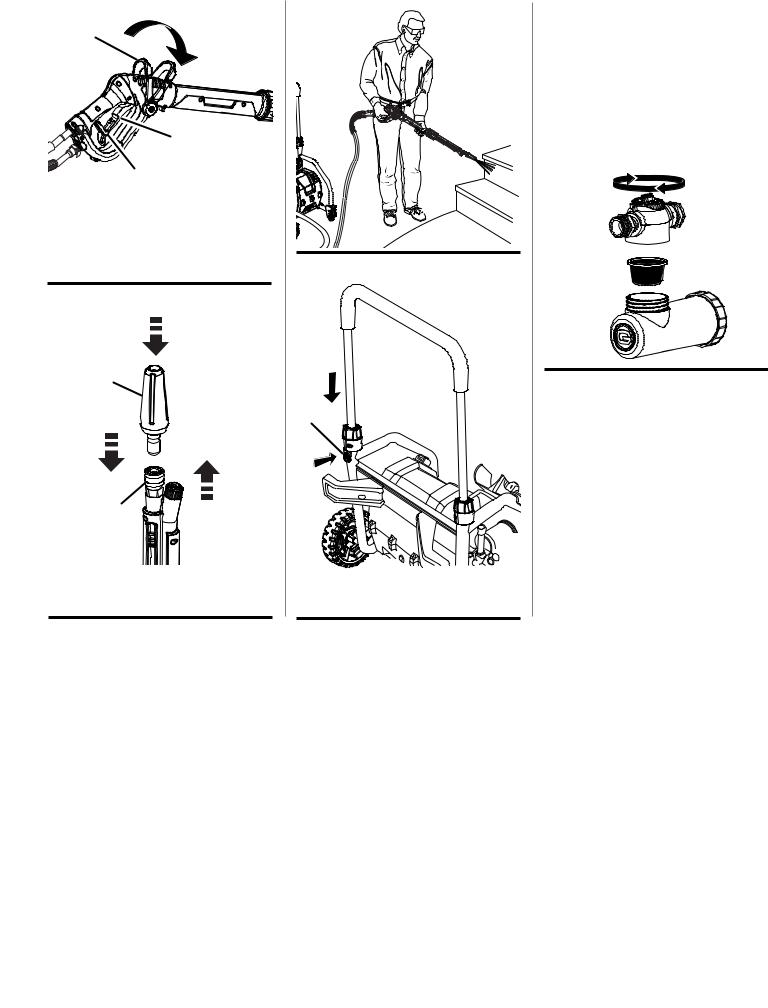
Fig. 14
A
B
C
A - Hydrosurge/low pressure (high flow) lever (pression Hydrosurge/faible, palanca de presión baja [alto flujo]/ Hydrosurge)
B - High pressure trigger (gâchette à haute pression, gatillo de alt a presión)
C - Lock-out (verrouillage, seguro)
Fig. 15
A
B
A - Turbo nozzle (buse turbo, boquilla turbo)
B - Quick connect collar (collier à ressort, collar de conexión rápido)
Fig. 16
Fig. 17
A
A- Handle release button (bouton de dégagement de la poignée, botón de liberación del mango)
Fig. 18
unscrew injector head, then lift and remove to access the screen for cleaning
DÉVISSER LA TÊTE DE L’INJECTEUR, PUIS LE SOULEVER POUR ACCÉDER AU TAMIS AFIN DE LE NETTOYER
DESENROSQUE EL CABEZAL DEL INYECTOR, LUEGO LEVANTE Y RETIRE LA REJILLA PARA LIMPIARLA
v

TABLE OF CONTENTS |
|
TABLE DES MATIÈRES / ÍNDICE DE CONTENIDO |
|
Introduction....................................................................................................................................................................... |
2 |
Introduction / Introducción |
|
Important Safety Instructions............................................................................................................................................ |
3 |
Instructions importantes concernant la sécurité / Instrucciones de seguridad importantes |
|
Specific Safety Rules..................................................................................................................................................... |
4-5 |
Règles de sécurité particulières / Reglas de seguridad específicas |
|
Symbols......................................................................................................................................................................... |
6-7 |
Symboles / Símbolos |
|
Electrical............................................................................................................................................................................ |
8 |
Caractéristiques électriques / Aspectos eléctricos |
|
Features............................................................................................................................................................................ |
9 |
Caractéristiques / Características |
|
Assembly...................................................................................................................................................................... |
9-10 |
Assemblage / Armado |
|
Operation................................................................................................................................................................... |
11-13 |
Utilisation / Funcionamiento |
|
Maintenance.................................................................................................................................................................... |
13 |
Entretien / Mantenimiento |
|
Troubleshooting............................................................................................................................................................... |
14 |
Recherche de pannes / Solución de problemas |
|
Warranty.......................................................................................................................................................................... |
15 |
Garantie / Garantía |
|
Parts Ordering and Service................................................................................................................................ |
Back Page |
Commande de pièces et réparation / Pedidos de piezas y servicio.......................................................... |
Page arrière / Pág. posterior |
introduction |
|
Introduction / Introducción |
|
This product has many features for making its use more pleasant and enjoyable. Safety, performance, and dependability have been given top priority in the design of this product making it easy to maintain and operate.
* * *
Ce produit offre de nombreuses fonctions destinées à rendre son utilisation plus plaisante et satisfaisante. Lors de la conception de ce produit, l’accent a été mis sur la sécurité, les performances et la fiabilité, afin d’en faire un outil facile à utiliser et à entretenir.
* * *
Este producto ofrece numerosas características para hacer más agradable y placentero su uso. En el diseño de este producto se ha conferido prioridad a la seguridad, el desempeño y la fiabilidad, por lo cual se facilita su manejo y mantenimiento.
Page 2

important safety instructions
WARNING:
Read and understand all instructions. Failure to follow all instructions listed below may result in electric shock, fire, and/or serious personal injury.
WARNING:
When using this product basic precautions should always be followed, including the following:
READ ALL INSTRUCTIONS BEFORE USING THIS PRODUCT
To reduce the risk of injury, close supervision is necessary when a product is used near children.
Be thoroughly familiar with controls. Know how to stop the product and release pressure quickly.
Stay alert and exercise control. Watch what you are doing and use common sense. Do not operate product when you are tired. Do not rush.
Do not operate the product while under the influence of drugs, alcohol, or any medication.
Keep the area of operation clear of all persons, particularly small children, and pets.
Don’t overreach or stand on unstable support. Keep proper footing and balance at all times.
Follow the maintenance instructions specified in this manual.
This product is provided with a ground fault circuit interrupter built into the power cord plug. If replacement of the plug or cord is needed, use only identical replacement parts.
WARNING: Risk of injection or injury – Do not direct discharge stream at persons.
This Product Shall Only Be Connected To a Power Supply Receptacle Protected
By A Ground Fault Circuit Interrupter.
SAVE THESE INSTRUCTIONS
ground fault circuit interrupter protection
This pressure washer is provided with a ground fault circuit interrupter (GFCI) built into the plug of the power supply cord. This device provides additional protection from the risk of electric shock. Should replacement of the plug or cord become necessary, use only identical replacement parts that include GFCI protection.
servicing of a double-insulated appliance
In a double-insulated product, two systems of insulation are provided instead of grounding. No grounding means is provided on a double-insulated product, nor should a means for grounding be added to the product. Servicing a doubleinsulated product requires extreme care and knowledge of the system, and should be done only by qualified service personnel. Replacement parts for a double insulated product must be identical to the parts they replace. A doubleinsulated product is marked with the words “DOUBLE INSULATION” or “DOUBLE INSULATED.” The symbol 


 may also be marked on the product.
extension cords
Use only extension cords that are intended for outdoor use. These extension cords are identified by a marking “Acceptable for use with outdoor appliances; store indoors while not in use.” Use only extension cords having an electrical rating not less than the rating of the product. Do not use damaged extension cords. Examine extension cord before using and replace if damaged. Do not abuse extension cord and do not yank on any cord to disconnect. Keep cord away from heat and sharp edges. Always disconnect the extension cord from the receptacle before disconnecting the product from the extension cord.
WARNING: To reduce the risk of electrocution, keep all connections dry and off the ground. Do not touch plug with wet hands.
Page 3 — English

SPECIFIC SAFETY RULES
Know your product. Read the operator’s manual carefully. Learn the machine’s applications and limitations as well as the specific potential hazards related to this product.
To reduce the risk of injury, keep children and visitors away. All visitors should wear safety glasses and be kept a safe distance from work area.
Use right product. Don’t force product or attachment to do a job it was not designed for. Don’t use it for a purpose not intended.
Dress properly. Do not wear loose clothing, gloves, neckties, or jewelry. They can get caught and draw you into moving parts. Rubber gloves and nonskid footwear are recommended when working outdoors. Also wear protective hair covering to contain long hair.
Do not operate the equipment while barefoot or when wearing sandals or similar lightweight footwear. Wear protective footwear that will protect your feet and improve your footing on slippery surfaces.
Exercise caution to avoid slipping or falling.
Alwayswear eye protection with side shields marked to comply with ANSI Z87.1. Following this rule will reduce the risk of serious personal injury.
Use only recommended accessories. The use of improper accessories may cause risk of injury.
Check damaged parts. Before further use of the product, a guard or other part that is damaged should be carefully checked to determine that it will operate properly and perform its intended function. Check for alignment of moving parts, binding of moving parts, breakage of parts, mounting, and any other conditions that may affect its operation. A guard or other part that is damaged must be properly repaired or replaced by an authorized service center to avoid risk of personal injury.
Never leave product running unattended. Turn power off. Don’t leave product until it comes to a complete stop.
Keep the motor free of grass, leaves, or grease to reduce the chance of a fire hazard.
Follow manufacturer’s recommendations for safe loading, unloading, transport, and storage of machine.
Keep product dry, clean, and free from oil and grease.
Always use a clean cloth when cleaning. Never use brake fluids, gasoline, petroleum-based products, or any solvents to clean product.
Check the work area before each use. Remove all objects such as rocks, broken glass, nails, wire, or string which can be thrown or become entangled in the machine.
Do not use product if switch does not turn it off. Have defective switches replaced by an authorized service center.
Avoid dangerous environment. Don’t expose to rain. Keep work area well lit.
Do not abuse the cord. Never use the cord to carry the product or to disconnect the plug from an outlet. Keep cord away from heat, oil, sharp edges, or moving parts. Replace damaged cords immediately. Damaged cords increase the risk of electric shock.
Ground Fault Circuit Interrupter (GFCI) protection should be provided on the circuit(s) or outlet(s) to be used for the product. Receptacles are available having built-in GFCI protection and may be used for this measure of safety.
To reduce the risk of electric shock, this product has a polarized plug (one blade is wider than the other) and will require the use of a polarized extension cord.
The plug will fit into a polarized extension cord only one way. If the plug does not fit fully into the extension cord, reverse the plug. If the plug still does not fit, obtain a correct polarized extension cord. A polarized extension cord will require the use of a polarized wall outlet. This plug will fit into the polarized wall outlet only one way. If the plug does not fit fully into the wall outlet, reverse the plug. If the plug still does not fit, contact a qualified electrician to install the proper wall outlet. Do not change the equipment plug, extension cord receptacle, or extension cord plug in any way.
Make sure your extension cord is in good condition.
When using an extension cord, be sure to use one heavy enough to carry the current your product will draw. A wire gauge size (A.W.G.) of at least 14 is recommended for an extension cord 25 feet or less in length. If in doubt, use the next heavier gauge. The smaller the gauge number, the heavier the cord. An undersized cord will cause a drop in line voltage resulting in loss of power and overheating.
WARNING: Use outdoor extension cords marked SW-A, SOW-A, STW-A, STOW-A, SJW-A, SJTW-A, or SJTOWA. These cords are rated for outdoor use and reduce the risk of electric shock.
Inspect extension cords periodically and replace if damaged. Keep handles dry, clean, and free from oil or grease.
Never direct a water stream toward people or pets, or any electrical device.
Before starting any cleaning operation, close doors and windows. Clear the area to be cleaned of debris, toys, outdoor furniture, or other objects that could create a hazard.
Page 4 — English

SPECIFIC SAFETY RULES
Do not use acids, alkalines, solvents, flammable material, bleaches, or industrial grade solutions in this product. These products can cause physical injuries to the operator and irreversible damage to the machine.
WARNING: High pressure jets can be dangerous if subjecttomisuse.Thejetmustnotbedirectedatpersons, animals, electrical devices, or the machine itself.
Keep the motor away from flammables and other hazardous materials.
Check bolts and nuts for looseness before each use. A loose bolt or nut may cause serious motor problems.
before storing, allow the motor to cool.
When servicing use only identical replacement parts.
Use of any other parts may create a hazard or cause product damage.
Only use cold water.
Make sure minimum clearance of 3 feet is maintained from combustible materials.
Connect pressure washer only to an individual branch circuit.
Hold the handle and wand securely with both hands.
Expect the trigger handle to move when the trigger is pulled due to reaction forces. Failure to do so could cause loss of control and injury to yourself and others.
Save these instructions. Refer to them frequently and use them to instruct other users. If you loan someone this product, loan them these instructions also.
Page 5 — English
SYMBOLS
The following signal words and meanings are intended to explain the levels of risk associated with this product.
SYMBOL |
SIGNAL |
MEANING |
|
|
|
|
DANGER: |
Indicates an imminently hazardous situation, which, if not avoided, will result |
|
in death or serious injury. |
|
|
|
|
|
|
|
|
WARNING: |
Indicates a potentially hazardous situation, which, if not avoided, could result |
|
in death or serious injury. |
|
|
|
|
|
|
|
|
CAUTION: |
Indicates a potentially hazardous situation, which, if not avoided, may result in |
|
minor or moderate injury. |
|
|
|
|
|
|
|
|
CAUTION: |
(Without Safety Alert Symbol) Indicates a situation that may result in property |
|
damage. |
|
|
|
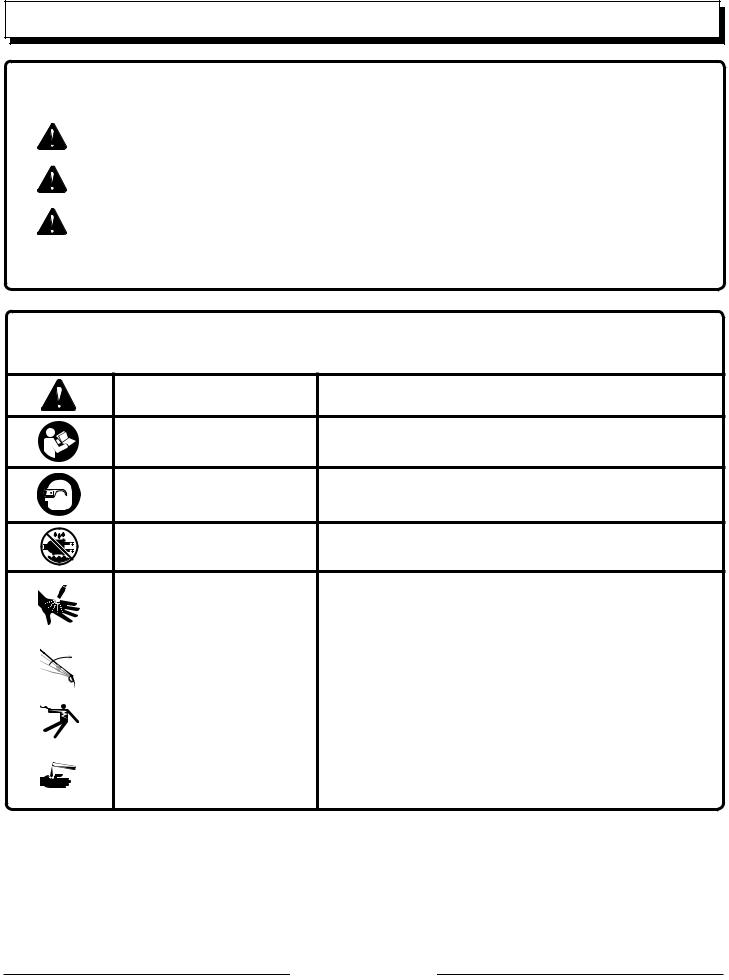
Some of the following symbols may be used on this product. Please study them and learn their meaning. Proper interpretation of these symbols will allow you to operate the product better and safer.
SYMBOL |
NAME |
DESIGNATION/EXPLANATION |
|
Safety Alert |
Indicates a potential personal injury hazard. |
|
Read Operator’s Manual |
To reduce the risk of injury, user must read and understand |
|
operator’s manual before using this product. |
|
|
|
|
|
Eye Protection |
Always wear eye protection with side shields marked to comply |
|
with ANSI Z87.1. |
|
|
|
|
|
Wet Conditions Alert |
Do not expose to rain or use in damp locations. |
|
|
|
To reduce the risk of injection or injury, never direct a water stream |
|
|
|
|
|
|
Risk of Injection |
towards people or pets or place any body part in the stream. Leak- |
|
|
ing hoses and fittings are also capable of causing injection injury. |
|
|
|
|
|
|
|
|
Do not hold hoses or fittings. |
|
|
|
|
|
|
Kickback |
To reduce the risk of injury from kickback, hold the spray wand |
|
|
||
|
|
securely with both hands when the machine is on. |
|
|
|
|
|
|
|
|
|
|
|
|
|
|
|
Electric Shock |
Failure to use in dry conditions and to observe safe practices can |
|
|
||
|
|
result in electric shock. |
|
|
|
|
|
|
|
|
|
|
|
|
|
|
|
|
To reduce the risk of injury or damage, DO NOT USE ACIDS, |
|
|
|
|
|
|
Chemical Burns |
ALKALINES, BLEACHES, SOLVENTS, FLAMMABLE MATERIAL, |
|
|
|
OR INDUSTRIAL GRADE SOLUTIONS in this product. |
|
|
|
Page 6 — English
SYMBOLS
Some of the following symbols may be used on this product. Please study them and learn their meaning. Proper interpretation of these symbols will allow you to operate the product better and safer.
SYMBOL |
NAME |
DESIGNATION/EXPLANATION |
||
|
|
|
|
|
|
V |
Volts |
Voltage |
|
|
|
|
|
|
|
A |
Amperes |
Current |
|
|
|
|
|
|
Hz |
Hertz |
Frequency (cycles per second) |
||
|
|
|
|
|
|
W |
Watt |
Power |
|
|
|
|
|
|
|
|
|
Alternating Current |
Type of current |
|
|
|
|
|
no |
No Load Speed |
Rotational speed, at no load |
||
|
|
|
Class II Construction |
Double-insulated construction |
|
|
|
||
|
|
|
|
|
.../min |
Per Minute |
Revolutions, strokes, surface speed, orbits etc., per minute |
||
|
|
|
|
|
Page 7 — English
ELECTRICAL
EXTENSION CORDS
See Figure 1.
When using a power tool at a considerable distance from a power source, be sure to use an extension cord that has the capacity to handle the current the product will draw. An undersized cord will cause a drop in line voltage, resulting in overheating and loss of power. Use the chart to determine the minimum wire size required in an extension cord. Only round jacketed cords listed by Underwriter’s Laboratories (UL) should be used.
When working outdoors with a product, use an extension cord that is designed for outside use. This type of cord is designated with “WA” or “W” on the cord’s jacket.
Before using any extension cord, inspect it for loose or exposed wires and cut or worn insulation.
It is possible to tie the extension cord and power cord in a knot to prevent them from becoming disconnected during use. Make the knot as shown in figure 1, then connect the plug end of the power cord into the receptacle end of the extension cord. This method can also be used to tie two extension cords together.
**Ampere rating (on product data plate) |
|
|
|
|||
|
0-2.0 |
2.1-3.4 3.5-5.0 |
5.1-7.0 |
7.1-12.0 |
12.1-16.0 |
|
|
|
|
|
|
||
Cord Length |
|
Wire Size (A.W.G.) |
|
|
||
|
|
|
|
|
|
|
25’ |
16 |
16 |
16 |
16 |
14 |
14 |
|
|
|
|
|
|
|
50’ |
16 |
16 |
16 |
14 |
14 |
12 |
|
|
|
|
|
|
|
100’ |
16 |
16 |
14 |
12 |
10 |
— |
**Used on 12 gauge - 20 amp circuit.
NOTE: AWG = American Wire Gauge
WARNING:
Keep the extension cord clear of the working area.Position the cord so that it will not get caught on lumber, tools, or other obstructions while you are working with a power tool. Failure to do so can result in serious personal injury.
WARNING:
Check extension cords before each use. If damaged replace immediately. Never use the product with a damaged cord since touching the damaged area could cause electrical shock resulting in serious injury.
ELECTRICAL CONNECTION
This product has a precision-built electric motor. It should be connected to a power supply that is 120 volts, 60 Hz, AC only (normal household current). Do not operate this product on direct current (DC). A substantial voltage drop
will cause a loss of power and the motor will overheat. If the product does not operate when plugged into an outlet, double-check the power supply.
Grounding Instructions
This product must be grounded. In the event of a malfunction or breakdown, grounding provides a path of least resistance for electric current to reduce the risk of electric shock. This product is equipped with an electric cord having an equipment-grounding conductor and a grounding plug. The plug must be plugged into a matching outlet that is properly installed and grounded in accordance with all local codes and ordinances.
Do not modify the plug provided. If it will not fit the outlet, have the proper outlet installed by a qualified electrician.
WARNING:
Improper installation of a grounded plug increase the risk of electric shock. When repair or replacement of the cord or plug is required, take the tool to an authorized service center.
Check with a qualified electrician or service personnel if the grounding instructions are not completely understood, or if in doubt as to whether the product is properly grounded.
Repair or replace a damaged or worn cord immediately.
This product is for use on a nominal 120 V circuit and has a grounding plug similar to the plug illustrated in figure 2. Only connect the product to an outlet having the same configuration as the plug. Do not use an adapter with this product.
Ground fault circuit interrupter
See Figure 2.
This unit is equipped with a Ground Fault Circuit Interrupter (GFCI), which guards against the hazards of ground fault currents. An example of ground fault current is the current that would flow through a person who is using an appliance with faulty insulation and, at the same time, is in contact with an electrical ground such as a plumbing fixture, wet floor, or earth.
GFCI receptacles do not protect against short circuits, overloads, or shocks.
NOTE: To ensure readiness for use, press the reset button each time you connect the pressure washer to the power supply.
The GFCI receptacles can be tested with the TEST and RESET buttons.
To test:
Depress the TEST button. This should cause the Reset button to pop out.
To restore power, depress the RESET button.
Perform this test monthly to ensure proper operation of the GFCI.
Page 8 — English

|
|
FEATURES |
|
|
|
|
|
|
|
|
|
|
|
|
|
|
|
|
|
PRODUCT SPECIFICATIONS |
|
|
|
|
High Pressure |
|
|
|
|
Maximum Pounds Per Square Inch** |
.............................................................................................................................. 1,700 psi |
|||
Maximum Gallons Per Minute**........................................................................................................................................ |
1.4 GPM |
|||
Low Pressure (High Flow) |
|
|
|
|
Maximum Pounds Per Square Inch............................................................................................................................ |
up to 60 psi* |
|||
Maximum Gallons Per Minute............................................................................................................................... |
up to 3.0 |
GPM* |
||
Input................................................................................................................................................ |
120 V, 60 Hz, AC only, 13 |
Amps |
||
*When used at low pressure, the volume and maximum pounds per square inch may vary due to the pressure of your water supply and/or diameter of garden hose used.
**Max. rating determined by PWMA Standard 101
KNOW YOUR pressure washer
See Figure 3.
The safe use of this product requires an understanding of the information on the product and in this operator’s manual as well as a knowledge of the project you are attempting. Before use of this product, familiarize yourself with all operating features and safety rules.
g-clean detergent injector
The G-Clean detergent injector allows you to use G-Clean detergent while using your pressure washer for high or low pressure cleaning.
high pressure TRIGGER LOCK-OUT
The trigger lock-out prevents accidental use of the high-pressure trigger.
hydrosurge/low pressure (HIGH FLOW) lever
Use this lever when you want to dispense water at low pressure or use this lever along with the high pressure trigger to dispense water at high flow and high pressure.
ON/off switch
This switch turns the pressure washer on and off.
GFCI Plug
The pressure washer is equipped with a GFCI plug to guard against the hazards of ground fault currents. This plug does not protect against short circuits, overloads, or shocks.
spray wand
The spray wand features two outlets — one for high pressure spray and one for low pressure (high flow) spray.
high pressure trigger
Depressing this trigger allows you to dispense water at high pressure.
telescoping handle
The telescoping handle allows the handle to be lowered for convenient storage.
ASSEMBLY
UNPACKING
This product requires assembly.
nCarefully cut the box down the sides then remove the product and any accessories from the box. Make sure that all items listed in the packing list are included.
 WARNING:
Do not use this product if any parts on the Packing List are already assembled to your product when you unpack it. Parts on this list are not assembled to the product by the manufacturer and require customer installation. Use of a product that may have been improperly assembled could result in serious personal injury.
nDo not discard the packing material until you have carefully inspected and satisfactorily operated the product.
nIf any parts are damaged or missing, please call 1-800-242-4672 for assistance.
PACKING LIST
Electric Pressure Washer with Hose and G-Clean Detergent Injector
Handle Assembly Spray Wand Wheels (2)
Axles (2) Hitch Pins (2) Washers (2)
nInspect the product carefully to make sure no breakage or damage occurred during shipping.
Nozzle
G-Clean Detergent Pouch
Turbo Nozzle
Operator’s Manual
Page 9 — English
ASSEMBLY
 WARNING:
If any parts are damaged or missing do not operate this product until the parts are replaced. Use of this product with damaged or missing parts could result in serious personal injury.
 WARNING:
Do not attempt to modify this product or create accessories not recommended for use with this product. Any such alteration or modification is misuse and could result in a hazardous condition leading to possible serious personal injury.
To remove, depress the latch on top of the fitting and remove the hose from the spout.
n The high pressure hose has a metal connection and slides into the opening at the top of the trigger handle.
Grasp the hose lock and pull outward to clear the way for the high pressure hose to be inserted.
Insert the high pressure hose all the way into the hole.
Push the hose lock fully back into the handle to hold the high pressure hose in place.
connecting the garden hose
See Figures 8 - 10.
 WARNING:
Do not connect to power supply until assembly is complete. Failure to comply could result in accidental starting and possible serious personal injury.
installing the wheels
See Figure 4.
n Locate the axles, hitch pins, washers, and wheels.n Slide the axle through the hole in the center of the wheel.
n Lift the machine and slide the axle into the wheel mounting hole in the machine base as shown.
n Slide the washer on the axle, then push the hitch pin into the hole on the end of the axle to secure the wheel assembly.
NOTE: The hitch pin should be pushed into the axle until the center of the pin rests on top of the axle.
n Repeat with the second wheel.
attaching the handle assembly
See Figure 5.
n Orient the handle assembly as shown.
nDepress the button on the handle assembly and insert into the holes on the pressure washer. Press down on the handle assembly until the button on the handle clicks into place.
nLower both collars on the handle and rotate clockwise until secure.
assembling the spray wand
See Figure 6.
n Push the two ends of the spray wand together so that the holes inside each end are aligned.
nLower the locking collar and rotate counterclockwise until you hear the clicking sound, which indicates the wand is securely tightened.
nPlace the assembled spray wand in the spray wand holder with the notched area resting on the pressure washer handle.
attaching the high pressure and low pressure hoses to the trigger
handle
See Figure 7.
Caution:
Always observe all local regulations when connnecting hoses to the water main. Some areas have restrictions against connecting directly to public drinking water supply to prevent the feedback of chemicals into the drinking water supply. Direct connection through a receiver tank or backflow preventer is usually permitted.
The water supply must come from a water main. NEVER use hot water or water from pools, lakes, etc. Before connecting the garden hose:
nUncoil the garden hose.
NOTE: There must be a minimum of 10 feet of unrestricted garden hose between the water intake and the garden hose faucet or shut off valve (such as a “Y” shut off connector).
nRun water through the garden hose for 30 seconds to clean any debris from the hose.
To connect the garden hose to the machine through G-Clean detergent injector:
nLoosen bracket screws and remove bracket.
nRotate the G-Clean detergent injector counterclockwise to loosen and remove.
nDisassemble injector as described in the Using the Detergent Injector section of the manual. Ensure that the G-Clean detergent injector screen is not damaged or clogged. Clean or replace as needed.
nInspect the filter screen in the water intake.
If the screen is damaged, do not use the machine until the screen has been replaced.
If the screen is dirty, clean it before connecting the garden hose to the machine.
nReassemble injector, return it to unit, and replace bracket.
nWith the garden hose faucet turned completely off, attach the end of the garden hose to the G-Clean detergent injector. Tighten by hand.
To connect the garden hose directly to the machine:
nRemove the G-Clean injector.
nInspect the filter screen in the water intake. Clean or replace as needed.
nWith the garden hose faucet turned completely off, attach the
end of the garden hose to the water intake. Tighten by hand.
nThe low pressure hose is the clear tube with the plastic fitting and goes on the spout at the bottom of the trigger handle.
Grasp the plastic fitting and slide onto the spout until it clicks into place.
Page 10 — English
operation
WARNING:
Do not allow familiarity with the product to make you careless. Remember that a careless fraction of a second is sufficient to inflict serious injury.
WARNING:
Always wear eye protection with side shields marked to comply with ANSI Z87.1. Failure to do so could result in objects being thrown into your eyes resulting in possible serious injury.
WARNING:
Do not use any attachments or accessories not recommended by the manufacturer of this product. The use of attachments or accessories not recommended can result in serious personal injury.
WARNING:
Never direct a water stream toward people or pets, or any electrical device. Failure to heed this warning could result in serious injury.
Applications
You may use this product for the purposes listed below:
Removing, flushing or rinsing dirt and mold from decks, cement patios, and house siding
Cleaning cars, boats, motorcycles, outdoor furniture, and grills
starting and stopping the pressure washer
See Figure 11.
Caution:
Do not run the pump without the water supply connected and turned on.
Connect the garden hose.
Turn the garden hose on then squeeze the high pressure trigger to relieve air pressure. Once a steady stream of water appears, release the trigger.
After ensuring the switch is in the OFF position, connect the pressure washer to the power supply.
Press the reset button on the pressure washer’s plug to make sure the unit is ready for operation.
Press ON ( I ) on the switch to start the motor.
To stop the motor, release the trigger and press OFF ( O ) on the switch.
WARNING:
Hold the handle and wand securely with both hands. Expect the trigger handle to move when the trigger is pulled due to reaction forces. Failure to do so could cause loss of control and injury to yourself and others.
using the detergent injector
See Figures 12 - 13.
The G-Clean detergent injector allows you to use G-Clean detergent while using your pressure washer for high and low pressure cleaning.
NOTE: Use only G-Clean detergent in the injector. Any other solutions may damage the injector and/or your pressure washer pump.
Disconnect pressure washer from power supply.
Place pressure washer upright on a flat surface.
nUnscrew the cap from the end of the clear tube on the injector. Remove G-Clean detergent pouch from plastic bag and place into the tube, then replace the cap and tighten securely.
NOTE: Make sure the cap is securely tightened. Allowing air into the injector during use may cause damage to your pressure washer pump.
nUse the detergent dial on the G-Clean detergent injector to adjust the amount of soap used during operation.
To rinse with no detergent, turn the dial completely clockwise.
To clean, turn the detergent dial counter clockwise to desired soap level.
NOTE: If a G-Clean detergent pouch is inserted but detergent is not dispensed, check the dial to ensure that it is not turned fully clockwise. If the dial is set correctly, ensure that the detergent pouch has fully dissolved. If detergent is still not dispensed, remove the G-Clean detergent injector. Unscrew the injector head from the clear detergent container and flush the screen with water.
using the spray wand
See Figure 14.
For the most effective cleaning, the spray nozzle should be between 8 in. and 24 in. from the surface to be cleaned. If the spray is too close it can damage the cleaning surface.
NOTE: For greater control and safety, keep both hands on the unit at all times.
Page 11 — English
 Loading...