


OPERATOR’S MANUAL
Manuel d’utilisation Manual del operador
5000 WATT GENERATOR
Générateur de 5000 watts Generador 5000 watts
HG5000 Series
 ON / MARCHE
OFF / ARRET
00:00
 ON / MARCHE
OFF / ARRET
NEUTRAL BONDED TO FRAME
(CONNECTEUR NEUTRE RELIÉ AU CADRE, PUNTO NEUTRO CONECTADO AL MARCO)
Your generator has been engineered and manufactured to our high standard for dependability, ease of operation, and operator safety. When properly cared for, it will give you years of rugged, trouble-free performance.
DANGER: You WILL be KILLED or SERIOUSLY HURT if you do not follow the instructions in this operator’s manual.
Thank you for your purchase.
SAVE THIS MANUAL FOR FUTURE REFERENCE
Ce générateur a été conçu et fabriqué conformément à nos strictes normes de fiabilité, de simplicité d’emploi et de sécurité d’utilisation. Correctement entretenu, il vous donnera des années de fonctionnement robuste et sans problème.
 danger : Le non-respect des instructions fournies dans ce manuel d’utilisation entraînera des BLESSURES GRAVES, voire MORTELLES.
Merci de votre achat.
Su generador ha sido diseñado y fabricado de conformidad con estrictas normas para brindar fiabilidad, facilidad de uso y seguridad para el operador. Con el debido cuidado, le brindará muchos años de sólido y eficiente funcionamiento.
 PELIGRO: El incumplimiento de las instrucciones en este manual del operador puede CAUSARLE LA MUERTE O LESIONARLE GRAVEMENTE.
Le agradecemos su compra.
CONSERVER CE MANUEL POUR |
|
GUARDE ESTE MANUAL PARA |
FUTURE RÉFÉRENCE |
|
FUTURAS CONSULTAS |
|
|
|
See this fold-out section for all of the figures referenced in the operator’s manual.
Consulter l’encart à volets afin d’examiner toutes les figures mentionnées dans le manuel d’utilisation.
Consulte esta sección desplegable para ver todas las figuras a las que se hace referencia en el manual del operador.
Fig. 1
c
E
d
O 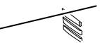


b
a
M 


 ON / MARCHE
OFF / ARRET
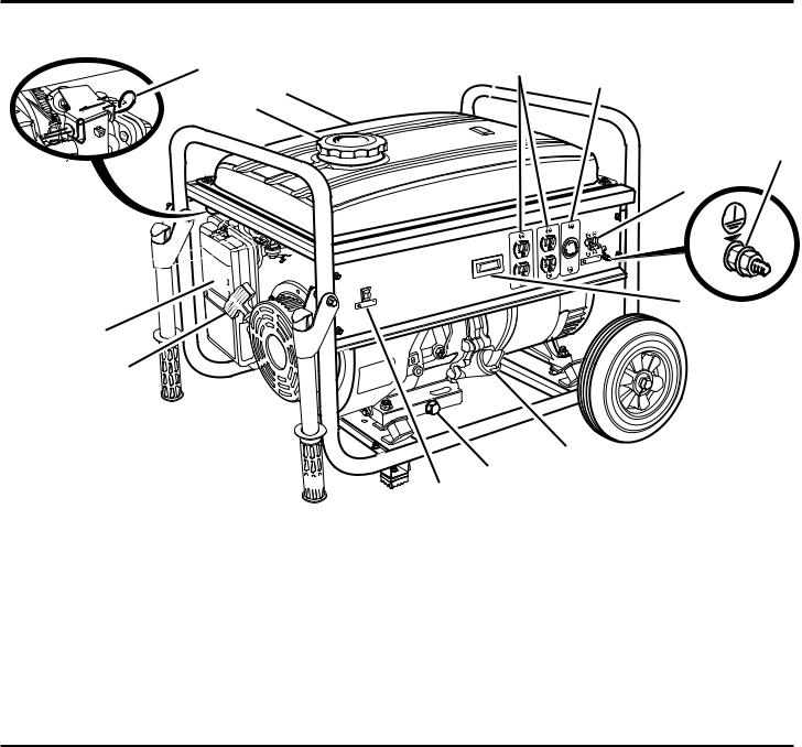
A - Recoil starter grip (poignée du démarreur à rappel, mango del arrancador retráctil)
B - Air filter (filtre à air, filtro de aire)
C - Choke lever (levier d’étrangleur, palanca del anegador) D - Fuel cap (bouchon de carburant, tapa del tanque)
E - Fuel tank (réservoir de carburant, tanque de combustible)
F- 120V AC 20 amp receptacles (prises 120 V c.a. 20 A, 120 V de CA 20 A receptáculos)
G- 120V/240V AC 30 amp receptacles (prises 120V/240V c.a. 30 A, 120V/240V de CA 30 A receptáculos)
F G
N
H
 ON / MARCHE
OFF / ARRET
00:00
J
L
K
I
H - AC circuit breaker (disjoncteur de c.a., disyuntor de circuito de CA)
I- Engine switch (commutateur du moteur, interruptor del motor)
J- Multifunctional digital display (afficheur numérique multifonctionnel, pantalla digital multifuncional)
K- Oil drainage bolt (vis de vidange d’huile, perno de drenaje de aceite)
L- Oil cap/dipstick (bouchon/jauge d’huile, tapa de relleno de aceite/varilla
medidora de aceite)
M- Handle (poignée, mango)
N - Ground terminal (borne de terre, terminal de conexión a tierra) O - Fuel valve (robinet de carburant, válvula de combustible)
ii
Fig. 2 |
2 |
|
|
|
|
|
1 |
|
|
3 |
10 |
|
|
|
|
|
8 |
|
5 |
|
|
4 |
|
|
6 |
|
|
2 |
|
|
|
9 |
|
7 |
|
Fig. 3 |
B |
|
A |
|
A - Socket wrench (clé à douille, llave de casquillo) |
|
|
B - Combination wrench (clé mixte, llave de combinación) |
Fig. 4 |
|
Fig. 5 |
|
ON / MARCHE |
|
|
OFF / |
ARRET |
|
|
|
ON / MARCHE |
|
OFF / ARRET |
A |
A 


 b
b 

C |
A - Frame (cadre, armazón)
B - Bolt (boulon, perno)
C - Foot (patin, pie)
b
c
d
e
A - Lock nut (écrou frein, tuerca de bloqueo) B - U-bracket (support en U, soporte en “U”) C - Axle (essieu, eje)
D - Wheel (roue, rueda)
E - Pin (goupille, pasadore)
Fig. 6 |
e |
f |
c |
ON / MARCHE |
|
OFF |
/ ARRET |
|
|
d
b
A - Frame (cadre, armazón) A B - Handle (poignée, mango) C - Hole (trou, agujero)
D - Bolt (boulon, perno)
E - Lock nut (écrou frein, tuerca de bloqueo) F - Spacer (pièces d’écartement, separador)
iii
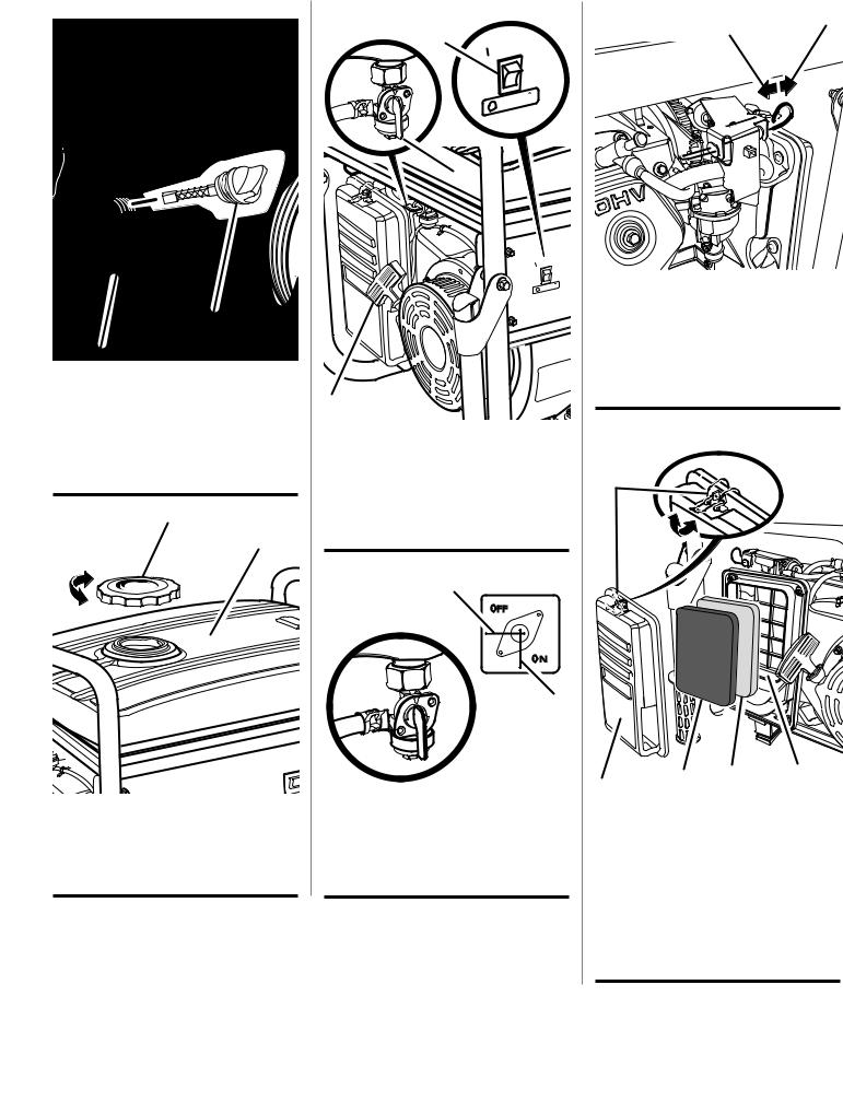
Fig. 7 |
Fig. 9 |
Fig. 11 |
A |
b |
|
|
b |
|
|
|
|
|
|
OFF |
/ ARR |
|
00:00
ON |
/ MARCHE |
|
OFF |
/ ARRET |
|
A
A
b
A - Oil cap/dipstick (bouchon/jauge d’huile, tapa de relleno de aceite/varilla medidora de aceite)
B - Lubricant fill hole (orifice de remplissage d’huile, agujero de llenado de aceite)
Fig. 8 A
b
0
A - Fuel cap (bouchon de carburant, tapa del tanque de combustible)
B - Fuel tank (réservoir de carburant, tanque de combustible)
ON / MARCHE |
|
OFF |
/ ARRET |
|
|
c
A - Fuel valve (robinet de carburant, interruptor del motor)
B - Engine switch (contacteur du moteur, válvula de co mbustible)
C - Recoil starter grip (poignée de démarreur à rappel, mango del arrancador retráctil)
Fig. 10
b
c
 A
A
A - Fuel valve (robinet de carburant, válvula de combustible)
B - Off (arret, apagado)
C - On (marche, encendido)
A - Pull choke out to start (Tirer le volet de départ vers l’extérieur pour démarrer l’appareil, tire del anegador hacia afuera para arrancar)
B - Push choke in to run (pousser le volet de départ à la position « Run » [Marche], tire del anegador hacia adentro para que funcione)
Fig. 12
A
b |
C |
D |
E |
|
|
|
A - Clasp (attache, tuerca del husillo)
B- Air filter cover (couvercle du filtre à air, tapa del filtro de aire)
C- Filter element (élément du filtre, elemento de filtro)
D- Filter gasket (garniture de filtre, junta del filtro)
E- Air filter unit (unité de filtre à air, unidad del filtro de aire)
iv

Fig. 13
ET
b
A
A - Oil drainage bolt (vis de vidange d’huile, perno de drenaje de aceite)
B - Oil cap/dipstick (bouchon/ jauge d’huile, tapa de relleno de aceite/varilla medidora de aceite)
Fig. 14
b
A
A - Spark plug (bougie, bujía)
B - Spark plug cap (capuchon de bougie, tapa de la bujía)
Fig. 15
A
b
A - Muffler outlet cover plate (couvercle de la sortie du silencieux, silenciador y el parachispas)
B - Hex bolts (boulon hex., perno hexagonal)
Fig. 16 A
c
b |
A - Screw (vis, tornillo)
B - Muffler outlet (sortie du silencieux, recubrimiento del silenciador)
C - Spark arrestor (pare-étincelles, parachispas) C - Wire brush (brosse métallique, cepillo de
alambre)
Fig. 17
b
 d
d
A |
c |
|
|
|
e |
A - Fuel line (conduite de carburant, conducto de combustible)
B - Fuel valve (robinet de carburant, válvula de combustible)
C - Petcock (robinet de carburant, llave de purga)
D - Off (arret, apagado)
E - On (marche, encendido)
Fig. 18
A
A - Carburetor drain screw (vis de vidange du carburateur, tornillo de drenaje del carburador)
v
|
|
TABLE OF CONTENTS |
|
Introduction.................................................................................................................................................................... |
2 |
|
Important Safety Instructions...................................................................................................................................... |
3-4 |
|
Specific Safety Rules...................................................................................................................................................... |
4 |
|
Symbols....................................................................................................................................................................... |
5-7 |
|
Electrical...................................................................................................................................................................... |
8-9 |
|
Features ....................................................................................................................................................................... |
10 |
|
Assembly................................................................................................................................................................. |
11-12 |
|
Operation................................................................................................................................................................. |
12-14 |
|
Maintenance............................................................................................................................................................ |
14-16 |
|
Troubleshooting............................................................................................................................................................ |
17 |
|
Warranty.................................................................................................................................................................. |
18-19 |
|
Parts Ordering / Service.................................................................................................................................. |
Back Page |
INTRODUCTION
This product has many features for making its use more pleasant and enjoyable. Safety, performance, and dependability have been given top priority in the design of this product, making it easy to maintain and operate.
 danger:
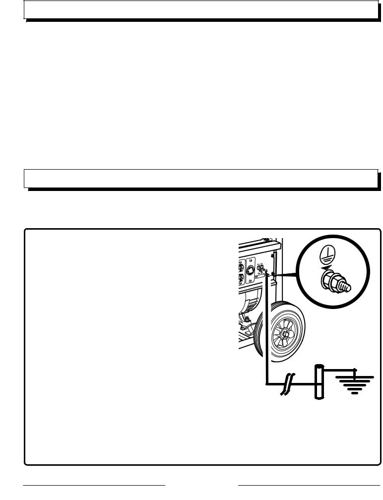
Grounding the Generator
To reduce the risk of shock or electrocution, generator must be properly grounded. The nut and ground terminal on the frame must always be used to connect the generator to a suitable ground source. The ground path should be made with #8 size wire. Connect the terminal of the ground wire between the lock washer and the nut, and tighten the nut fully. Connect the other end of the wire securely to a suitable ground source.
The National Electric Code contains several practical ways in which to establish a good ground source. If a steel or iron rod is used, it should be at least 5/8 in. diameter, and if a nonferrous rod is used, it should be at least 1/2 in. diameter and be listed as material for grounding. Drive the rod or pipe to a depth of 8 ft. If a rock bottom is encountered less than 4 ft. down, bury the rod or pipe in a trench.
All electrical tools and appliances operated from this generator must be properly grounded by use of a third wire or be “Double Insulated.”
It is recommended to:
 ON / MARCHE
OFF / ARRET
1.Use electrical devices with 3-prong grounded plugs.
2.Use an extension cord with a 3-pole receptacle and a 3-prong plug at opposite ends to ensure continuity of the ground protection from the generator to the appliance.
Check and adhere to all applicable federal, state, and local regulations relating to grounding specifications. Consult a qualified electrician or service personnel if the grounding instructions are not completely understood or if in doubt as to whether the generator is properly grounded.
Page 2 — English
important safety instructions
 DANGER:
Carbon Monoxide. Using a generator indoors will KILL YOU IN MINUTES.
Generator exhaust contains high levels of carbon monoxide (CO), a poisonous gas you cannot see or smell. If you can smell the generator exhaust, you are breathing CO. But even if you cannot smell the exhaust, you could be breathing CO.
Never use a generator inside homes, garages, crawlspaces, or other partly enclosed areas. Deadly levels of carbon monoxide can build up in these areas. Using a fan or opening windows and doors does NOT supply enough fresh air.
ONLY use a generator outdoors and far away from open windows, doors, and vents. These openings can pull in generator exhaust.
Even when you use a generator correctly, CO may leak into the home. ALWAYS use a battery-powered or battery-backup CO alarm in the home.
If you start to feel sick, dizzy, or weak after the generator has been running, move to fresh air RIGHT AWAY. See a doctor. You could have carbon monoxide poisoning.
 WARNING:
Read and understand all instructions. Failure to follow all instructions listed below may result in electrocution, fire, and/or carbon monoxide poisoning, which will cause death or serious injury.
 WARNING:
National Electric Code requires generator to be grounded to an approved earth ground. Before using the ground terminal, consult a qualified electrician, electrical inspector, or local agency having jurisdiction for local codes or ordinances that apply to the intended use of the generator.
SAVE THESE INSTRUCTIONS
This manual contains important instructions that should be followed during installation and maintenance of the generator and batteries.
Do not allow children or untrained individuals to use this unit.
Never start or run the engine inside a closed or partially enclosed area. Breathing exhaust fumes will kill you.
Always wear eye protection with side shields marked to comply with ANSI Z87.1 as well as hearing protection when operating this equipment.
Keep all bystanders, children, and pets at least 10 feet away.
Wear sturdy and dry shoes or boots. Do not operate while barefoot.
Do not operate generator when you are tired or under the influence of drugs, alcohol, or medication.
Keep all parts of your body away from any moving parts and all hot surfaces of the unit.
Do not touch bare wire or receptacles.
Do not use generator with electrical cords which are worn, frayed, bare, or otherwise damaged.
Before storing, allow the engine to cool and drain fuel from the unit.
Do not operate or store the generator in rain, snow, or wet weather.
Store the generator in a well-ventilated area with the fuel tank empty. Fuel should not be stored near the generator .
Empty fuel tank, close fuel valve, and restrain the unit from moving before transporting in a vehicle.
Allow engine to cool for five minutes before refueling.
To reduce the risk of fire and burn injury, handle fuel with care. It is highly flammable.
Do not smoke while handling fuel.
Store fuel in a container approved for gasoline.
Position the unit on level ground, stop engine, and allow to cool before refueling.
Loosen fuel cap slowly to release pressure and to keep fuel from escaping around the cap.
Tighten the fuel cap securely after refueling.
Wipe spilled fuel from the unit.
Never attempt to burn off spilled fuel under any circumstances.
Generators vibrate in normal use. During and after the use of the generator, inspect the generator as well as extension cords and power supply cords connected to it for damage resulting from vibration. Have damaged items repaired or replaced as necessary. Do not use plugs or cords that show signs of damage such as broken or cracked insulation or damaged blades.
For power outages, permanently installed stationary generators are better suited for providing back-up power to the home. Even a properly connected portable generator can become overloaded. This may result in overheating or stressing the generator components, possibly leading to generator failure.
Use only authorized replacement parts and accessories and follow instructions in the Maintenance section of this manual. Use of unauthorized parts or failure to follow maintenance instructions may create a risk of shock or injury.
Page 3 — English
important safety instructions
Maintain the unit per maintenance instructions in this |
Inspect the unit before each use for loose fasteners, fuel |
Operator’s Manual. |
leaks, etc. Replace damaged parts. |
SPECIFIC SAFETY RULES
 WARNING:
When this generator is used to supply a building wiring system: generator must be installed by a qualified electrician and connected to a transfer switch as a separately derived system in accordance with NFPA 70, National Electrical Code. The generator shall be connected through a transfer switch that switches all conductors other than the equipment grounding conductor. The frame of the generator shall be connected to an approved grounding electrode. Failure to isolate the generator from power utility can result in death or injury to electric utility workers.
Exhaust contains poisonous carbon monoxide, a colorless, odorless gas. Breathing exhaust can cause loss of consciousness and can lead to death. If running in a confined or partially-enclosed area, the air may contain a dangerous amount of carbon monoxide. To keep exhaust fumes from building up, always provide adequate ventilation.
Always use a battery-powered carbon monoxide detector when running the generator. If you begin to feel sick, dizzy, or weak while using the generator, shut it off and get to fresh air immediately. See a doctor. You may have carbon monoxide poisoning.
Place the generator on a flat, stable surface.
Operate in a well-ventilated, well-lit area isolated from working areas to avoid noise interference.
Operating the generator in wet conditions could result in electrocution. Keep the unit dry.
Keep the generator a minimum of 3 feet away from all types of combustible material.
Do not operate generator near hazardous material.
Do not operate generator at a gas or natural gas filling station.
Do not touch the muffler or cylinder during or immediately after use; they are HOT and will cause burn injury.
This generator has a neutral bonded condition. This means the neutral conductor is electrically connected to the frame of the machine.
Do not connect to a building’s electrical system unless a transfer switch has been properly installed by a qualified electrician.
Do not allow the generator’s gas tank to overflow when filling. Fill to 1 in. below the top neck of the gasoline tank to allow for fuel expansion. Check the ventilation hole inside the fuel tank cap for debris. Do not block the vent.
Do not smoke when filling the generator with gasoline.
Shut down the engine and allow to cool completely before adding gasoline or lubricant to the generator.
Do not remove the oil dipstick or the fuel tank cap when the engine is running.
Pay close attention to all safety labels located on the generator.
Keep children a minimum of 10 feet away from the generator at all times.
The unit operates best in temperatures between 23°F and 104°F with a relative humidity of 90% or less.
Specific modifications for high-altitude performance are needed if the generator will always be operated at altitudes above 5,000 feet. Contact your nearest authorized service center for more information and to have these modifications performed.
Operating voltage and frequency requirement of all electronic equipment should be checked prior to plugging them into this generator. Damage may result if the equipment is not designed to operate within a +/- 10% voltage variation, and +/- 3 hz frequency variation from the generator name plate ratings. To reduce the risk of damage, always have an additional load plugged into the generator if solid state equipment (such as a television set) is used. A power line conditioner is recommended for some solid state applications.
Save these instructions. Refer to them frequently and use them to instruct others who may use this product. If you loan someone this product, loan them these instructions also.
Page 4 — English
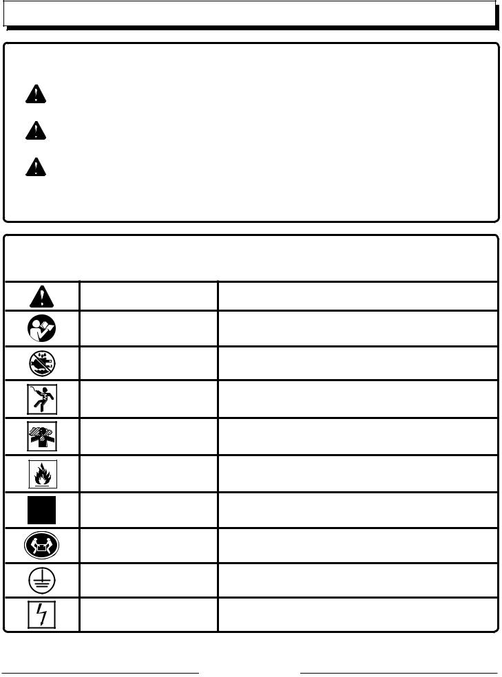
SYMBOLS
The following signal words and meanings are intended to explain the levels of risk associated with this product.
SYMBOL |
SIGNAL |
MEANING |
|
|
|
|
DANGER: |
Indicates an imminently hazardous situation, which, if not avoided, will result |
|
in death or serious injury. |
|
|
|
|
|
|
|
|
WARNING: |
Indicates a potentially hazardous situation, which, if not avoided, could result |
|
in death or serious injury. |
|
|
|
|
|
|
|
|
CAUTION: |
Indicates a potentially hazardous situation, which, if not avoided, may result in |
|
minor or moderate injury. |
|
|
|
|
|
|
|
|
CAUTION: |
(Without Safety Alert Symbol) Indicates a situation that may result in property |
|
damage. |
|
|
|
Some of the following symbols may be used on this product. Please study them and learn their meaning. Proper interpretation of these symbols will allow you to operate the product better and safer.
SYMBOL |
NAME |
DESIGNATION/EXPLANATION |
|
Safety Alert |
Indicates a potential personal injury hazard. |
|
Read Operator’s Manual |
To reduce the risk of injury, user must read and understand |
|
operator’s manual before using this product. |
|
|
|
|
|
Wet Conditions Alert |
Do not expose to rain or use in damp locations. |
|
Electric Shock |
Failure to use in dry conditions and to observe safe practices can |
|
result in electric shock. |
|
|
|
|
|
|
Running generator gives off carbon monoxide, an odorless, color- |
|
Toxic Fumes |
less, poison gas. Breathing carbon monoxide can cause nausea, |
|
|
fainting, or death. |
|
Fire/Explosion |
Fuel and its vapors are extremely flammable and explosive. Fire |
|
or explosion can cause severe burns or death. |
|
|
|
|
|
Hot Surface |
To reduce the risk of injury or damage, avoid contact with any hot |
|
surface. |
|
|
|
|
|
Lifting Hazard |
To reduce the risk of serious injury, avoid attempting to lift the |
|
generator alone. |
|
|
|
|
|
Ground |
Consult with local electrician to determine grounding requirements |
|
before operation. |
|
|
|
|
|
Electrocution |
Failure to properly ground generator can result in electrocution, |
|
especially if the generator is equipped with a wheel kit. |
|
|
|
Page 5 — English

SYMBOLS
Some of the following symbols may be used on this product. Please study them and learn their meaning. Proper interpretation of these symbols will allow you to operate the product better and safer.
SYMBOL |
NAME |
DESIGNATION/EXPLANATION |
|
|
|
V |
Volts |
Voltage |
|
|
|
A |
Amperes |
Current |
|
|
|
Hz |
Hertz |
Frequency (cycles per second) |
|
|
|
W |
Watt |
Power |
|
|
|
hrs |
Hours |
Time |
|
|
|
gal |
Gallon |
Volume |
|
|
|
qt |
Quart |
Volume |
|
|
|
Page 6 — English
Product does not include ground rod or copper wire. National Electric Code requires generator to be properly grounded to an approved earth ground. Call an electrician for local grounding requirements.
Le produit ne comprend pas de piquet de terre ou de fil en cuivre. Le code electrique americain symbols(National Electric Code) requiert un générateur pour une bonne mise à la terre approuvée. Appeler un
électricien pour connaître les exigences locales de mise à la terre.
El producto no incluye el ealambre de cobre ni la barra de conexión a tierra. Los Reglamentos
Using a generator indoors WILL KILL YOU IN MINUTES.
|
|
|
|
|
|
Product does not include ground rod |
copper wire. National Electric Code requires generator to be |
|
|
|
|
|
Nacionales de Electricidad exigen que el generador esté debidamente conectado a una tierra aprobada. |
||||||
|
Generator exhaust contains carbon monoxide. This is a poison you |
|
|
properly grounded to an approved earth ground. Call an electrician for local grounding requirements. |
|
||||
|
cannot see or smell. |
|
|
|
Le produit ne comprend pas de piquet de terre ou de fil en cuivre. Le code electrique americain |
|
|||
SAFETY LABELS |
|
|
Comuniquese con un electrista para todo lo relacionado con los requistos de conexión a tierra. |
||||||
|
|
|
|
|
(National Electric Code) requiert un générateur pour une bonne mise à la terre approuvée. Appeler un |
|
|||
|
|
|
|
|
électricien pour connaître les exigences locales de mise à la terre. |
|
|||
|
|
|
Failure to prop- |
|
|
||||
|
|
|
|
|
|
El producto no incluye el ealambre de cobre ni la barraUsingde conexióna generatora tierra. Los Reglamentosindoors WILL KILL YOU IN MINUTES. |
|||
|
|
|
|
|
|
Nacionales de Electricidad exigen que el generador esté debidamente conectado a una tierra aprobada. |
|
||
The information below can be found on the generator. For |
|
erly groundComuniquese con un electristagenpara-todo lo relacionado con los requistos de conexión a tierra. |
|
||||||
|
erator can result |
Generator exhaust contains carbon monoxide. This is a poison you |
|||||||
|
NEVER use inside |
home or garage, |
Only use OUTSIDE and far away from |
|
cannot see or smell. |
|
|||
|
EVEN IF doors |
windows are open. |
windows, doors, and vents. |
|
|
|
|
|
|
your safety, please study and understand all of the labels |
|
in electrocution, |
|
|
|||||
before starting the generator. |
|
|
|
|
|
||||
|
|
|
|
HOT SURFACE |
|
|
|||
|
L’utilisation d’une génératrice à l’intérieur PEUT HOTVOUS TUERSURFACE |
especially if the |
NEVER use inside a home or garage, |
Only use OUTSIDE and far away from |
|||||
|
|
SURFACES TRÉS CHAUDE |
|||||||
If any of the labels come off the unit or become hard to read, |
|
g e n e r a t o r i s |
EVEN IF doors and windows are open. |
windows, doors, and vents. |
|||||
|
ENQUELQUES MINUTES. |
|
|
|
|
|
|
||
|
Les génératrices produisent du monoxyde de carbone, un gaz mortel |
|
|
SUPERFICIES CALIENTE |
|
|
|||
contact an authorized service center for replacement. |
|
equipped with a |
|
|
|||||
|
incolore et inodore. |
|
|
|
|
||||
|
|
|
SURFACES TRÉS CHAUDE |
|
|
||||
You WILL be KILLED or SERIOUSLY HURT if you do not |
|
wheel kit. |
|
|
|||||
Do not expose to rain or use in damp locations. |
|||||||||
follow the Operator’s Manual instructions. |
Utiliser uniquement À L’EXTÉRIEUR |
||||||||
|
NE JAMAIS utiliser à l’intérieur d’une |
|
|
Add lubricant to full mark to start. Engine will not start or will shut off |
|
||||
|
maison ou d’un garage, MÊME SI les |
et loinSUPERFICIESdes fenêtres, des portesCALIENTEet |
if lubricant is too low. |
|
|||||
|
portes et les fenêtres sont ouvertes. |
des évents. |
|
|
Ajouter de lubrifiant jusqu'au repère de remplissage pour dèmarrer. |
|
|||
|
Using a generatorLe moteur neindoorsdémarrera pas ou s'arrêteraWILLsi le niveau de lubrifiantKILL YOU IN MINUTES. |
||||||||
Risk of Fire. Do not add fuel while the product is operat- |
|
|
est bas. |
|
|||||
ing. |
|
|
|
|
Generator exhaust contains carbon monoxide. This is a |
||||
Añada lubricante hasta la marca de ileno para arrancar. El motor no arrancará o se apagará si el nivel de lubricante está demasiado bajo.
poison you cannot see or smell.
NEVER use inside a home or garage, EVEN IF doors and
windows are openDANGER. PELIGRO
Risk of Fire. Check for any fuel overflow or leaking. Stop the engine before refueling.
|
|
|
Only use OUTSIDE and far away |
from windows, doors, |
||
Exhaust contains poisonous carbon monoxide gas that can |
|
Risque d’incendie. Vérifier l'absence de débordement ou de fuite de carburant. |
|
|||
|
Add lubricant to full mark to start. Engine will not start or will shut off |
|||||
|
NUNCA lo use dentro de su hogar del |
Sólo utilícelo AL AIRE LIBRE y lejos |
|
Arrêter le moteur avant de fair le plein. |
|
|
|
|
Riesgo de incendio. Revise si hay algún derrame o fuga de combustible. Apague el |
||||
|
garaje, INCLUSO con las puertas y las |
de ventanas, puertas y respiraderos. |
|
motor antes de poner combustible. |
|
|
cause unconscious- |
ventanas abiertas. |
|
|
if lubricant is too low. |
|
|
|
|
and vents. |
|
|
||
ness or DEATH. Oper- |
|
|
|
Ajouter de lubrifiant jusqu'au repère de remplissage pour dèmarrer. |
||
|
DANGER |
Le moteur ne démarrera pas ou s'arrêtera si le niveau de lubrifiant |
||||
ate in well-ventilated, |
|
est bas.PELIGRO |
|
|
||
You WILL be KILLED or SERIOUSLY HURT if you do not |
|
Añada lubricante hasta la marca de ileno para arrancar. El motor no |
||||
|
Generator is a potential source of electric shock. Do not expose to |
Failure to properly ground generator can result in electrocution, |
||||
outdoor areas away |
follow the Operator’s Manual instructions. |
moisture, rain, or snow. Do not operate with wet hands or feet. |
especially if the generator is equipped with a wheel kit. |
|||
|
|
|
arrancará o se apagará si el nivel de lubricante está demasiado bajo. |
|||
|
Ne pas procéder de la manière décrite dans ce Manuel d’utilisation |
Le générateur est une source potentielle de chocs électriques. Ne pas exposer à |
Une mauvaise mise à la terre du générateur peut causer une électrocution, |
|||
from open windows or |
entraînera des BLESSURES GRAVES voire la MORT. |
l’humidité, la pluie ou la neige. Ne pas utiliser avec les mains ou les pieds mouillés. |
surtout si le générateur est équipé d’un kit de roue. |
|||
instrucciones del Manual del operador. |
lluvia, nin a la nieve. No opere con manos o pies húmedos. |
La omisión de conectar a tierra adecuadamente el generador puede resultar en |
||||
|
SE MATARÁ o LESIONARÁ GRAVEMENTE si no sigue las |
El generador es una fuente de descarga eléctrica. No lo exponga a humedad, la |
||||
|
|
|
|
|
electrocución, especialmente si el generador está equipado con un kit de ruedas. |
|
doors. |
|
|
Exhaust contains poisonous carbon monoxide gas that can cause |
|
|
|
Risk of fire. Do not add fuel while the product is operating. |
unconsciousness or DEATH. Operate in well ventilated, outdoor areas |
|
|
|||
|
away from open windows or doors. |
|
|
|||
|
Risque d’incendie. Ne pas ajouter de carburant pendant l’utilisation |
Do not expose to rain or use in damp locations. |
||||
|
L’échappement contient le gaz monoxyde de carbone toxique qui peut causer |
|||||
|
de l’appareil. |
|
l’inconscience ou la MORT. Fonctionner dans les secteurs bien ventilés et |
Ne pas exposer à la pluie ou l’humidité. |
||
|
Riesgo del incendio. No agregue combustible cuando el producto |
extérieurs loin d’ouvre des fenêtres ou des portes. |
No exponga a la lluvia ni use en lugares húmedos. |
|||
|
esté functionando. |
|
El escape contiene gas venenoso de monóxido de carbono que puede causar |
|||
pérdida del conocimiento o MUERTE. Opere en áreas exteriores bien ventiladaslejos de puertas o ventanas abiertas.
|
DANGER |
PELIGRO |
Fuel warning |
Risk of Fire. Check for any fuel overflow or leaking. Stop the engine before refueling. |
|
No smoking when filling with gasoline. Do |
Risque d’incendie. Vérifier l'absence de débordement ou de fuite de carburant. |
|
Arrêter le moteur avant de fair le plein. |
|
|
not overfill. Full level is 1 in. below the top |
Riesgo de incendio. Revise si hay algún derrame o fuga de combustible. Apague el |
|
of the fuel neck. Stop the engine for five |
motor antes de poner combustible. |
|
|
|
|
minutes before refueling to avoid the heat |
|
|
from the muffler igniting fuel vapors. |
|
|
PELIGRO |
|
|
|
engine LUBRICANT warning |
|
|
|
|
||
DANGER |
|
|
||||
You must add lubricant before first operating the genera- |
|
|
Failure to properly ground gener |
|||
tor. The oil reservoir capacity is 1.16 qt. Always check |
|
|
||||
the lubricant level before each operation. The lubricant |
|
|
especially if the generator is eq |
|||
|
|
Une mauvaise mise à la terre du gé |
||||
anière décrite dans ce Manuel d’utilisation |
Le générateur est une source potentielle de chocs électriques. Ne pas exposer à |
surtout si le générateur est équipé d |
||||
ES GRAVES voire la MORT. |
l’humidité, la pluie ou la neige. Ne pas utiliser avec les mains ou les pieds mouillés. |
|||||
level should always register between |
|
|
|
La omisión de conectar a tierra adec |
||
Á GRAVEMENTE si no sigue las |
El generador es una fuente de descarga eléctrica. No lo exponga a humedad, la |
|||||
the hatched areas on the dipstick. The |
|
pies húmedos. |
|
electrocución, especialmente si el g |
||
l del operador. |
lluvia, nin a la nieve. No opere con manos o |
|
|
|
||
unit is equipped with a sensor which will |
|
|
|
|
|
|
automatically shut off the engine if the |
Product does not include ground rod or copper wire. National Electric Code requires generator to be |
|
||||
|
Exhaust |
contains poisonous carbon monoxide gas that can cause |
|
|
||
|
|
properly grounded to an approved earth ground. Call an electrician for local grounding requirements. |
|
|||
|
unconsciousness or DEATH. Operate in well ventilated, outdoor areas |
|
|
|||
lubricant level falls below a safe limit. |
|
|
|
|
|
|
|
away from open windows or doors. |
|
|
|
|
|
s ajouter de carburant pendant l’utilisation |
|
Le produit ne comprend pas de piquet de terre ou de fil en cuivre. Le code electrique americain |
or use in d |
|||
L’échappement contient le gaz monoxyde de carbone toxique qui peut causer |
Do not expose to rain |
|||||
grounding warning |
|
(National Electric Code) requiert un générateur pour une bonne mise à la terre approuvée. Appeler un |
|
|||
l’inconscience ou la MORT. Fonctionner dans les secteurs bien ventilés et |
Ne pas exposer à la pluie ou l’humid |
|||||
agregue combustible cuando el producto |
|
électricien pour connaître les exigences locales de mise à la terre. |
||||
extérieurs loin d’ouvre des fenêtres ou des portes. |
No exponga a la lluvia ni use en lug |
|||||
National Electric Code requires gen- |
|
|
|
|||
|
El escape contiene gas venenoso de monóxido de carbono que puede causar |
|
|
|||
|
|
El producto no incluye el ealambre de cobre ni la barra de conexión a tierra. Los Reglamentos |
||||
|
pérdida del conocimiento o MUERTE. Opere en áreas exteriores bien |
|
|
|||
erator to be grounded to an approved |
Nacionales de Electricidad exigen que el generador esté debidamente conectado a una tierra aprobada. |
|||||
earth ground. |
ventiladaslejos de puertas o ventanas abiertas. |
|
|
|||
|
Comuniquese con un electrista para todo lo relacionado con los requistos de conexión a tierra. |
|||||
HOT SURFACE
SURFACES TRÉS CHAUDE
SUPERFICIES CALIENTE
Hot SURFACE warning
Do not touch the muffler or aluminum cylinder of the engine. They are very HOT and will cause severe burns. Don’t put any flammable or combustible materials in the direct path of the exhaust.
Page 7 — English

electrical
extension cord cable size
Refer to the table below to ensure the cable size of the extension cords you use are capable of carrying the required load. Inadequate size cables can cause a voltage drop, which can damage the appliance and overheat the cord.
Current in |
Load in Watts |
|
Maximum Allowable Cord Length |
|
|||
Amperes |
At 120V |
At 240V |
#8 Wire |
#10 Wire |
#12 Wire |
#14 Wire |
#16 Wire |
|
|
|
|
|
|
|
|
2.5 |
300 |
600 |
|
1000 ft. |
600 ft. |
375 ft. |
250 ft. |
|
|
|
|
|
|
|
|
5 |
600 |
1200 |
|
500 ft. |
300 ft. |
200 ft. |
125 ft. |
|
|
|
|
|
|
|
|
7.5 |
900 |
1800 |
|
350 ft. |
200 ft. |
125 ft. |
100 ft. |
|
|
|
|
|
|
|
|
10 |
1200 |
2400 |
|
250 ft. |
150 ft. |
100 ft. |
50 ft. |
|
|
|
|
|
|
|
|
15 |
1800 |
3600 |
|
150 ft. |
100 ft. |
65 ft. |
|
20 |
2400 |
4800 |
175 ft. |
125 ft. |
75 ft. |
|
|
|
|
|
|
|
|
|
|
25 |
3000 |
6000 |
150 ft. |
100 ft. |
|
|
|
|
|
|
|
|
|
|
|
30 |
3600 |
7200 |
125 ft. |
65 ft. |
|
|
|
|
|
|
|
|
|
|
|
40 |
4800 |
9600 |
90 ft. |
|
|
|
|
|
|
|
|
|
|
|
|
electric motor loads
It is characteristic of common electric motors in normal operation to draw up to six times their running current while starting. This table may be used to estimate the watts required to start “Code G” electric motors; however, if an electric motor fails to start or reach running speed, turn off the appliance or tool immediately to avoid equipment damage. Always check the requirements of the tool or appliance being used compared to the rated output of the generator.
Motor Size (H.P.) |
Running Watts |
Watts Required to Start Motor |
|
||
Repulsion Induction |
Capacitor |
|
Split Phase |
||
|
|
|
|||
1/8 |
275 |
600 |
850 |
|
1200 |
|
|
|
|
|
|
1/6 |
275 |
600 |
850 |
|
2050 |
|
|
|
|
|
|
1/4 |
400 |
850 |
1050 |
|
2400 |
|
|
|
|
|
|
1/3 |
450 |
975 |
1350 |
|
2700 |
|
|
|
|
|
|
1/2 |
600 |
1300 |
1800 |
|
3600 |
|
|
|
|
|
|
3/4 |
850 |
1900 |
2600 |
|
— |
|
|
|
|
|
|
1 |
1100 |
2500 |
3300 |
|
— |
|
|
|
|
|
|
CAUTION:
Operating voltage and frequency requirement of all electronic equipment should be checked prior to plugging them into this generator. Damage may result if the equipment is not designed to operate within a +/- 10% voltage variation, and +/- 3 hz frequency variation from the generator name plate ratings. To avoid damage, always have an additional load plugged into the generator if solid state equipment (such as a television set) is used. A power line conditioner is recommended for some solid state applications.
Page 8 — English

electrical
generator Capacity
Make sure the generator can supply enough continuous (running) and surge (starting) watts for the items you will power at the same time. Follow these simple steps.
1. Select the items you will power at the same time.
2. Totalthe continuous (running) watts of these items. This is the amount of power the generator must produce to keep the items running. See the wattage reference chart at right.
3. Estimate how many surge (starting) watts you will need.
Surge wattage is the short burst of power needed to start electric motor-driven tools or appliances such as a circular saw or refrigerator. Because not all motors start at the same time, total surge watts can be estimated by adding only the item(s) with the highest additional surge watts to the total rated watts from step 2.
Example: |
|
|
|
|
|
|
Tool or Appliance |
|
Continuous |
|
Surge |
||
|
|
|||||
|
(Running) Watts |
(Starting) Watts |
||||
|
|
|||||
|
|
|
|
|
|
|
Window AC, |
|
1200 |
|
1800 |
|
|
10,000 BTU |
|
|
|
|||
|
|
|
|
|
|
|
|
|
|
|
|
|
|
Refrigerator |
|
700 |
|
2200 |
|
|
|
|
|
|
|
|
|
1/3 HP Well Pump |
|
1000 |
|
2000 |
|
|
|
|
|
|
|
|
|
27 in. Television |
|
500 |
|
0 |
|
|
|
|
|
|
|
|
|
Light (75 Watts) |
|
75 |
|
0 |
|
|
|
|
|
|
|
|
|
|
|
3475 Total |
2200 Highest |
|||
|
|
Running Watts |
Surge Watts |
|||
Total Continuous (Running) Watts |
3475 |
|
||||
Plus Highest Additional Surge Watts |
+ 2200 |
|
||||
|
|
|
|
|||
Equals Total Generator Output Required |
5675 |
|
||||
POWER MANAGEMENT
To prolong the life of the generator and attached devices, it is important to take care when adding electrical loads to the generator. There should be nothing connected to the generator outlets before starting its engine. The correct and safe way to manage generator power is to sequentially add loads as follows:
1.With nothing connected to the generator, start the engine as described later in this manual.
2.Plug in and turn on the first load, preferably the largest load you have.
3.Permit the generator output to stabilize (engine runs smoothly and attached device operates properly).
4.Plug in and turn on the next load.
5.Again, permit the generator to stabilize.
6.Repeat steps 4 and 5 for each additional load.
Never add more loads than the generator capacity. Take special care to consider surge loads in generator capacity as previously described.
CAUTION:
Do not overload the generator’s capacity. Exceeding the generator’s wattage/amperage capacity can damage the generator and/or electrical devices connected to it.
|
Estimated |
Estimated |
|
Application/Equipment |
Starting |
||
Run Watts |
|||
|
Watts |
||
|
|
||
|
|
|
|
Emergency / Home Standby |
|
|
|
|
|
|
|
Clock Radio |
50 |
50 |
|
|
|
|
|
Lights (qty. 4 x 75 W) |
300 |
300 |
|
|
|
|
|
Refrigerator |
700 |
2200 |
|
|
|
|
|
Furnace Fan |
800 |
2350 |
|
|
|
|
|
Water Well Pump |
1000 |
1500 |
|
|
|
|
|
Microwave |
1000 |
1000 |
|
|
|
|
|
Sump Pump |
1050 |
2200 |
|
|
|
|
|
Electric Range (per element) |
2100 |
2100 |
|
|
|
|
|
Job Site |
|
|
|
|
|
|
|
Electric Drill − 1/2 HP |
600 |
900 |
|
|
|
|
|
Airless Sprayer − 1/3 HP |
600 |
1200 |
|
|
|
|
|
Quartz Halogen Work Light |
1000 |
1000 |
|
|
|
|
|
Reciprocating Saw |
960 |
960 |
|
|
|
|
|
Air Compressor − 1 HP |
1600 |
4500 |
|
|
|
|
|
Circular Saw − 7-1/4 in. |
1400 |
2300 |
|
|
|
|
|
Planer/Jointer − 6 in |
1800 |
1800 |
|
|
|
|
|
Miter Saw − 10 in. |
1800 |
1800 |
|
|
|
|
|
Table Saw/Radial Arm Saw − 10 in. |
2000 |
2000 |
|
|
|
|
*Wattages listed are approximate. Check tool or appliance for actual wattage.
Page 9 — English

FEATURES
PRODUCT SPECIFICATIONS
Engine
Engine Type........................................................ |
389cc OHV |
Cooling System.................................................... |
Forced Air |
Starting System......................................................... |
Recoil |
Ignition System.............................................................. |
TMI |
Spark Plug................................................. |
Champion F7TC |
Engine Lubricant Volume......................................... |
1.16 qt. |
Fuel Volume............................................................. |
6.6 gal. |
Generator |
|
Rated Voltage...................................................... |
120V/240V |
Rated Amps........................................................ |
41.6/20.8A |
Running Output....................................................... |
5,000 W |
Starting Output....................................................... |
6,250 W |
Rated Frequency......................................................... |
60 Hz |
Dimensions |
|
Length......................................................................... |
31 in. |
Width........................................................................... |
26 in. |
Height.......................................................................... |
24 in. |
Weight.................................................................. |
167.6 lbs. |
KNOW YOUR GENERATOR
See Figure 1.
The safe use of this product requires an understanding of the information on the product and in this operator’s manual as well as a knowledge of the project you are attempting. Before use of this product, familiarize yourself with all operating features and safety rules.
AC circuit breakerS
The circuit breakers are provided to protect the generator against electrical overload. The circuit breaker may be reset by lifting the circuit breaker reset lever.
air filter
The air filter helps to limit the amount of dirt and dust drawn into the unit during operation.
choke lever
The choke lever is used when starting the engine.
fuel tank
The fuel tank has a capacity of 6.6 gallons.
fuel valve
The flow of fuel through the generator is controlled by the position of the fuel valve.
ground terminal
The ground terminal is used to assist in properly grounding the generator to help protect against electrical shock. Consult with a local electrician for grounding requirements in your area.
MULTIFUNCTIONAL DIGITAL DISPLAY
The multifunctional digital display indicates voltage, frequency, and hours of operation for the current usage period.
oil cap
Remove the oil fill cap to check and add lubricant to the generator when necessary.
oil drainage bolt
When changing the engine lubricant, the oil drainage bolt is loosened to allow old engine lubricant to be drained.
receptacleS
Your generator has the following single phase, 60 Hz outlets: two 120 Volt AC, 20 Amp duplex receptacles, and one 120/240 Volt AC, 30 Amp twist-lock receptacle. These can be used for operating appropriate appliances, electrical lighting, tools, and motor loads.
recoil starter grip
The recoil starter grip is used (along with the engine switch) to start the generator’s engine.
Page 10 — English
assembly
WARNING:
Do not attempt to operate the generator until assembly is complete. Failure to comply could result in possible serious personal injury.
LOOSE PARTS LIST
See Figure 2.
The following items are included with the generator:
Key |
|
|
No. |
Description |
Qty. |
1 |
Wheel................................................................... |
2 |
2 |
Spacers................................................................ |
4 |
3 |
Bolts..................................................................... |
2 |
4 |
Axles..................................................................... |
2 |
5 |
Lock Nuts............................................................. |
2 |
6 |
Bottle of Engine Lubricant................................... |
1 |
7 |
Pins...................................................................... |
2 |
8 |
Lock nuts ............................................................ |
6 |
9 |
Feet...................................................................... |
2 |
10 |
Handles................................................................ |
2 |
11 |
Spark plug wrench (not shown)........................... |
1 |
|
Operator’s Manual (not shown)............................ |
1 |
TOOLS NEEDED
See Figure 3.
The following tools (not included or drawn to scale) are needed for assembly:
Utility Knife
13 mm Socket Wrench
11 mm and 17 mm Box End Wrench
NOTE: Do not put fuel or lubricant in the generator before installing the legs and wheels.
UNPACKING
This product requires assembly.
Carefully cut the box down the sides then remove the machine and any accessories from the box. Make sure that all items listed in the packing list are included.
NOTE: This machine is heavy and requires a minimum of two people to lift. To avoid back injury, lift with your legs and not your back.
Inspect the unit carefully to make sure no damage occurred during shipping.
Do not discard the packing material until you have carefully inspected and satisfactorily operated the product.
If any parts are damaged or missing, please call 1-800-242-4672 for assistance.
WARNING:
If any parts are damaged or missing do not operate this product until the parts are replaced. Use of this product with damaged or missing parts could result in serious personal injury.
WARNING:
Do not attempt to modify this product or create accessories not recommended for use with this product. Any such alteration or modification is misuse and could result in a hazardous condition leading to possible serious personal injury.
WARNING:
Do not attempt to operate the generator until assembly is complete. Failure to comply could result in possible serious personal injury.
NOTE: Do not put fuel or lubricant in the generator before installing the feet and wheels.
installing feet
See Figure 4.
Raise the end of the generator where the recoil starter is located high enough to gain access to the frame bottom; securely position props underneath to support.
Locate the following items: 2 foot/leg assemblies
4 lock nuts
Insert bolts for a foot/leg assembly through the holes on one side of the frame as shown.
Install nuts and tighten securely.
Repeat with remaining foot.
WARNING:
Do not use this product if any parts on the Loose Parts List are already assembled to your product when you unpack it. Parts on this list are not assembled to the product by the manufacturer and require customer installation. Use of a product that may have been improperly assembled could result in serious personal injury.
installing the wheels
See Figure 5.
Wheels are provided to assist in moving the generator to the desired location and should be installed on the side opposite the recoil starter.
Locate the following items: 2 axles
2 wheels
2 lock nuts
2 pins
Page 11 — English
ASSEMBLY
Raise the end of the generator opposite the recoil starter high enough to gain access to the frame bottom; securely position props underneath to support.
Slide an axle through the hole in the frame as shown.
Install a nut on the inside of the frame. Using a wrench, hold the axle firmly while you securely tighten the nut.
Slide a wheel over the axle.
Insert a pin through the axle.
Repeat the process on the other side to install second wheel.
attaching the handles
See Figure 6.
Locate the following items: 2 bolts
2 nuts
2 handles
4 spacers
Insert a bolt through one of the handles. Insert the handle through a spacer as shown.
Insert the bolt through the hole in the frame from the outside.
Place a spacer over the bolt as shown.
Install a nut over the end of the bolt and tighten securely.
 warning:
Do not attempt to lift the unit by the handle assembly. If it is necessary to lift the generator, always grasp by the frame. Use proper lifting techniques to avoid back injury.
operation
DANGER: |
danger: |
Carbon Monoxide. Using a generator indoors will KILL YOU IN MINUTES.
Generator exhaust contains high levels of carbon monoxide (CO), a poisonous gas you cannot see or smell. If you can smell the generator exhaust, you are breathing CO. But even if you cannot smell the exhaust, you could be breathing CO.
Never use a generator inside homes, garages, crawlspaces, or other partly enclosed areas. Deadly levels of carbon monoxide can build up in these areas. Using a fan or opening windows and doors does NOT supply enough fresh air.
ONLY use a generator outdoors and far away from open windows, doors, and vents. These openings can pull in generator exhaust.
Even when you use a generator correctly, CO may leak into the home. ALWAYS use a battery-powered or bat- tery-backup CO alarm in the home.
If you start to feel sick, dizzy, or weak after the generator has been running, move to fresh air RIGHT AWAY. See a doctor. You could have carbon monoxide poisoning.
Failure to properly ground generator can result in electrocution, especially if the generator is equipped with a wheel kit. National Electric Code requires generator to be properly grounded to an approved earth ground. Call an electrician for local grounding requirements.
 WARNING:
Do not allow familiarity with this product to make you careless. Remember that a careless fraction of a second is sufficient to inflict serious injury.
 WARNING:
Do not use any attachments or accessories not recommended by the manufacturer of this product. The use of attachments or accessories not recommended can result in serious personal injury.
Before each use, inspect the entire product for damaged, missing, or loose parts such as screws, nuts, bolts, caps, etc. Tighten securely all fasteners and caps and do not operate this product until all missing or damaged parts are replaced. Please call 1-800-242-4672 or contact an authorized service center for assistance.
Page 12 — English
operation
APPLICATIONS
This generator is designed to supply electrical power for operating compatible electrical lighting, appliances, tools, and motor loads.
BEFORE OPERATING the UNIT
Only use OUTSIDE and far away from windows, doors, and vents.
NEVER use inside a home or garage, EVEN IF doors and windows are open.
Always position the generator on a flat firm surface.
CAUTION:
Attempting to start the engine before it has been properly filled with lubricant will result in equipment failure.
checking/adding lubricant
See Figure 7.
Engine lubricant has a major influence on engine performance and service life. For general, all-temperature use, SAE 10W-30 is recommended. Always use a 4-stroke motor lubricant that meets or exceeds the requirements for API service classification SJ.
NOTE: Non-detergent or 2-stroke engine lubricants will damage the engine and should not be used.
Unscrew the oil cap/dipstick and remove.
Wipe dipstick clean and re-seat in hole; do not rethread.
Remove dipstick again and check lubricant level. Lubricant level should fall between the hatched areas on the dipstick.
If level is low, add engine lubricant until the fluid level rises to the upper portion of the dipstick.
Replace and secure the oil cap/dipstick.
checking/adding fuel
See Figure 8.
Remove the fuel cap.
Fill the fuel tank to 1 in. below the top of the fuel neck.
Replace and secure the fuel cap.
NOTE: Always use unleaded gasoline with a pump octane rating of 86 or higher. Never use old, stale, or contaminated gasoline, and do not use an oil/gas mixture. Do not allow dirt or water into the fuel tank.
using fuel stabilizer
Fuel gets old, oxidizes, and breaks down over time. Adding a fuel stabilizer (not included) extends the usable life of fuel and helps prevent deposits from forming that can clog the fuel system. Follow fuel stabilizer manufacturer’s directions for correct ratio of stabilizer to fuel.
Add stabilizer to fuel tank, then fill with gasoline following previous instructions.
NOTE: Fuel stabilizer and gasoline can be mixed prior to filling the tank by using a gas can or other approved fuel container and shaking gently to combine.
Replace and secure the fuel tank cap.
Start and run the engine for at least 5 minutes to allow stabilizer to treat the entire fuel system.
OXYGENATED FUELS
DO NOT USE E85 FUEL. IT WILL VOID YOUR WARRANTY.
NOTE: Fuel system damage or performance problems resulting from the use of an oxygenated fuel containing more than the percentages of oxygenates stated previously are not covered under warranty.
Ethanol. Gasoline containing up to 10% ethanol by volume (commonly referred to as E10) or 15% ethanol by volume (commonly referred to as E15) are acceptable. E85 is not.
CAUTION:
On a level surface with the engine off, check the lubricant level before each use of the generator.
Starting the engine
See Figures 9 - 11.
NOTE: If location of generator is not level, the unit may not start or may shut down during operation.
Unplug all loads from the generator.
Turn the fuel valve to the ON position.
Put the engine switch in the ON position.
Pull choke.
Grasp the recoil starter and pull slowly until resistance is felt. Give the recoil starter a short, brisk pull to start the engine.
NOTE: Do not allow the recoil starter to snap back after starting; return it gently to its original place.
Let engine run for several seconds, then push choke in.
Stopping the engine
See Figures 9 - 11.
To stop the engine under normal operating conditions:
Remove any load from the generator.
Turn the fuel valve to the OFF position.
Put the engine switch in the OFF ( O ) position.
To stop the engine in an emergency situation:
Put the engine switch in the OFF ( O ) position.
MULTIFUNCTIONAL DIGITAL DISPLAY
The multifunctional digital display indicates voltage, frequency, and hours of operation for the current usage period.
Page 13 — English

maintenance
 WARNING:
When servicing, use only identical Homelite replacement parts. Use of any other parts may create a hazard or cause product damage.
 WARNING:
Always wear eye protection with side shields marked to comply with ANSI Z87.1. Failure to do so could result in objects being thrown into your eyes, resulting in possible serious injury.
Only the parts shown on the parts list are intended to be repaired or replaced by the customer. All other parts should be replaced at an authorized service center.
GENERAL MAINTENANCE
Before each use, inspect the entire product for damaged, missing, or loose parts such as screws, nuts, bolts, caps, etc. Tighten securely all fasteners and caps and do not operate this product until all missing or damaged parts are replaced. Please call 1-800-242-4672 or contact an authorized service center for assistance.
Keep the generator in a clean and dry environment where it is not exposed to dust, dirt, moisture, or corrosive vapors. Do not allow the cooling air slots in the generator to become clogged with foreign material such as leaves, etc.
Do not use a garden hose to clean the generator. Water entering the fuel system or other internal parts of the unit can cause problems that will decrease the life of the generator.
To clean the unit:
Use a soft bristle brush and/or vacuum cleaner to loosen and remove dirt and debris.
Clean air vents with low pressure air that does not exceed 25 psi.
Wipe the exterior surfaces of the generator with a damp cloth.
checking/CLEANING AIR FILTER
See Figure 12.
For proper performance and long life, keep air filter clean.
Open the clasp on the air filter cover. Remove cover and set aside.
Remove the filter element.
Remove the filter gasket. Wipe with a clean cloth and replace in the air filter unit.
If the filter element is dirty, clean with warm, soapy water. Rinse and let dry.
Apply a light coat of engine lubricant to the element, then squeeze it out.
Replace the element in the air filter unit.
Replace the air filter cover and close the clasp to secure .
NOTE: Do not run the generator without the air filter or gasket. Rapid engine wear will result.
changing engine lubricant
See Figure 13.
Remove the oil cap/dipstick.
Place a container underneath the oil drainage bolt to collect used lubricant as it drains.
Unscrew the oil drainage bolt and remove.
Allow lubricant to drain completely.
Reinstall the oil drainage bolt and tighten securely.
Refill with lubricant following the instructions in the
Checking/Adding Lubricant section.
Reinstall the oil cap/dipstick.
Note: Used lubricant should be disposed of at an approved disposal site. See your local oil retailer for more information.
spark plug maintenance
See Figure 14.
The spark plug must be properly gapped and free of deposits in order to ensure proper engine operation. To check:
Remove the spark plug cap.
Clean any dirt from around base of spark plug.
Remove spark plug using wrench (not included).
Inspect spark plug for damage, and clean with a wire brush before reinstalling. If insulator is cracked or chipped, spark plug should be replaced.
NOTE: If replacing, use the following recommended spark plug or equivalent: Champion F7TC.
Measure plug gap. The correct gap is 0.028−0.031 in.
(0.7-0.8 mm). To widen gap, if necessary, carefully bend the ground (top) electrode. To lessen gap, gently tap ground electrode on a hard surface.
Seat spark plug in position; thread in by hand to prevent cross-threading.
Tighten with wrench to compress washer. If spark plug is new, use 1/2 turn to compress washer appropriate amount. If reusing old spark plug, use 1/8 to 1/4 turn for proper washer compression.
NOTE: An improperly tightened spark plug will become very hot and could damage the engine.
Page 14 — English
 Loading...