


HGFC35
Table of contents
 Loading...
Hobart HGFC35, HGF35, HGFC65, HGF65F, HGF35F User Manual
...
701 S. RIDGE AVENUE
TROY, OHIO 45374-0001
937 332-3000
www.hobartcorp.com
HOBART HGF, HGD AND HGC SERIES
GAS FRYERS
WITH OR WITHOUT FILTER-IN-A-DRAWER
MODELS
HGF35 ML-126994
HGF45 ML-126995
HGF65 ML-126996
HGF85 ML-126997
HGFD35 ML-126416
HGFD45 ML-126417
HGFD65 ML-126418
HGFD85 ML-126419
HGFC35 ML-126420
HGFC45 ML-126421
HGFC65 ML-126422
HGFC85 ML-126423
HGFD45
FORM 35614 (February 2004)
HGF35F ML-135536
HGF45F ML-135537
HGF65F ML-135538
HGF85F ML-135539
HGD35F ML-126953
HGD45F ML-126956
HGD65F ML-126959
HGD85F ML-126962
HGC35F ML-126954
HGC45F ML-126957
HGC65F ML-126960
HGC85F ML-126963

– 2 –
IMPORTANT FOR YOUR SAFETY
THIS MANUAL HAS BEEN PREPARED FOR PERSONNEL QUALIFIED TO INSTALL GAS
EQUIPMENT, WHO SHOULD PERFORM THE INITIAL FIELD START-UP AND
ADJUSTMENTS OF THE EQUIPMENT COVERED BY THIS MANUAL.
POST IN A PROMINENT LOCATION THE INSTRUCTIONS TO BE FOLLOWED IN THE
EVENT THE SMELL OF GAS IS DETECTED. THIS INFORMATION CAN BE OBTAINED
FROM THE LOCAL GAS SUPPLIER.
IMPORTANT
IN THE EVENT A GAS ODOR IS DETECTED, SHUT
DOWN UNITS AT MAIN SHUTOFF VALVE AND
CONTACT THE LOCAL GAS COMPANY OR GAS
SUPPLIER FOR SERVICE.
FOR YOUR SAFETY
DO NOT STORE OR USE GASOLINE OR OTHER
FLAMMABLE VAPORS OR LIQUIDS IN THE
VICINITY OF THIS OR ANY OTHER APPLIANCE.
WARNING
IMPROPER INSTALLATION, ADJUSTMENT,
ALTERATION, SERVICE OR MAINTENANCE CAN
CAUSE PROPERTY DAMAGE, INJURY OR
DEATH. READ THE INSTALLATION, OPERATING
AND MAINTENANCE INSTRUCTIONS
THOROUGHLY BEFORE INSTALLING OR
SERVICING THIS EQUIPMENT.
IN THE EVENT OF A POWER FAILURE, DO NOT
ATTEMPT TO OPERATE THIS DEVICE.
© HOBART CORPORATION, 2004

– 3 –
TABLE OF CONTENTS
GENERAL ............................................................................................................................................ 5
SPECIFICATIONS......................................................................................................................... 5
OPTIONS AND FEATURES......................................................................................................... 6
BATTERY CONFIGURATIONS ................................................................................................... 6
FIELD-INSTALLED ACCESSORIES ........................................................................................... 8
FACTORY-INSTALLED ACCESSORIES.................................................................................... 8
HGF SERIES FRYMATE (Dump Station) .................................................................................... 8
INSTALLATION ................................................................................................................................... 9
UNPACKING ................................................................................................................................. 9
LOCATION ................................................................................................................................... 10
INSTALLATION CODES AND STANDARDS ........................................................................... 10
ASSEMBLY .................................................................................................................................. 11
GAS CONNECTIONS ................................................................................................................. 12
GAS PRESSURES AND ORIFICES ......................................................................................... 12
TESTING THE GAS SUPPLY PIPING SYSTEM...................................................................... 12
LEVELING FRYER ...................................................................................................................... 13
FLUE CONNECTIONS ............................................................................................................... 13
ELECTRICAL CONNECTIONS.................................................................................................. 13
OPERATION...................................................................................................................................... 14
BEFORE FIRST USE.................................................................................................................. 14
FILLING FRY TANK WITH SHORTENING ............................................................................... 14
LIGHTING INSTRUCTIONS FOR HGF FRYER WITH MANUAL PILOT IGNITION............. 15
LIGHTING INSTRUCTIONS FOR MANUAL PILOT IGNITION (HGFD/HGFC SERIES) ..... 16
STARTUP WITH ELECTRONIC IGNITION .............................................................................. 16
HGFD SERIES .................................................................................................................................. 17
CONTROLS ................................................................................................................................. 17
PROGRAMMING ......................................................................................................................... 18
MELT OPERATION ..................................................................................................................... 19
USING THE FRYER (AFTER STARTUP) ................................................................................. 20
SHUTDOWN ................................................................................................................................20
EXTENDED SHUTDOWN .......................................................................................................... 20

– 4 –
TABLE OF CONTENTS (cont.)
HGFC SERIES .................................................................................................................................. 21
CONTROLS ................................................................................................................................. 21
PROGRAMMING ......................................................................................................................... 22
TEMPERATURE AND TIME PROGRAMMING ........................................................................ 25
USING THE FRYER (After Startup) ........................................................................................... 29
SHUTDOWN ................................................................................................................................30
EXTENDED SHUTDOWN .......................................................................................................... 30
FRYING GUIDELINES (All Models) ........................................................................................... 30
DAILY FILTERING....................................................................................................................... 31
HIGH LIMIT DEVICE (All Models) .............................................................................................. 32
DRAIN INTERLOCK (HGD and HGC Series)........................................................................... 32
SHORTENING LIFE (All Models) ............................................................................................... 32
CLEANING......................................................................................................................................... 33
DAILY ........................................................................................................................................... 33
WEEKLY OR AS REQUIRED .................................................................................................... 33
MAINTENANCE................................................................................................................................. 34
LUBRICATION............................................................................................................................. 34
BURNER FLUE............................................................................................................................ 34
SERVICE...................................................................................................................................... 34
TROUBLESHOOTING GUIDE......................................................................................................... 35
ALARMS AND ERROR MESSAGES (HGD and HGC Series)................................................ 36
– 5 –
Installation, Operation and Care of
MODELS HGF, HGD and HGC SERIES GAS FRYERS
SAVE THESE INSTRUCTIONS
GENERAL
Hobart HGF, HGD and HGC Series Gas Fryers are produced with quality workmanship and material.
Proper installation, usage and maintenance of your fryer will result in many years of satisfactory
performance.
It is suggested that you thoroughly read this entire manual and carefully follow all of the instructions
provided.
The Mobile Filter, used for filter-ready fryers, is covered in a separate Instruction Manual. Fryers
equipped with Filter-In-A-Drawer are covered in a separate Instruction Manual. Follow the instructions
in the appropriate manual for filtering, draining and dumping shortening.
Hobart HGF, HGD and HGC Series Gas Fryers are available in various sizes, with an array of features
and options for a range of commercial fryer applications. The overall tank widths on the 35 and 45
models are the same. The 65 models have a larger tank capacity than the 45 models. The 65 and 85
models are the same width. The 85 models are deeper and have a larger tank capacity than the 65
models.
The HGD models have digital controls and a solid state thermostat. The HGC Fryers have a
microprocessor (computer) control and timer.
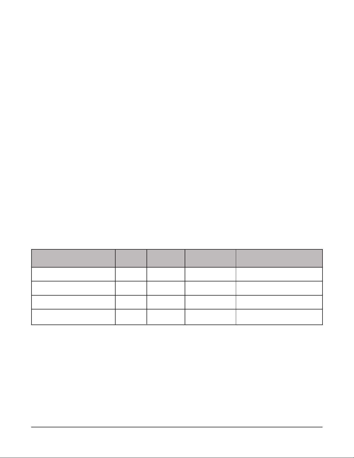
SPECIFICATIONS
No.
Model Size Tubes BTU/Hr. Width Lbs. of Fry Compound
35 3 90,000 15 1/2" (39 cm) 35-40 (16-18 kg)
45 4 120,000 15 1/2" (39 cm) 45-50 (20-23 kg)
65 5 150,000 21" (53 cm) 65-75 (29-34 kg)
85 5 150,000 21" (53 cm) 85-90 (39-41 kg)

– 6 –
OPTIONS AND FEATURES
• Stainless Steel Tank (Standard)
• Basket Lift with Timer (D and C series)
• Tri-, Twin- or Single-Basket (D and C series)
• Manual Pilot or Electronic Ignition (D and C series)
• Filter-Ready (Stand-alone fryers only)
• Filter-In-A-Drawer (Model numbers ending in F)
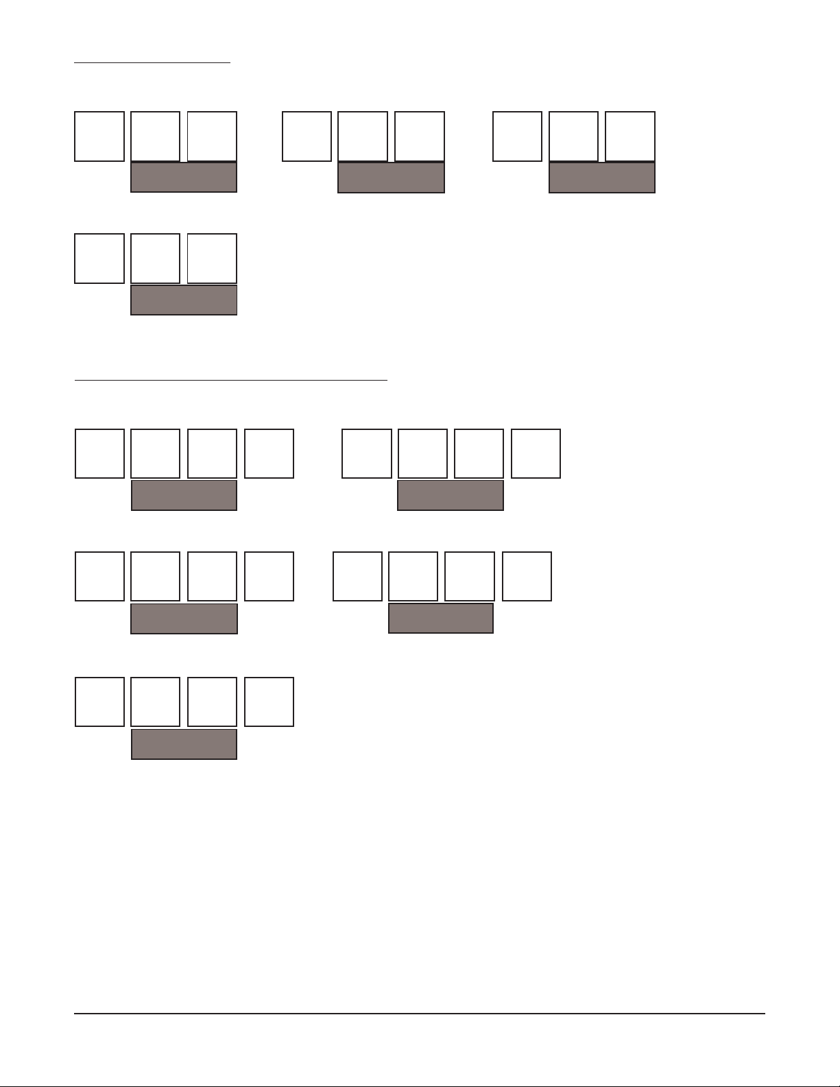
BATTERY CONFIGURATIONS
• Batteries can be configured with any HGF, HGD or HGC Series Fryer or Frymate Dump Station;
only one Frymate Dump Station per battery (Fig. 1).
• All fryers can be free-standing or arranged in batteries of 2 to 4 units.
• The number preceding the model number of your HGF, HGD or HGC Series Fryer refers to the
number of units in a battery.
• All options and accessories can be used in any battery configuration.
• All "F" suffix filter models may be in batteries of 2 to 4.
Non Filter Models
D = Dump Station = Fryer
*Indicates interplumbing is not applicable.
Fig. 1
A
A
A
A
B
BC
BCD
D
D
D
D
D
D
D
D
DD
*
*
Filter
Filter
Filter
AB
AB
A
B
Fryer Fryer Fryer Dump Dump Fryer
Filter-In-A-Drawer Models [HG(F), HGD(F), HGC(F)]
2 Cabinets in Battery
– 7 –
3 Cabinets in Battery
Filter
Filter
Filter
Fryer Fryer Fryer
AB
C
Fryer Dump Fryer
A
BC
Fryer Fryer Dump
AB
C
Filter
A
B
C
Dump Fryer Fryer
4 Cabinets in Battery (For 35 and 45 Only)
ABCD
Filter
Fryer Fryer Fryer Dump
ABCD
Filter
Fryer Dump Fryer Fryer
ABCD
Filter
Fryer Fryer Dump Fryer
ABCD
Filter
Dump Fryer Fryer Fryer
ABCD
Filter
Fryer Fryer Fryer Fryer
The configurations shown are standard (default) locations. Any deviation will result in substantially
increased lead times. Check with your Hobart customer service representative for acceptance of
different configurations.
– 8 –
HGF SERIES FRYMATE (Dump Station)
Model HGFO Frymate Dump Station can be configured in a battery with fryers 15
1
/2" (39 cm) or
21" (53 cm) in width.
Frymate provides a final prep area where excess oil drains away and product is seasoned, packaged
and kept ready for sale.
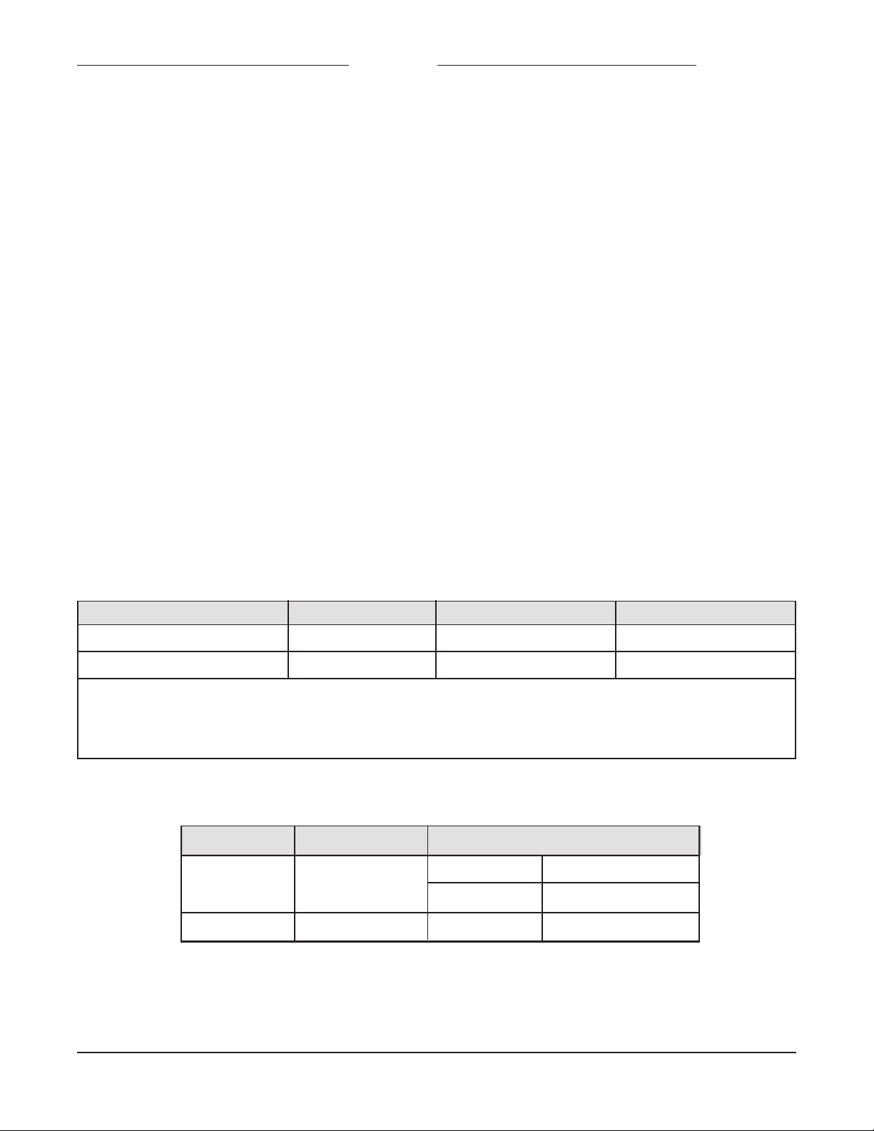
HGFO Series Frymate - Finish Options
HGFO Series Frymate - Features
Sizes Heat Lamp Tops
35 & 45 Opt.
Solid Pan Pan Perforated
Std. N/A
65 & 85 Opt. Std. Opt.
HGFO15, HGFO21, HGFO21S Front Door Sides & Dummy Flue Legs
Standard Stainless Steel Stainless Steel Stainless Steel Legs
Optional N/A N/A Casters
Model HGFO15 is for use with all 35 and 45 Series Fryers.
Model HGFO21 is for use with all 65 Series Fryers.
Model HGFO21S is for use with all 85 Series Fryers.
FACTORY-INSTALLED OPTIONS
• Basket Lift
• Battery Configuration
• Battery Interplumbing (Model numbers
ending in F)
• Electronic Ignition
FIELD-INSTALLED ACCESSORIES
• Casters
• Twin Baskets
• Tri-Baskets (65 and 85 models only)
• Single Baskets
• Heat Lamp (RO only)
• Flex Hose 4' (1.2 m) (gas connection)
• Flex hose S/S 5' (1.5 m) (gas connection)
• Vat Cover
• Battery Tray
• Tank Skimmer
• Tank Scoop
– 9 –
INSTALLATION
Before installing the fryer, verify that the type of gas (natural or propane) agrees with the specifications
on the fryer data plate, which is located on the inside of the door panel. Ensure the fryer is configured
for the proper elevation.
UNPACKING
This fryer was carefully inspected before leaving the factory. The transportation company assumes full
responsibility for safe delivery upon acceptance of the shipment.
Immediately after unpacking the fryer, check for possible shipping damage. If the fryer is damaged,
save the packaging material and contact the carrier within 15 days of delivery.
Do not use the door or its handle to lift the fryer.
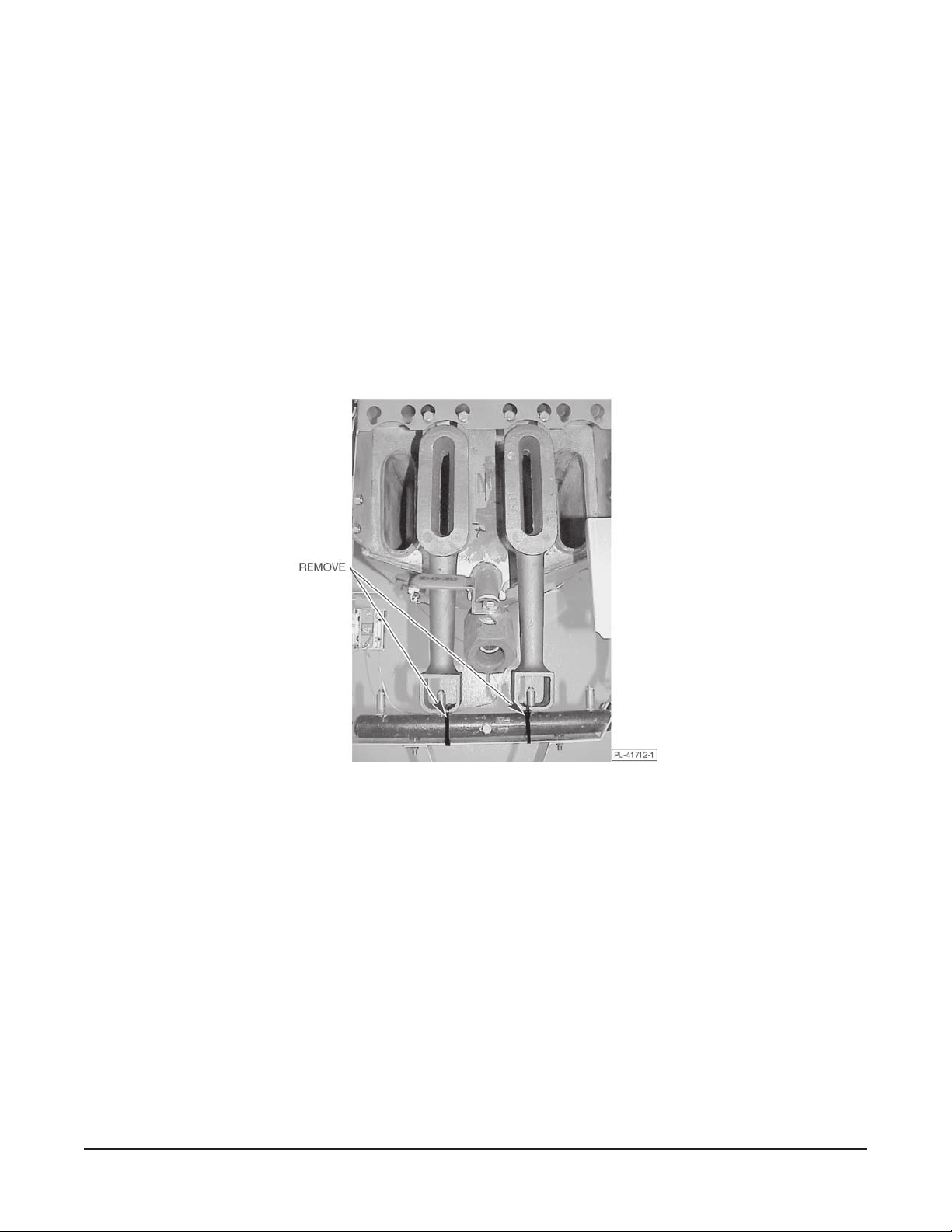
Remove tiedown straps from the burners (Fig. 2).
Fig. 2

– 10 –
LOCATION
The equipment area must be kept free and clear of combustible substances. Minimum clearance from
combustible construction is 6" (15 cm) from the sides and 6" (15 cm) from the back of the fryer.
Minimum clearance from noncombustible construction is 0" from the sides and 0" from the back.
At least 16" (41 cm) clearance must be between the fryer and any open-top flame units. Adequate
clearances for servicing and proper operation must be allowed. The fryer may be installed on
combustible floors.
Install the fryer in an area with sufficient air supply for combustion of the gas at the fryer burners.
Provide adequate clearance for air openings into the combustion chamber. Do not obstruct the flow of
combustion and ventilation air. Do not permit fans to blow directly on the fryer. Avoid wall-type fans
which create cross-currents within a room. Avoid open windows next to the sides or back.
INSTALLATION CODES AND STANDARDS
The fryer must be installed in accordance with:
In the United States of America:
1. State and local codes, or in the absence of local codes, with:
2. National Fuel Gas Code, ANSI-Z223.1 (latest edition), available from The American Gas
Association, Inc., 1515 Wilson Blvd., Arlington, VA 22209.
3. National Electrical Code ANSI/NFPA70 (latest edition) (if applicable).
In Canada:
1. Local codes.
2. CSA Standard C22.2 No. 3 Electrical Features of Fuel Burning Equipment (latest edition).
3. CAN/CGA-B149.1 Natural Fuel Gas Code (latest edition), available from The Canadian Gas
Association, 178 Rexdale Blvd., Etobicoke, Ontario, Canada M9W 1R3.
– 11 –
ASSEMBLY
When installed, the fryer must be restrained to prevent tipping to avoid the splashing of hot liquid. The
means of restraint may be the manner of installation, such as connection to a battery of appliances or
installing the fryer in an alcove, or by separate means, such as adequate ties.
Fryers Mounted on Legs (Non-Batteried Fryers)
Fryers serviced from the rear must have a minimum clearance of 18" (46 cm) from the wall when
mounted on legs.
1. Position fryer in an open space near the final installation area.
2. Tilt fryer on its side. Be careful not to scratch the finish.
3. Thread legs into mounting holes provided on bottom of fryer, then tighten.
4. Carefully raise fryer to its normal position.
Fryers Mounted on Casters
Separate instructions for installing casters to the fryer are included with the casters.
• For an appliance equipped with casters, instructions that (1) the installation shall be made with
a connector that complies with the Standard for
Connectors for Movable Gas Appliances, ANSI
Z21.69
or
Connectors for Moveable Gas Appliances, CAN/CGA-6.16
, and a quick-disconnect
device that complies with the Standard for
Quick-Disconnect Devices for Use With Gas Fuel,
ANSI Z21.41
, or
Quick Disconnect Devices for Use with Gas Fuel, CANI-6.9
, (2) adequate
means must be provided to limit the movement of the appliance.
• The fryer must be installed with a connector (not supplied by Hobart) in compliance with the
above code(s).
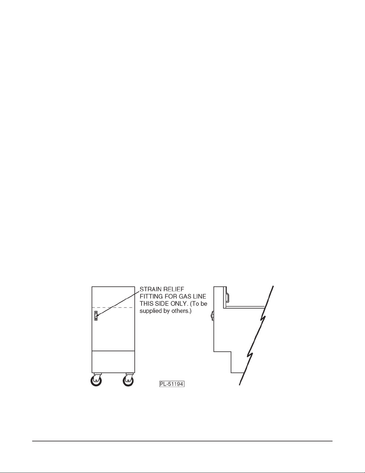
• The fryer must be installed with restraining means to guard against transmission of strain to the
connector, as specified in the strain relief manufacturer's instructions (Fig. 3).
• The fryer must be installed with the casters provided.
• Turn the gas supply off before disconnecting the restraint.
Fig. 3
REAR
Loading...