


|
|
|
ENGLISH |
|
|
|
ENGLISH |
||
|
|
|
||
|
|
|
|
|
|
|
|
|
|
TIME LAPSE
VIDEO CASSETTE RECORDER
VTL4024E
Instruction manual
To obtain the best performance and ensure years of trouble-free use, please read this instruction manual completely.
Bedienungsanleitung
Bitte lesen Sie diese Bedienungsanleitung aufmerksam durch, um durch richtige Bedienung jahrelangen und störungsfreien Betrieb zu gewährleisten.
Mode d’emploi
Des performances optimales et un fonctionnement à long terme seront assurés en appliquant les présentes instructions après avoir entièrement lu ce mode d’emploi.
Manuale di istruzioni
Per garantire la migliore prestazione e la più lunga durata leggere attentamente e al completo le seguenti istruzioni.
Manual de instrucciones
Para obtener el mejor funcionamiento y asegurar años de uso libre de problemas, lea cuidadosamente este manual de instrucciones.
Gebruiksaanwijzing
Lees deze gebruiksaanwijzing aandachtig door voor het verkrijgen van de beste prestaties en jarenlang probleemloos gebruik.

ENGLISH
WARNING
•Main supply:
AC 230V, 50 Hz only
•Do not remove panel covers by unscrewing them. There are no user-serviceable parts inside. Refer all servicing to qualified service personnel.
•To prevent fire or shock hazard, do not expose this unit to rain or moisture.
PRECAUTIONS
Safety
•Should any solid object or liquid fall into the cabinet, turn off the unit and have it checked by qualified personnel before operating it any further.
•To disconnect the mains lead, pull it out by the plug. Never pull the lead itself.
Installation
•Choose a location in which air can pass through the ventilation holes in the bottom, top and back of the unit to prevent it from overheating.
•Do not install the unit near heat sources such as radiators or air ducts or in a place subject to direct sunlight, excessive dust, mechanical vibrations or shock.
•Do not place heavy objects or heat-generating objects on the VCR, or the cabinet could be damaged or the temperature inside the VCR could rise, which could cause a fault.
•Never bring a magnet or magnetized object near the VCR because it will adversely affect the performance of the VCR.
•Do not install the unit in an inclined position. The unit is designed for operation in a horizontal position.
•Do not place a container with water or any small metal objects on the VCR: If spilled water or a metal object, such as paper clip, enters the VCR, it could cause a fire or electric shock.
Operation
•Condensation
If you pour a cold liquid into a glass, water vapor in the air will condense on the surface of the glass.
This is the condensation of moisture. Condensation on the head drum, one of the most crucial parts of the VCR, will cause damage to the tape. The VCR should not be operated for at least 2 hours after being moved from a cold to a hot environment to avoid condensation from occurring on the head drum.
Cleaning
•Be careful; when the surface of the case is wiped with a volatile agent such as benzine, alcohol, thinner, etc., or a chemically processed cloth, the surface finish may be degraded or its coating may peel off.
Repacking
•It is wise to save the packing materials and box in case you ever need to ship or store your unit.
1
FEATURES |
|
CONTENTS |
Recording
•Three Touch-Selectable Recording Speeds (03, 12, 24)
•Recording Check
•Auto Recording Check
•On-Screen and On-Tape Time/Date Information
•7-Day Programmable On/Off Timer
•“Alarm On” Output
•Usable Audio at 03, A12 and A24 hour Speeds
Playback
•Time-of-Alarm Memory and Alarm Index Search
•High Speed Visual Search
•Four Playback Speeds (03, A12, A24, 24)
•Still Field, Field-Advance, Field-Reverse and Reverse Playback
Security
•About 720 hours Memory Protection
•Electronic Security Lockout
•Buzzer Function
Note: This recorder has a rechargeable battery to maintain display functions and recording mode within 720 hours in the event of power loss. When the recorder is received, the unit must be connected to power source for 48 hours to assure the battery has been adequately charged.
CONTROLS AND FUNCTIONS .................................. |
3 |
INSTALLATION ........................................................... |
7 |
EXTERNAL CONNECTIONS....................................... |
8 |
CASSETTE TAPES .................................................... |
10 |
SETUP ........................................................................ |
11 |
SETTING THE TIME AND DATE .......................... |
12 |
SETTING [OPTIONS] ITEMS................................ |
13 |
SUMMER TIME FUNCTION ................................. |
13 |
SETTING THE TIMER............................................ |
13 |
SETTING THE VCR FUNCTIONS ......................... |
15 |
SETTING THE BUZZER......................................... |
16 |
SETTING THE ALARM.......................................... |
17 |
ALARM MEMORY RECALL AND RESET ............ |
18 |
OPERATION............................................................... |
19 |
TAPE RECORDING................................................ |
19 |
REC CHECK............................................................ |
19 |
AUTO REC CHECK ................................................ |
19 |
TIMER RECORDING.............................................. |
19 |
TAPE RECYCLE ..................................................... |
19 |
ALARM RECORDING ............................................ |
20 |
MASTER SYSTEM RESET.................................... |
20 |
PLAYBACK............................................................. |
20 |
SHARPNESS CONTROL....................................... |
20 |
STILL PLAYBACK.................................................. |
20 |
V.LOCK ADJUST................................................... |
20 |
PLAYBACK IN THE FIELD ADVANCE/ |
|
REVERSE MODES ............................................ |
20 |
VISUAL SEARCH (High Speed Scan) ................. |
21 |
ALARM INDEX SEARCH ...................................... |
21 |
TO SECURE THE VCR .......................................... |
21 |
PROBLEM GUIDE...................................................... |
22 |
SPECIFICATIONS ...................................................... |
23 |
MAINTENANCE/INSPECTION SCHEDULES OF |
|
MECHANICAL COMPONENTS ............................ |
24 |
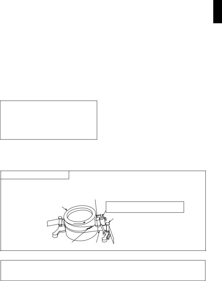
Auto Head Cleaning System
This system cleans the video heads automatically when a cassette is inserted and ejected or the tape is rewound in the recycle recording mode, to prevent dirt from accumulating on the heads.
Touches the video head in the active position
Cylinder |
Cleaning roller in the stand-by position |
|
(Special material) |
|
Tape guide |
ENGLISH
Video |
Tape |
REC CHECK before starting
In order to prevent the misrecording, press the PLAY button during recording. See page 19.
2
|
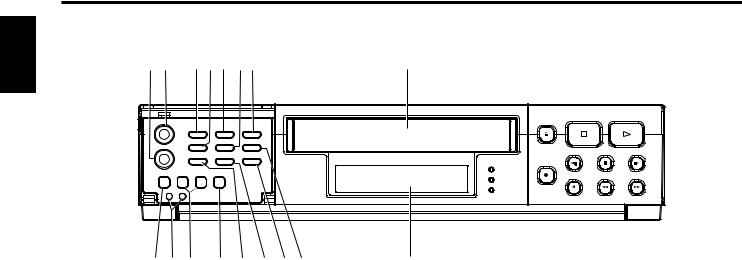
CONTROLS AND FUNCTIONS |
|
||||
ENGLISH |
[FRONT] |
|
|
|
|
|
1 |
2 |
3 |
4 5 6 7 |
8 |
||
|
||||||
|
|
|
S |
|
|
|
|
9 |
1011 |
12 13 14 1516 |
DISPLAY (See page 5) |
||
1.SLOW TRACKING CONTROL
Adjust to optimize the picture quality in the SLOW PLAY mode, e.g. 24 hours speed.
2.TRACKING CONTROL
Adjust to optimize the picture quality during playback at the 03, A12 and A24 hour speeds.
3.PROG./SHARPNESS CONTROL
Press to select one of the seven programmable functions.
Press to select the picture quality with the UP/HARD or DOWN/SOFT button to hard or soft during playback. See page 20 for SHARPNESS CONTROL.
4.DOWN/SOFT BUTTON
Press to decrement, change or reverse to the previous/lower value.
Press to adjust the picture quality to soft during playback.
5.START/STOP BUTTON
Press to start or stop the programming of a programmable function. (Press once to start the programming sequence and a second time to stop (end) it.)
6.UP/HARD BUTTON
Press to increase, change or advance to the next higher value.
Press to adjust the picture quality to hard during playback.
7.SET BUTTON
Press to select the specific value which is to be changed with the UP/DOWN buttons.
8.CASSETTE COMPARTMENT
9.COUNTER RESET BUTTON
Press to clear the digital counter to “0000”.
10.RESET BUTTONS
Press these buttons at the same time to clear all (microprocessor) functions.
Press the “S” button to reset the system. (This does not erase the stored information.)
11.REC/PLAY HOURS BUTTONS
▲ (UP): |
Press to increase hours to the next |
|
higher value. |
▼ (DOWN): Press to decrease hours to the next lower value. The tape speed will be indicated as part of the monitor display.
12.TIMER BUTTON
Press after programming the TIMER for automatic TIMER recording. See page 13 for TIMER programming.
13.V-POS (VERTICAL POSITION) / V-LOCK BUTTON
Press repeatedly to control the vertical position of the programmable display on the monitor.
Press to reduce vertical jitter in the still play mode.
14.H-POS (HORIZONTAL POSITION) / V-LOCK BUTTON
Press repeatedly to control the horizontal position of the programmable display on the monitor.
Press to reduce vertical jitter in the still play mode.
15.ALARM RESET BUTTON
Press to clear POWER LOSS information. When this button is pressed when the Alarm Memory screen is being displayed, the alarm memory is cleared.
16.ALARM INDEX BUTTON
Press this button to cause the INDEX indicator to light, and set the VCR to the visual search mode (press F.FWD or REWIND during playback mode) in this state; the start of the alarm recorded can be located.
3
|
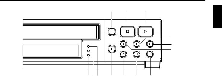
17 |
18 |
|
19 |
ENGLISH |
|
|
|
|
|
|
|
|
|
|
|
29 |
|
|
|
|
|
28 |
|
|
|
|
|
27 |
20 21 22 |
23 |
24 |
25 |
26 |
|
17.EJECT BUTTON
Press to remove the cassette. The EJECT button will not operate in the RECORD mode.
18.STOP BUTTON
Press to stop the tape. The STOP button must be pressed to end the RECORD and PLAY mode.
19.PLAY BUTTON
Press to play recorded material in the forward direction. Pressing this during recording makes it possible to check recordings.
20.TIMER LED
The LED lights up during timer recording or timer stand by mode.
21.ALARM LED
The LED lights up during alarm recording.
22.REC LED
The LED lights up during recording.
23.RECORD BUTTON
Press to start recording.
24.REVERSE PLAY BUTTON
25.REWIND/VISUAL SEARCH BUTTON
Press to start rewind.
Press this button during playback and a reverse playback picture at high speed can be seen.
26.FAST FORWARD/VISUAL SEARCH BUTTON
Press to activate fast forward.
Press this button during playback and a forward playback picture at high speed can be seen.
27.FIELD REVERSE BUTTON
Press to reverse the tape by one field in the STILL playback mode.
28.FIELD ADVANCE BUTTON
Press to advance the tape one field in the STILL playback mode.
29.STILL BUTTON
Press to momentarily stop tape motion in the play mode. The STILL function allows close inspection of individual scenes. See the description of STILL playback on page 20.
Press to play recorded material at the 03 speed in the reverse direction during the PLAY mode.
4
ENGLISH
CONTROLS AND FUNCTIONS (Continued)
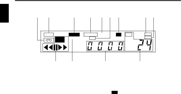
[DISPLAY]
30 |
31 |
32 |
33 |
34 |
35 |
36 |
37 |
38 |
T A B |
|
ALARM |
TAPE END |
A |
LOCK |
SPEED |
HARD |
|
REC |
INDEX |
TIMER |
|
|
|
SOFT |
|
|
|
|
|
|
|
39 |
40 |
41 |
42 |
30.TAPE-IN INDICATOR
Lights when a cassette is in the compartment.
31.TAB INDICATOR
Lights when a cassette without its safety tab is loaded.
32.ALARM INDICATOR
ALARM appears during alarm recording. ALARM flashes when alarm recording ends.
33.TAPE END INDICATOR
Lights when the tape reaches the end during recording.
Note: “TAPE END” is not displayed when you have selected REWIND, RE-REC in the “RECYCLE FUNCTIONS” menu in the alarm display or you have selected REWIND, STOP IF ALARM but an alarm recording has not been made.
34.A INDICATOR
Lights when no video signal is input. Video signal input will turn this indicator off automatically.
35.TIMER INDICATOR
This is lit during timer recording or TIMER stand-by mode.
The indicator flashes in the following cases.
•A cassette is not loaded.
•A cassette without its safety tab is loaded.
•The timer has not been programmed.
36.LOCK INDICATOR
LOCK appears when the recorder is in the security lock mode.
37.HARD INDICATOR
Lights when adjust the picture quality to hard during playback mode and after setting.
38.SOFT INDICATOR
Lights when adjust the picture quality to soft during playback mode and after setting.
39.VCR MODE INDICATORS
•REC appears during recording.
•tt appears during the rewind mode.
•ss appears during the fast forward mode.
•tt (or ss) flashes during visual search.
•s appears during the playback mode.
•t appears during the reverse play mode.
•appears when the STILL button is pressed during play mode and disappears when the STILL or PLAY button is pressed again.
•t (or s) appears while the FIELD REV (or FIELD ADV) is held depressed in the still playback mode.
Note: Still playback is restored when the FIELD REV (or FIELD ADV) button is released.
40.INDEX INDICATOR
INDEX appears when the ALARM INDEX button is pressed.
INDEX disappears when the ALARM INDEX button is pressed again.
INDEX flashes during alarm indexing.
41.DIGITAL COUNTER
Shows the tape counter. The counter does not count during non-recorded sections of a tape.
In low temperature, display speed may be slow. The count of a counter is ensured.
42.TAPE SPEED INDICATOR
Shows the tape speed.
5

[REAR] |
44 45 |
ENGLISH |
43 |
|
46 |
47 |
48 |
43.AC INLET
44.VIDEO IN
Receives video signal from a video camera or another VCR.
45.VIDEO OUT
For connection to monitor.
46.EXTERNAL INTERFACE (8 X 2-PIN) JACK
Connect an alarm switch, door sensor, etc.
47.AUDIO IN
Accepts an audio signal from a camera, external sound equipment or another recorder (Line: –8 dBm, 50 kohm, unbalanced).
48.AUDIO OUT
Provides an audio output for a monitor or another recorder (–9 dBm, 600 ohm, unbalanced).
1 |
2 |
3 |
4 |
5 |
6 |
7 |
8 |
9 |
10 11 12 13 14 |
15 16 |
CONNECTING WIRES
1.Strip off the wire cover by approx. 10mm.
2.Use a screwdriver, etc. to hold the tab, then insert the wire.
•Push the tab firmly when inserting wire.
3.Release the screwdriver.
•The wire will be fixed.
Note: When disconnecting the wire, use the screwdriver again to hold the tab, then pull the wire out.
q ALARM IN w ALARM OUT e NC
r TAPE END OUT t TAPE END RESET y WARNING OUT u NC
i TIME ADJUST
o CAMERA SW OUT !0REC START IN
!1NC
!2NC
!3REMOTE IN !4REC CHECK IN !5GND
!6GND
Tab Screwdriver
Wire
10mm
6
ENGLISH
INSTALLATION
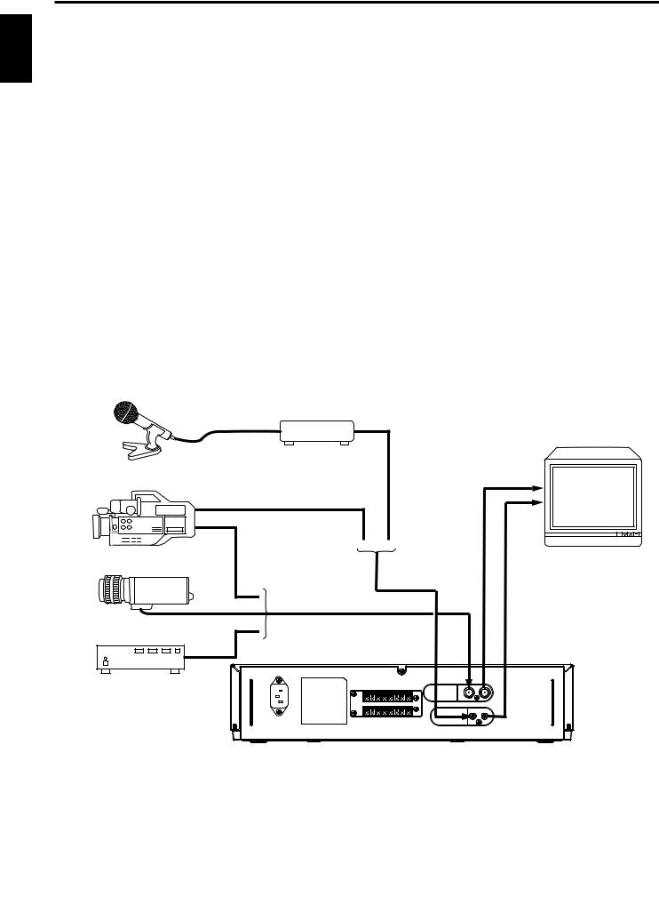
VIDEO CONNECTIONS
Use coaxial cables when connecting a camera and a monitor to this VCR.
Note: Long cable runs to distant cameras may cause signal deterioration and/or sync discrepancies. If these problems occur, use video line amplifiers and/or cameras having phase-adjustable line-locked vertical sync.
Video Input
In single camera systems, connect the camera to the Video IN BNC terminal on the VCR rear panel. Use of a 2:1 interlace camera is highly recommended; otherwise, the monitor will show vertical distortion of the TIME/DATE characters.
In multiple camera systems, connect the switcher output to the Video IN BNC terminal. Because multiple camera systems require synchronization, use of cameras having line-locked vertical sync or a genlocked master drive/sync source is highly recommended. The use of vertical interval switchers is also recommended.
Video Output
Connect the monitor to the Video OUT BNC terminal on the rear panel.
AUDIO CONNECTIONS
Note: Audio recording can be performed at the 03, 12 and 24-hour recording speeds and audio playback at the 03, A12, and A24 speeds.
Audio In: Accepts an audio signal from a camera, external sound equipment, or another recorder (Line: –8 dBm, 50 kohm).
Audio Out: Provides an audio output for a monitor or another recorder (–9 dBm, 600 ohm, unbalanced).
MICROPHONE |
PREAMP |
|
|
|
MONITOR |
VIDEO CAMERA/RECORDER |
|
CAMERA |
|
SWITCHER |
|
7 |
|

EXTERNAL CONNECTIONS
ALARM IN
You can connect an alarm switch with a resistance of 1 kohm or less or a door sensor. Connect pin q to !5or !6(ground) through the switches.
ALARM IN |
GND |
|
1 |
1 |
|
15 or |
6 |
|
Note: Do not apply a voltage to pin q , !5or !6.
ALARM OUT
Approx. 12V is applied to pin w during an alarm recording.
Notes:
•When you have selected “PULSE” in the “ALARM OUT” menu in the ALARM display, approx. 12V pulses will be applied to the output after the alarm recording ends.
•When you have selected “DURATION” in the “ALARM OUT” menu in the ALARM display, no voltage is applied after the alarm recording ends.
•The output impedance is approx. 100 ohm.
TAPE END OUT
Approx. 12V is applied to pin r when the tape reaches the end.
Notes:
•This does not operate when you have selected “REW, RE-REC” in the “RECYCLE FUNCTIONS” menu in the ALARM display or you have selected “REWIND, STOP IF ALARM” and no alarm recording has been made.
•The output impedance is approx. 100 ohm.
TAPE END RESET
The TAPE END OUT can be turned off when pin t is shorted to pin !5or !6.
Note: Do not apply a voltage to pin t , !5or !6.
WARNING OUT
When an abnormality has occurred in this VCR, approx. 5V is output to pin y to warn the user.
TIME ADJUST
When two or more of this VCR model are used, connect via these terminals. With only one VCR, specify TIME ADJUST: MASTER, in [OPTIONS] items on the CLOCK SET display. Specify TIME ADJUST: SLAVE (default setting at the factory) for all other VCRs. Each time “2:00:05” is reached, the VCR set to MASTER transmits pulses for adjustment to the VCRs set to SLAVE. When the VCRs set to SLAVE receive these pulses, their clocks will adjust to the same time as the clock in the VCR set to MASTER.
Notes:
•Do not connect any device to pin e , u , !1, !2.
•Be sure to set only one VCR to MASTER. If no VCR is set to MASTER, or two or more VCRs are set to MASTER, the TIME ADJUST function will not operate normally.
ENGLISH
8
 Loading...