


SJ300 Series Inverter
Instruction Manual
• Three-phase Input |
200V Class |
• Three-phase Input |
400V Class |
U.S. Version Models |
European Version Models |
Manual Number: NB613XJ |
After reading this manual, |
September 2006 |
keep it handy for future reference. |
|
|
Hitachi Industrial Equipment Systems Co., Ltd.
i
SJ300 Inverter
Safety Messages
Definitions and
Symbols
For the best results with the SJ300 Series inverter, carefully read this manual and all of the warning labels attached to the inverter before installing and operating it, and follow the instructions exactly. Keep this manual handy for quick reference.
A safety instruction (message) includes a hazard alert symbol and a signal word, WARNING or CAUTION. Each signal word has the following meaning:
This symbol indicates HIGH VOLTAGE. It calls your attention to items or operations that could be dangerous to you and other persons operation this equipment. Read the message and follow the instructions carefully.
This symbol is the “Safety Alert Symbol.” It occurs with either of two signal words: CAUTION or WARNING, as described below.
WARNING: Indicates a potentially hazardous situation that, if not avoided, can result in serious injury or death.
CAUTION: Indicates a potentially hazardous situation that, if not avoided, can result in minor to moderate injury, or serious damage to the product. The situation described in the CAUTION may, if not avoided, lead to serious results. Important safety measures are described in CAUTION (as well as WARNING), so be sure to observe them.
STEP: A step is one of a series of action steps required to accomplish a goal. The 
 number of the step will be contained in the step symbol.
NOTE: Notes indicate an area or subject of special merit, emphasizing either the product’s capabilities or common errors in operation or maintenance.
TIP: Tips give a special instruction that can save time or provide other benefits while installing or using the product. The tip calls attention to an idea that may not be obvious to first-time users of the product.
Hazardous High Voltage
HIGH VOLTAGE: Motor control equipment and electronic controllers are connected to hazardous line voltages. When servicing drives and electronic controllers, there may be exposed components with housings or protrusions at or above line potential. Extreme care should be taken to protect against shock.
Stand on an insulating pad and make it a habit to use only one hand when checking components. Always work with another person in case an emergency occurs. Disconnect power before checking controllers or performing maintenance. Be sure equipment is properly grounded. Wear safety glasses whenever working on electronic controllers or rotating machinery.
ii
General Precautions - Read These First!
WARNING: This equipment should be installed, adjusted, and serviced by qualified electrical maintenance personnel familiar with the construction and operation of the equipment and the hazards involved. Failure to observe this precaution could result in bodily injury.
WARNING: The user is responsible for ensuring that all driven machinery, drive train mechanism not supplied by Hitachi Industrial Equipment Systems Co., Ltd., and process line material are capable of safe operation at an applied frequency of 150% of the maximum selected frequency range to the AC motor. Failure to do so can result in destruction of equipment and injury to personnel should a single-point failure occur.
WARNING: For equipment protection, install a ground leakage type breaker with a fast response circuit capable of handling large currents. The ground fault protection circuit is not designed to protect against personal injury.
HIGH VOLTAGE: HAZARD OF ELECTRICAL SHOCK. DISCONNECT INCOMING
POWER BEFORE WORKING ON THIS CONTROL.
WARNING: Wait at least five (5) minutes after turning OFF the input power supply before performing maintenance or an inspection. Otherwise, there is the danger of electric shock.
CAUTION: These instructions should be read and clearly understood before working on
SJ300 series equipment.
CAUTION: Proper grounds, disconnecting devices and other safety devices and their location are the responsibility of the user and are not provided by Hitachi Industrial Equipment Systems Co., Ltd.
CAUTION: Be sure to connect a motor thermal disconnect switch or overload device to the SJ300 series controller to assure that the inverter will shut down in the event of an overload or an overheated motor.
HIGH VOLTAGE: Dangerous voltage exists until power light is OFF. Wait at least 5 minutes after input power is disconnected before performing maintenance.
CAUTION: This equipment has high leakage current and must be permanently (fixed) hardwired to earth ground via two independent cables.
WARNING: Rotating shafts and above-ground electrical potentials can be hazardous. Therefore, it is strongly recommended that all electrical work conform to the National Electrical Codes and local regulations. Installation, alignment and maintenance should be performed only by qualified personnel.
Factory-recommended test procedures included in the instruction manual should be followed. Always disconnect electrical power before working on the unit.
iii
SJ300 Inverter
CAUTION:
a)Motor must be connected to protective ground via low resistive path (< 0.1Ω)
b)Any motor used must be of a suitable rating.
c)Motors may have hazardous moving parts. In this event suitable protection must be provided.
CAUTION: Alarm connection may contain hazardous live voltage even when inverter is disconnected. When removing the front cover for maintenance or inspection, confirm that incoming power for alarm connection is completely disconnected.
CAUTION: Hazardous (main) terminals for any interconnection (motor, contact breaker, filter, etc.) must be inaccessible in the final installation.
CAUTION: The end application must be in accordance with BS EN60204-1. Refer to the section “Step-by-Step Basic Installation” on page 2–6. The diagram dimensions are to be suitably amended for your application.
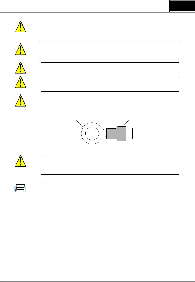
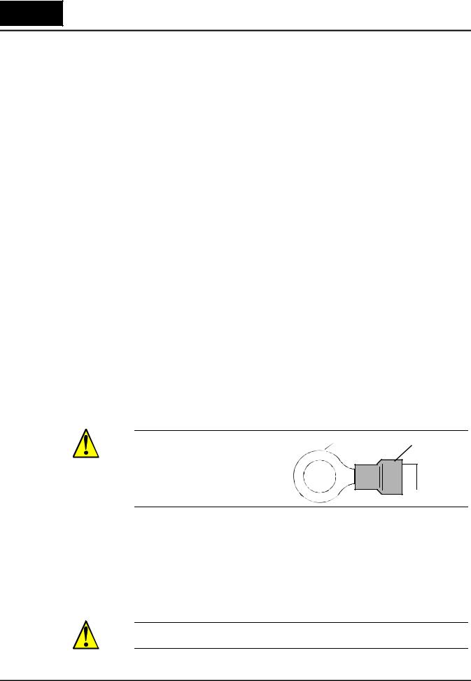
CAUTION: Connection to field wiring terminals must be reliably fixed having two independent means of mechanical support. Using a termination with cable support (figure below), or strain relief, cable clamp, etc.
Terminal (ring lug) |
Cable support |

 Cable
Cable
CAUTION: A three-pole disconnection device must be fitted to the incoming main power supply close to the inverter. Additionally, a protection device meeting IEC947-1/IEC947-3 must be fitted at this point (protection device data shown in “Determining Wire and Fuse Sizes” on page 2–14).
NOTE: The above instructions, together with any other requirements are highlighted in this manual, and must be followed for continued LVD (European Low Voltage Directive) compliance.

iv
Index to Warnings and Cautions in This Manual
Installation—Cautions for Mounting Procedures
CAUTION: Be sure to install the unit on flame-resistant material such as a |
............... 2–6 |
steel plate. Otherwise, there is the danger of fire. |
|
CAUTION: Be sure not to place any flammable materials near the inverter. |
............... 2–6 |
Otherwise, there is the danger of fire. |
|
CAUTION: Be sure not to let the foreign matter enter vent openings in the |
............... 2–6 |
inverter housing, such as wire clippings, spatter from welding, metal |
|
shavings, dust, etc. Otherwise, there is the danger of fire. |
|
CAUTION: Be sure to install the inverter in a place that can bear the weight |
............... 2–6 |
according to the specifications in the text (Chapter 1, Specifications Tables). |
|
Otherwise, it may fall and cause injury to personnel. |
|
CAUTION: Be sure to install the unit on a perpendicular wall that is not |
............... 2–6 |
subject to vibration. Otherwise, it may fall and cause injury to personnel. |
|
CAUTION: Be sure not to install or operate an inverter that is damaged or |
............... 2–6 |
has missing parts. Otherwise, it may cause injury to personnel. |
|
CAUTION: Be sure to install the inverter in a well-ventilated room that |
............... 2–6 |
does not have direct exposure to sunlight, a tendency for high temperature, |
|
high humidity or dew condensation, high levels of dust, corrosive gas, |
|
explosive gas, inflammable gas, grinding-fluid mist, salt air, etc. Otherwise, |
|
there is the danger of fire. |
|
CAUTION: Be sure to maintain the specified clearance area around the |
............... 2–7 |
inverter and to provide adequate ventilation. Otherwise, the inverter may |
|
overheat and cause equipment damage or fire. |
|
Wiring—Warnings for Electrical Practices and Wire Specifications
|
|
WARNING: “Use 60/75°C Cu wire only” or equivalent. |
............. 2–13 |
|
|
WARNING: “Open Type Equipment.” For models SJ300–750H to SJ300– |
2–13 |
|
|
||
|
|
1500H. |
|
|
|
WARNING: “A Class 2 circuit wired with Class 1 wire” or equivalent. |
............. 2–13 |
|
|
||
|
|
WARNING: “Suitable for use on a circuit capable of delivering not more |
2–13 |
|
|
||
|
|
than 100,000 rms symmetrical amperes, 240 V maximum.” For models with |
|
|
|
suffix L. |
|
|
|
WARNING: “Suitable for use on a circuit capable of delivering not more |
............. 2–13 |
|
|
than 100,000 rms symmetrical amperes, 480 V maximum.” For models with |
|
|
|
suffix H. |
|
|
|
|
|
v
SJ300 Inverter
HIGH VOLTAGE: Be sure to ground the unit. Otherwise, there is a danger ............. |
2–13 |
of electric shock and/or fire. |
|
HIGH VOLTAGE: Wiring work shall be carried out only by qualified ............. |
2–13 |
personnel. Otherwise, there is a danger of electric shock and/or fire. |
|
HIGH VOLTAGE: Implement wiring after checking that the power supply ............. |
2–13 |
is OFF. Otherwise, you may incur electric shock and/or fire. |
|
HIGH VOLTAGE: Do not connect wiring to an inverter or operate an ............. |
2–13 |
inverter that is not mounted according the instructions given in this manual. |
|
Otherwise, there is a danger of electric shock and/or injury to personnel. |
|
Wiring—Cautions for Electrical Practices
CAUTION: Be sure that the input voltage matches the inverter specifica- ............. |
2–19 |
tions: • Three phase 200 to 240V 50/60Hz • Three phase 380 to 480V 50/ |
|
60Hz |
|
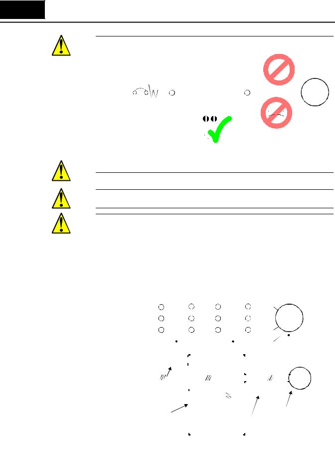
CAUTION: Be sure not to power a three-phase-only inverter with single ............. |
2–19 |
phase power. Otherwise, there is the possibility of damage to the inverter |
|
and the danger of fire. |
|
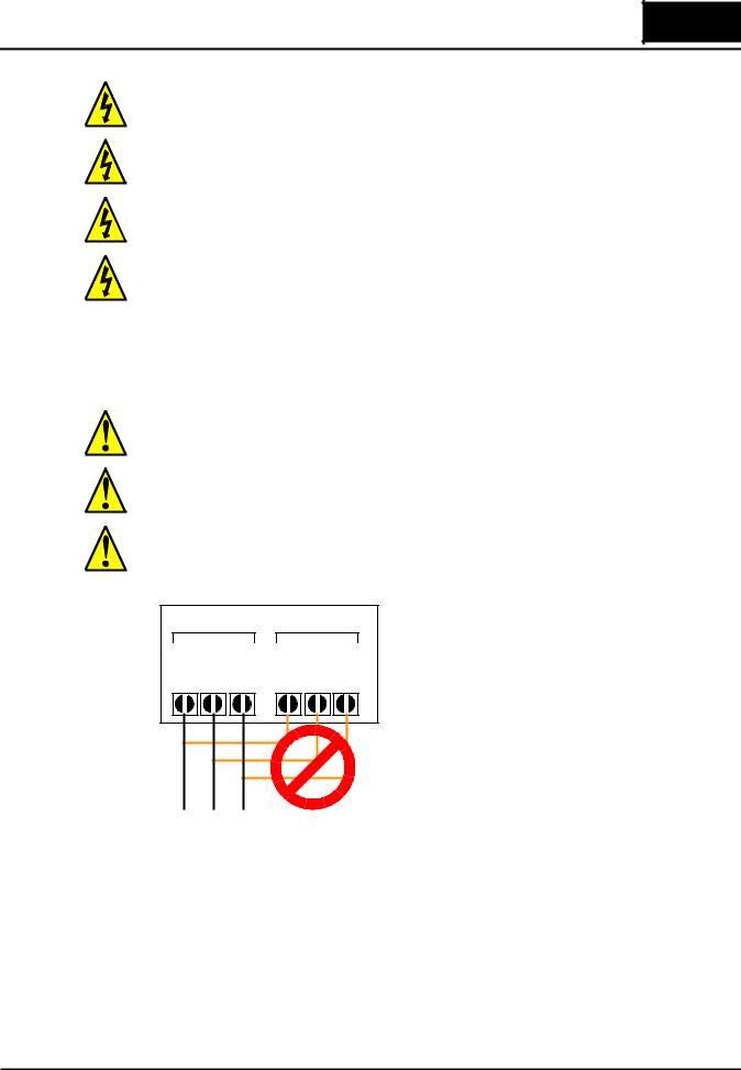
CAUTION: Be sure not to connect an AC power supply to the output termi- ............. |
2–19 |
nals. Otherwise, there is the possibility of damage to the inverter and the |
|
danger of injury and/or fire. |
|
Power Input |
Power Output |
NOTE: |
|
||||
|
|
||||||
L1 |
L2 |
L3 |
T1 |
T2 |
T3 |
L1, L2, L3: |
Three-phase 200 to 240V 50/60 Hz |
|
Three-phase 380 to 480V 50/60 Hz |
||||||
R |
S |
T |
U |
V |
W |
|
|
vi
CAUTION: Fasten the screws with the specified fastening torque in the |
............. 2–16 |
table below. Check for any loosening of screws. Otherwise, there is the |
|
danger of fire. |
|
CAUTION: Remarks for using ground fault interrupter breakers in the main |
............. 2–19 |
power supply: Adjustable frequency inverters with CE-filters (RFI-filter) |
|
and shielded (screened) motor cables have a higher leakage current toward |
|
Earth GND. Especially at the moment of switching ON this can cause an |
|
inadvertent trip of ground fault interrupter breakers. Because of the rectifier |
|
on the input side of the inverter there is the possibility to stall the switch-off |
|
function through small amounts of DC current. Please observe the follow- |
|
ing: • Use only short time-invariant and pulse current-sensitive ground fault |
|
interrupter breakers with higher trigger current. • Other components should |
|
be secured with separate ground fault interrupter breakers. • Ground fault |
|
interrupter breakers in the power input wiring of an inverter are not an |
|
absolute protection against electric shock. |
|
CAUTION: Be sure to install a fuse in each phase of the main power supply |
............. 2–19 |
to the inverter. Otherwise, there is the danger of fire. |
|
CAUTION: For motor leads, ground fault interrupter breakers and electro- |
............. 2–19 |
magnetic contactors, be sure to size these components properly (each must |
|
have the capacity for rated current and voltage). Otherwise, there is the |
|
danger of fire. |
|
CAUTION: Failure to remove all vent opening covers before electrical |
............. 2–20 |
operation may result in damage to the inverter. |
|
Powerup Test Caution Messages
CAUTION: The heat sink fins will have a high temperature. Be careful not |
............. 2–21 |
to touch them. Otherwise, there is the danger of getting burned. |
|
CAUTION: The operation of the inverter can be easily changed from low |
............. 2–21 |
speed to high speed. Be sure to check the capability and limitations of the |
|
motor and machine before operating the inverter. Otherwise, there is the |
|
danger of injury. |
|
CAUTION: If you operate a motor at a frequency higher than the inverter |
............. 2–22 |
standard default setting (50Hz/60Hz), be sure to check the motor and |
|
machine specifications with the respective manufacturer. Only operate the |
|
motor at elevated frequencies after getting their approval. Otherwise, there |
|
is the danger of equipment damage and/or injury to personnel. |
|
CAUTION: Check the following before and during the powerup test. Other- |
............. 2–22 |
wise, there is the danger of equipment damage. • Is the shorting bar between |
|
the [P] and [PD] terminals installed? DO NOT power or operate the inverter |
|
if the jumper is removed. • Is the direction of the motor rotation correct? • Did the inverter trip during acceleration or deceleration? • Were the rpm and frequency meter readings as expected? • Were there any abnormal motor vibrations or noise?

vii
SJ300 Inverter
Warnings for Operations and Monitoring
WARNING: Be sure to turn ON the input power supply only after closing |
............... 4–3 |
the front case. While the inverter is energized, be sure not to open the front |
|
case. Otherwise, there is the danger of electric shock. |
|
WARNING: Be sure not to operate electrical equipment with wet hands. |
............... 4–3 |
Otherwise, there is the danger of electric shock. |
|
WARNING: While the inverter is energized, be sure not to touch the |
............... 4–3 |
inverter terminals even when the motor is stopped. Otherwise, there is the |
|
danger of electric shock. |
|
WARNING: If the Retry Mode is selected, the motor may suddenly restart |
............... 4–3 |
after a trip stop. Be sure to stop the inverter before approaching the machine |
|
(be sure to design the machine so that safety for personnel is secure even if |
|
it restarts.) Otherwise, it may cause injury to personnel. |
|
WARNING: If the power supply is cut OFF for a short period of time, the |
............... 4–3 |
inverter may restart operation after the power supply recovers if the Run |
|
command is active. If a restart may pose danger to personnel, so be sure to |
|
use a lock-out circuit so that it will not restart after power recovery. Other- |
|
wise, it may cause injury to personnel. |
|
WARNING: The Stop Key is effective only when the Stop function is |
............... 4–3 |
enabled. Be sure to enable the Stop Key separately from the emergency |
|
stop. Otherwise, it may cause injury to personnel. |
|
WARNING: During a trip event, if the alarm reset is applied and the Run |
............... 4–3 |
command is present, the inverter will automatically restart. Be sure to apply |
|
the alarm reset only after verifying the Run command is OFF. Otherwise, it |
|
may cause injury to personnel. |
|
WARNING: Be sure not to touch the inside of the energized inverter or to |
............... 4–3 |
put any conductive object into it. Otherwise, there is a danger of electric |
|
shock and/or fire. |
|
WARNING: If power is turned ON when the Run command is already |
............... 4–3 |
active, the motor will automatically start and injury may result. Before |
|
turning ON the power, confirm that the RUN command is not present. |
|
WARNING: When the Stop key function is disabled, pressing the Stop key |
............... 4–3 |
does not stop the inverter, nor will it reset a trip alarm. |
|
WARNING: Be sure to provide a separate, hard-wired emergency stop |
............... 4–3 |
switch when the application warrants it. |
|
WARNING: If the power is turned ON and the Run command is already |
............. 4–12 |
active, the motor starts rotation and is dangerous! Before turning power ON, |
|
confirm that the external Run command is not active. |
|
WARNING: After the Reset command is given and the alarm reset occurs, |
............. 4–27 |
the motor will restart suddenly if the Run command is already active. Be |
|
sure to set the alarm reset after verifying that the Run command is OFF to |
|
prevent injury to personnel. |
|
WARNING: You may need to disconnect the load from the motor before |
............. 4–67 |
performing auto-tuning. The inverter runs the motor forward and backward |
|
for several seconds without regard to load movement limits. |
|

viii
Cautions for Operations and Monitoring
CAUTION: The heat sink fins will have a high temperature. Be careful not to touch them. Otherwise, there is the danger of getting burned.
CAUTION: The operation of the inverter can be easily changed from low speed to high speed. Be sure check the capability and limitations of the motor and machine before operating the inverter. Otherwise, it may cause injury to personnel.
CAUTION: If you operate a motor at a frequency higher than the inverter standard default setting (50Hz/60Hz), be sure to check the motor and machine specifications with the respective manufacturer. Only operate the motor at elevated frequencies after getting their approval. Otherwise, there is the danger of equipment damage.
CAUTION: It is possible to damage the inverter or other devices if your application exceeds the maximum current or voltage characteristics of a connection point.
CAUTION: Be careful not to turn PID Clear ON and reset the integrator sum when the inverter is in Run Mode (output to motor is ON). Otherwise, this could cause the motor to decelerate rapidly, resulting in a trip.
CAUTION: When the motor runs at lower speeds, the cooling effect of the motor’s internal fan decreases.
CAUTION: If the inverter capacity is more than twice the capacity of the motor in use, the inverter may not achieve its full performance specifications.
Warnings and Cautions for Troubleshooting and Maintenance
WARNING: Wait at least five (5) minutes after turning OFF the input power supply before performing maintenance or an inspection. Otherwise, there is the danger of electric shock.
WARNING: Make sure that only qualified personnel will perform maintenance, inspection, and part replacement. Before starting to work, remove any metallic objects from your person (wristwatch, bracelet, etc.). Be sure to use tools with insulated handles. Otherwise, there is a danger of electric shock and/or injury to personnel.
WARNING: Never remove connectors by pulling on its wire leads (wires for cooling fan and logic P.C. board). Otherwise, there is danger of fire due to wire breakage and/or injury to personnel.
CAUTION: Do not connect the megger to any control circuit terminals such as intelligent I/O, analog terminals, etc. Doing so could cause damage to the inverter.
CAUTION: Never test the withstand voltage (HIPOT) on the inverter. The inverter has a surge protector between the main circuit terminals above and the chassis ground.
............... 4–2
............... 4–2
............... 4–2
............... 4–7
............. 4–30
............. 4–55
............. 4–70
............... 6–2
............... 6–2
............... 6–2
............. 6–11
............. 6–11
ix
SJ300 Inverter
WARNING: The screws that retain the capacitor bank assembly are part of ............. |
6–13 |
the electrical circuit of the high-voltage internal DC bus. Be sure that all |
|
power has been disconnected from the inverter, and that you have waited at |
|
least 5 minutes before accessing the terminals or screws. Be sure the charge |
|
lamp is extinguished. Otherwise, there is the danger of electrocution to |
|
personnel. |
|
CAUTION: Do not operate the inverter unless you have replaced the two ............. |
6–13 |
screws that connect the capacitor bank assembly to the internal DC bus. |
|
Otherwise, damage to the inverter may occur. |
|
CAUTION: Remove the fan assembly carefully, since it is attached to the ............. |
6–14 |
unit via connecting wires. |
|
HIGH VOLTAGE: Be careful not to touch wiring or connector terminals ............. |
6–16 |
when working with the inverters and taking measurements. Be sure to place |
|
the measurement circuitry above in an insulated housing before using them. |
|
General Warnings and Cautions
WARNING: Never modify the unit. Otherwise, there is a danger of electric shock and/or injury.
CAUTION: Withstand voltage tests and insulation resistance tests (HIPOT) are executed before the units are shipped, so there is no need to conduct these tests before operation.
CAUTION: Do not attach or remove wiring or connectors when power is applied. Also, do not check signals during operation.
CAUTION: Do not stop operation by switching OFF electromagnetic contactors on the primary or secondary sides of the inverter.
Power |
Ground fault |
|
|
|
|
|
|
|||||||||
Input |
interrupter |
|
|
|
|
|
|
|
|
|||||||
|
Inverter |
|
|
|
|
|
||||||||||
|
|
|
|
|
|
|
|
|
|
|
|
|
|
|
||
|
MCCB |
GFI |
|
|
|
|
|
|
||||||||
|
|
|
|
|
|
|
|
|
|
R, S, T |
U, V, W |
|
|
|
|
Motor |
|
|
|
|
|
|
|
|
|
|
|
|
|
|
|||
|
|
|
|
|
|
|
|
|
|
|||||||
|
|
|
|
|
|
|
|
|
|
|
|
|||||
L1, L2, L3


 FW
FW
When there has been a sudden power failure while a Run command is active, then the unit may restart operation automatically after the power failure has ended. If there is a possibility that such an occurrence may harm humans, then install an electromagnetic contactor on the power supply side, so that the circuit does not allow automatic restarting after the power supply recovers. If an optional remote operator is used and the retry function has been selected, this will also allow automatic restarting when a Run command is active. So, please be careful.
x
CAUTION: Do not insert leading power factor capacitors or surge absorbers between the output terminals of the inverter and motor.
|
|
Ground fault |
|
|
|
|
|
|
|
|
|
|
|
|
Surge absorber |
||||||||||||
|
|
|
interrupter |
|
|
|
|
|
|
|
|
|
|
|
|
||||||||||||
|
|
|
|
|
|
|
|
|
|
|
|
|
|
|
|
|
|
|
|
|
|
||||||
|
|
|
|
|
|
|
|
|
|
|
|
|
|
|
|
|
|
|
|
|
|||||||
|
|
|
|
|
|
|
|
|
|
|
|
|
|
|
|
|
|
|
|
|
|
|
|
|
|
|
|
|
Power |
|
GFI |
|
Inverter |
|
|
|
|
|
|
|
|
|
|||||||||||||
|
Input |
|
|
|
|
|
|
R, S, T |
|
|
|
|
|
|
|
|
|
U, V, W |
|
|
|
|
|
|
|
|
Motor |
|
|
|
|
|
|
|
|
|
|
|
|
|
|
|
|
|
|
|
|
|
|
|
|
||||
|
|
|
|
|
|
|
|
|
|
|
|
|
|
|
|
|
|
|
|
|
|
|
|
|
|||
|
L1, L2, L3 |
|
|
|
|
|
|
|
|
|
|
|
|
|
|
|
|
|
|
|
|
|
|
|
|
|
|
|
|
|
|
|
|
|
|
|
GND lug |
|
|
|
|
|
|
Leading power |
|||||||||||
|
|
|
|
|
|
|
|
|
|
|
|
|
|
|
|||||||||||||
|
|
|
|
|
|
|
|
|
|
|
|
|
|
|
|
|
|
|
|
|
|
|
|
|
|||
|
|
|
|
|
|
|
|
|
|
|
|
|
|
|
|
|
|
|
|
|
|
|
|
|
|||
|
|
|
|
|
|
|
|
|
|
|
|
|
|
|
|
|
|
|
|
|
|
|
|
|
factor capacitor |
||
|
|
|
|
|
|
|
|
|
|
|
|
|
|
|
|
|
|
|
|
|
|
|
|
|
|
|
|
|
|
|
|
|
|
|
|
|
|
|
|
|
|
|
|
|
|
|
|
|
|
|
|
|
|
|
|
|
|
|
|
|
|
|
|
|
|
|
|
|
|
|
|
|
|
|
|
|
|
|
|
|
|
|
|
|
|
|
|
|
|
|
|
|
|
|
|
|
|
|
|
|
|
|
|
|
|
|
|
|
|
|
|
|
|
|
|
|
|
|
|
|
|
|
|
|
|
|
|
|
|
|
|
|
|
|
|
|
|
|
|
|
|
|
|
|
|
|
|
|
|
|
|
|
|
|
|
|
|
|
|
|
|
|
|
|
|
|
|
CAUTION: Be sure to connect the grounding terminal to earth ground.
CAUTION: When inspecting the unit, be sure to wait five minutes after tuning OFF the power supply before opening the cover.
CAUTION: SUPPRESSION FOR NOISE INTERFERENCE FROM INVERTER
The inverter uses many semiconductor switching elements such as transistors and IGBTs. Thus, a radio receiver or measuring instrument located near the inverter is susceptible to noise interference.
To protect the instruments from erroneous operation due to noise interference, they should be used well away from the inverter. It is also effective to shield the whole inverter structure. The addition of an EMI filter on the input side of the inverter also reduces the effect of noise from the commercial power line on external devices.
Note that the external dispersion of noise from the power line can be minimized by connecting an EMI filter on the primary side of inverter.
|
|
|
|
|
EMI filter |
|
|
Inverter |
|
|
|
|
|
|
|
|
|
|
|
|
|
|
|
|
|
|
|
|
|
|
|
|
|
|
|
|
|
|
|
|
|
|
|
|
|
|
|
|
|
||||||||||||||||||||||||||||||||
|
|
L1 |
|
R1 |
|
|
R2 |
|
|
|
|
|
|
|
|
|
|
|
|
|
|
R |
U |
|
|
|
|
|
|
|
|
|
|
|
|
T1 |
|
|
|
|
|
|
|
|
|
|
|
|
|
|
|
|
|
|
|
|
|
|
|
|
|||||||||||||||||||||
|
Power L2 |
|
|
|
|
|
|
|
|
|
|
|
|
|
|
|
|
|
|
|
|
|
|
|
|
|
|
|
|
|
T2 |
|
|
|
|
|
|
|
|
|
|
|
|
|
|
|
|
|
|
|
|
|
|
|
|
||||||||||||||||||||||||||
|
|
S1 |
|
|
S2 |
|
|
|
|
|
|
|
|
|
|
|
|
|
|
S |
V |
|
|
|
|
|
|
|
|
|
|
|
|
|
|
|
|
|
|
Motor |
|
||||||||||||||||||||||||||||||||||||||||
|
source |
|
|
|
|
|
|
|
|
|
|
|
|
|
|
|
|
|
|
|
|
|
|
|
|
|
|
|
|
|
|
T3 |
|
|
|
|
|
|
|
||||||||||||||||||||||||||||||||||||||||||
|
|
|
|
|
|
|
|
|
|
|
|
|
|
|
|
|
|
|
|
|
|
|
|
|
|
|
|
|
|
|
|
|
|
|
|
|
|
|
|
|
|
|
|
|
|
|
|
|
|
|
|
|
|
|
|
|
|
|
|
|
|
|
|
|
|
|
|
|
|
|
|
|
|
||||||||
|
|
L3 |
|
T1 |
|
|
T2 |
|
|
|
|
|
|
|
|
|
|
|
|
|
|
T |
W |
|
|
|
|
|
|
|
|
|
|
|
|
|
|
|
|
|
|
|
|
|
|
|
|
|
|
|
|
|
|
|
|
|
|
|
|
||||||||||||||||||||||
|
|
|
|
|
|
|
|
|
|
|
|
|
|
|
|
|
|
|
|
|
|
|
|
|
|
|
|
|
|
|
|
|
|
|
|
|
|
|
|
|
|
|
|
|
|
|
|
|
|
|
|
|
|
|
|
|
|
|
|
|
|
||||||||||||||||||||
|
|
|
|
|
|
|
|
|
|
|
|
|
|
|
|
|
|
|
|
|
|
|
|
|
|
|
|
|
|
|
|
|
|
|
|
|
|
|
|
|
|
|
|
|
|
|
|
|
|
|
|
|
|
|
|
|
|
|
|
|
|
|
|
|
|
|
|
|
|
|
|
|
|
|
|
|
|
|
|
|
|
|
|
|
|
|
|
|
|
|
|
|
|
|
|
|
|
|
|
|
|
|
|
|
|
|
|
|
|
|
|
|
|
|
|
|
|
|
|
|
|
|
|
|
|
|
|
|
|
|
|
|
|
|
|
|
|
|
|
|
|
|
|
|
|
|
|
|
|
|
|
|
|
|
|
|
|
|
|
|
|
|
|
|
|
|
|
|
|
|
|
|
|
|
|
|
|
|
|
|
|
|
|
|
|
|
|
|
|
|
|
|
|
|
|
|
|
|
|
|
|
|
|
|
|
|
|
|
|
|
|
|
|
|
|
|
|
|
|
|
|
|
|
|
|
|
|
|
|
|
|
|
|
|
|
|
|
|
|
|
|
|
|
|
|
|
|
|
|
|
|
|
|
|
|
|
|
|
|
|
|
|
|
|
|
|
|
|
|
|
|
|
|
|
|
|
|
|
|
|
|
|
|
|
|
|
|
|
|
|
|
|
|
|
|
|
|
|
|
|
|
|
|
|
|
|
|
|
|
|
|
|
|
|
|
|
|
|
|
|
|
|
|
|
|
|
|
|
|
|
|
|
|
|
|
|
|
|
|
|
|
|
|
|
|
|
|
|
|
|
|
|
|
|
|
|
|
|
|
|
|
|
|
|
|
|
|
|
|
|
|
|
|
|
|
|
|
|
|
|
|
|
|
|
|
|
|
|
|
|
|
|
|
|
|
|
|
|
|
|
|
|
|
|
|
|
|
|
|
|
|
|
|
|
|
|
|
|
|
|
|
|
|
|
|
|
|
|
|
|
|
|
|
|
|
|
|
|
|
|
|
|
|
|
|
|
|
|
|
|
|
|
|
|
|
|
|
|
|
|
|
|
|
|
|
|
|
|
|
|
|
|
|
|
|
|
|
|
|
|
|
|
|
|
|
|
|
|
|
|
|
|
|
|
|
|
|
|
|
|
|
|
|
|
|
|
|
|
|
|
|
|
|
|
|
|
|
|
|
|
|
|
|
|
|
|
|
|
|
|
|
|
|
|
|
|
|
|
|
|
|
|
|
|
|
|
|
|
|
|
|
|
|
|
|
|
|
|
|
|
|
|
|
|
|
|
|
|
|
|
|
||
|
|
|
|
|
|
|
|
|
|
|
|
|
|
|
|
|
|
|
|
|
|
|
|
|
|
|
|
|
|
|
|
|
|
|
|
|
|
|
|
|
|
|
|
|
|
|
|
|
|
|
|
|
|
|
|
|
|
|
|
|
|
|
|
|
|
|
|
|
|
|
|
|
|
|
|
|
|
|
|||
|
|
|
|
noise |
|
|
|
|
|
|
|
|
|
|
|
|
|
|
|
|
|
|
|
|
|
|
|
|
|
|
|
|
|
|
|
|
|
|
|
|
|
|
|
|
|
|
|
|
|
|
|
|
|
|
|
|
|
|
|
|
|
|
|
|
|
|
|
|
|
|
|
|
|
|
|
|
|
||||
|
|
|
|
|
|
|
|
|
|
|
|
|
|
|
|
|
|
|
|
|
|
|
|
|
|
|
|
|
|
|
|
|
|
|
|
|
|
|
|
|
|
|
|
|
|
|
|
|
|
|
|
|
|
|
|
|
|
|
|
|
|
|
|
|
|
|
|
|
|
|
|
|
|
|
|
|
|||||
|
|
|
|
|
|
|
|
|
|
|
|
|
|
|
|
|
|
|
|
|
|
|
|
|
|
|
|
|
|
|
|
|
|
|
|
|
|
|
|
|
|
|
|
|
|
|
|
|
|
|
|
|
|
|
|
|
|
|
|
|
|
|
|
|
|
|
|
|
|
|
|
|
|
|
|
|
|||||
|
|
|
|
|
|
|
|
|
|
|
|
|
|
|
|
|
|
|
|
|
|
|
|
|
|
|
|
|
|
|
|
|
|
|
|
|
|
|
|
|
|
|
|
|
|
|
|
|
|
|
|
|
|
|
|
|
|
|
|
|
|
|
|
|
|
|
|
|
|
|
|
|
|
|
|
|
|||||
|
|
|
|
|
|
|
|
|
EMI filter |
|
|
|
|
|
|
|
Inverter |
|
|
|
|
|
|
|
|
|
|
|
|
|
|
|
|
|
|
|
|
|
|
|
|
|
|
|
|
|
|
|
|
Motor |
|
||||||||||||||||||||||||||||||
|
|
|
|
|
|
|
|
|
|
|
|
|
|
|
|
|
|
|
|
|
|
|
|
|
|
|
|
|
|
|
|
|
|
|
|
|
|
|
|
|
|
|
|
|
|
|
|
|
|||||||||||||||||||||||||||||||||
|
|
|
|
|
|
|
|
|
|
|
|
|
|
|
|
|
|
|
|
|
|
|
|
|
|
|
|
|
|
|
|
|
|
|
|
|
|
|
|
|
|
|
|
|
|
|
|
|
|||||||||||||||||||||||||||||||||
|
|
|
|
|
|
|
|
|
|
|
|
|
|
|
|
|
|
|
|
|
|
|
|
|
|
|
|
|
|
|
|
|
|
|
|
|
|
|
|
|
|
|
|
|
|
|
|
|
|
|
|
|
|
|
|
|
|
|
|
|
|
|
|
|
|
|
|
|
|
|
|
||||||||||
|
|
|
|
|
|
|
|
|
|
|
|
|
|
|
|
|
|
|
|
|
|
|
|
|
|
|
|
|
|
|
|
|
|
|
|
|
|
|
|
|
|
|
|
|
|
|
|
|
|
|
|
|
|
|
|
|
|
|
|
|
|
|
|
|
|
|
|
|
|
|
|
|
|
|
|
|
|
|
|
||
|
|
|
|
|
|
|
|
|
|
|
|
|
|
|
|
|
|
|
|
|
|
|
|
|
|
|
|
|
|
|
|
|
|
|
|
|
|
|
|
|
|
|
|
|
|
|
|
|
|
|
|
|
|
|
|
|
|
|
|
|
|
|
|
|
|
|
|
|
|
|
|
|
|
|
|
|
|
|
|
|
|
|
|
|
|
|
|
|
|
|
|
|
|
|
|
|
|
|
|
|
|
|
|
|
|
|
|
|
|
|
|
|
|
|
|
|
|
|
|
|
|
|
|
|
|
|
|
|
|
|
|
|
|
|
|
|
|
|
|
|
|
|
|
|
|
|
|
|
|
|
|
|
|
|
|
|
|
|
|
|
|
|
|
|
|
|
|
|
|
|
|
|
|
|
|
|
|
|
|
|
|
|
|
|
|
|
|
|
|
|
|
|
|
|
|
|
|
|
|
|
|
|
|
|
|
|
|
|
|
|
|
|
|
|
|
|
|
|
|
|
|
|
|
|
|
|
|
|
|
|
|
|
|
|
|
|
|
|
|
|
|
|
|
|
|
|
Completely ground the enclosed |
|
|
|
|
|
|
|
|
|
|
|
|
|
|
Remote |
|
|
|
|
|
|
|
|
|
|
|
|
|
|
|
|
|
|
|
|
|
|
|
|
|
|
|
|
|
|
|
Grounded frame |
|
||||||||||||||||||||||||||||||||
|
|
|
|
|
|
|
|
|
|
|
|
|
|
|
|
|
|
|
|
|
|
|
|
|
|
|
|
|
|
|
|
|
|
|
|
|
|
|
|
|
|
|
|
|
|
|
|||||||||||||||||||||||||||||||||||
|
|
|
|
|
|
|
|
|
|
|
|
|
|
|
|
|
|
|
|
|
Conduit or shielded cable— |
|
|||||||||||||||||||||||||||||||||||||||||||||||||||||||||||
|
|
|
|
|
|
operator |
|
|
|
|
|
|
|
||||||||||||||||||||||||||||||||||||||||||||||||||||||||||||||||||||
|
|
|
|
|
|
|
|
|
|
|
|
|
|||||||||||||||||||||||||||||||||||||||||||||||||||||||||||||||||||||
|
panel, metal screen, etc. with as |
|
|
|
|
|
|
|
|
|
|
|
|
|
|
|
|
|
|
|
|
|
to be grounded |
|
|||||||||||||||||||||||||||||||||||||||||||||||||||||||||
|
|
|
|
|
|
|
|
|
|
|
|
|
|
|
|
|
|
|
|
|
|
|
|||||||||||||||||||||||||||||||||||||||||||||||||||||||||||
|
|
|
|
|
|
|
|
|
|
|
|
|
|
|
|
|
|
|
|
|
|
|
|
|
|
|
|
|
|
|
|
|
|
|
|||||||||||||||||||||||||||||||||||||||||||||||
|
short a wire as possible. |
|
|
|
|
|
|
|
|
|
|
|
|
|
|
|
|
|
|
|
|
|
|
|
|
|
|
|
|
|
|
|
|
|
|
|
|
|
|
|
|
|
|
|
|
|
|
|
|
|
|
|
|
|
|
|
|
|
|
|
|
|
|
|
|
|
|
|
|
|
|
|
|
|
|||||||
|
|
|
|
|
|
|
|
|
|
|
|
|
|
|
|
|
|
|
|
|
|
|
|
|
|
|
|
|
|
|
|
|
|
|
|
|
|
|
|
|
|
|
|
|
|
|
|
|
|
|
|
|
|
|
|
|
|
|
|
|
|
|
|
|
|
|
|
|
|
|
|
|
|
|
|
|
|
|
|
|
|
|
|
|
|
|
|
|
|
|
|
|
|
|
|
|
|
|
|
|
|
|
|
|
|
|
|
|
|
|
|
|
|
|
|
|
|
|
|
|
|
|
|
|
|
|
|
|
|
|
|
|
|
|
|
|
|
|
|
|
|
|
|
|
|
|
|
|
|
|
|
|
|
|
|
|
|
|
|
|
|
|
|
|
|
|
|
|
|
|
|
|
|
|
|
|
|
|
|
|
|
|
|
|
|
|
|
|
|
|
|
|
|
|
|
|
|
|
|
|
|
|
|
|
|
|
|
|
|
|
|
|
|
|
|
|
|
|
|
|
|
|
|
|
|
|
|
|
|
|
|
|
|
|
|
|
|
|
|
|
|
|
|
|
|
|
|
|
|
|
|
|
|
|
|
|
|
|
|
|
|
|
|
|
|
|
|
|
|
|
|
|
|
|
|
|
|
|
|
|
|
|
|
|
|
|
|
|
|
|
|
|
|
|
|
|
|
|
|
|
|
|
|
|
|
|
|
|
|
|
|
|
|
|
|
|
|
|
|
|
|
|
|
|
|
|
|
|
|
|
|
|
|
|
|
|
|
|
|
|
|
|
|
|
|
|
|
|
|
|
|
|
|
|
|
|
|
|
|
|
|
|
|
|
|
|
|
|
|
|
|
|
|
|
|
|
|
|
|
|
|
|
|
|
|
|
|
|
|
|
|
|
|
|
|
|
|
|
|
|
|
|
|
|
|
|
|
|
|
|
|
|
|
|
|
|
|
|
|
|
|
|
|
|
|
|
|
|
|
|
|
|
|
|
|
|
|
|
|
|
|
|
|
|
|
|
|
|
|
|
|
|
|
|
|
|
|
|
|
|
|
|
|
|
|
|
|
|
|
|
|
|
|
|
|
|
|
|
|
|
|
|
|
|
|
|
|
|
|
|
|
xi
SJ300 Inverter
CAUTION: MOTOR TERMINAL VOLTAGE SURGE SUPPRESSION FILTER (For 400 V CLASS Inverters)
In a system using an inverter with the voltage control PWM system, a voltage surge caused by the cable constants such as the cable length (especially when the distance between the motor and inverter is 10 m or more) and cabling method may occur at the motor terminals. A dedicated filter of the 400 V class for suppressing this voltage surge is available. Be sure to install a filter in this situation. (See “LCR filter” on page 5–2, part type HRL–xxxC.)
CAUTION: EFFECTS OF POWER DISTRIBUTION SYSTEMS ON INVERTERS
In the cases below involving a general-purpose inverter, a large peak current can flow on the power supply side, sometimes destroying the converter module:
1.The unbalance factor of the power supply is 3% or higher.
2.The power supply capacity is at least 10 times greater than the inverter capacity (or the power supply capacity is 500 kVA or more).
3.Abrupt power supply changes are expected, due to conditions such as:
a.Several inverters are interconnected with a short bus.
b.A thyristor converter and an inverter are interconnected with a short bus.
c.An installed phase advance capacitor opens and closes.
Where these conditions exist or when the connected equipment must be highly reliable, you MUST install an input-side AC reactor of 3% (at a voltage drop at rated current) with respect to the supply voltage on the power supply side. Also, where the effects of an indirect lightning strike are possible, install a lightning conductor.
CAUTION: Do not install inverters in a corner-grounded Delta distribution system. The resulting line imbalance will cause premature line fuse failure and failure of the inverter input bridge rectifier. Install in a balanced Delta or Wye distribution system only.
CAUTION: When the EEPROM error E8 occurs, be sure to confirm the setting values again.
CAUTION: When using normally closed active state settings (C011 to C019) for externally commanded Forward or Reverse terminals [FW] or [RV], the inverter may start automatically when the external system is powered OFF or disconnected from the inverter! So, do not use normally closed active state settings for Forward or Reverse terminals [FW] or [RV] unless your system design protects against unintended motor operation.
CAUTION: Do do not discard the inverter with household waste. Contact an industrial waste management company in your area who can treat industrial waste without polluting the environment.
General Caution
CAUTION: In all the illustrations in this manual, covers and safety devices are occasionally removed to describe the details. While operating the product, make sure that the covers and safety devices are placed as they were specified originally and operate it according to the instruction manual.
xii
UL® Cautions, Warnings, and Instructions
Wiring Warnings for Electrical Practices and Wire Sizes
The Cautions, Warnings, and instructions in this section summarize the procedures necessary to ensure an inverter installation complies with Underwriters Laboratories® guidelines.
WARNING: “Use 60/75°C Cu wire only” or equivalent.
WARNING: “Open Type Equipment.” For models SJ300–750H to SJ300–1500H.
WARNING: “Suitable for use on a circuit capable of delivering not more than 100,000 rms symmetrical amperes, 240 V maximum.” For models with suffix L.
WARNING: “Suitable for use on a circuit capable of delivering not more than 100,000 rms symmetrical amperes, 480 V maximum.” For models with suffix H.
Terminal Tighten- The wire size range and tightening torque for field wiring terminals are presented in the table
ing Torque and |
below. |
|
|
|
|
|
|
|
Wire Size |
|
|
|
|
|
|
|
|
|
|
Input |
Motor |
200V |
|
Torque |
||
|
|
Output |
Wire Size Range (AWG) |
|||||
|
|
|
|
|||||
|
|
Voltage |
|
|
Inverter Model |
|
|
|
|
|
HP |
kW |
|
ft-lbs |
(N-m) |
||
|
|
|
|
|
||||
|
|
|
|
|
|
|
|
|
|
|
|
|
|
|
|
|
|
|
|
|
1/2 |
0.4 |
SJ300-004LFU |
20 |
1.1 |
1.5 |
|
|
|
|
|
|
|
|
|
|
|
|
1 |
0.75 |
SJ300-007LFU |
18 |
1.1 |
1.5 |
|
|
|
|
|
|
|
|
|
|
|
|
2 |
1.5 |
SJ300-015LFU |
14 |
1.1 |
1.5 |
|
|
|
|
|
|
|
|
|
|
|
|
3 |
2.2 |
SJ300-022LFU |
14 |
1.1 |
1.5 |
|
|
|
|
|
|
|
|
|
|
|
|
5 |
3.7 |
SJ300-037LFU |
10 |
1.1 |
1.5 |
|
|
|
|
|
|
|
|
|
|
|
|
7.5 |
5.5 |
SJ300-055LFU |
8 |
1.8 |
2.5 |
|
|
|
|
|
|
|
|
|
|
|
|
10 |
7.5 |
SJ300-075LFU |
6 |
1.8 |
2.5 |
|
|
200V |
|
|
|
|
|
|
|
|
15 |
11 |
SJ300-110LFU |
4 |
3.6 |
4.9 |
|
|
|
|
|
|
|
|
|
|
|
|
|
20 |
15 |
SJ300-150LFU |
2 |
3.6 |
4.9 |
|
|
|
|
|
|
|
|
|
|
|
|
25 |
18.5 |
SJ300-185LFU |
1 |
3.6 |
4.9 |
|
|
|
|
|
|
|
|
|
|
|
|
30 |
22 |
SJ300-220LFU |
1/0 AWG |
6.5 |
8.8 |
|
|
|
|
|
|
|
|
|
|
|
|
40 |
30 |
SJ300-300LFU |
1/0 || 1/0 AWG |
6.5 |
8.8 |
|
|
|
|
|
|
|
|
|
|
|
|
50 |
37 |
SJ300-370LFU |
1/0 || 1/0 AWG |
6.5 |
8.8 |
|
|
|
|
|
|
|
|
|
|
|
|
60 |
45 |
SJ300-450LFU |
1/0 || 1/0 AWG |
10.1 |
13.7 |
|
|
|
|
|
|
|
|
|
|
|
|
75 |
55 |
SJ300-550LFU |
2/0 || 2/0 AWG |
10.1 |
13.7 |
|
|
|
|
|
|
|
|
|

xiii
SJ300 Inverter
|
Motor |
|
|
Torque |
||
Input |
Output |
400V |
|
|||
Wire Size Range (AWG) |
|
|
||||
Voltage |
|
|
Inverter Model |
|
|
|
HP |
kW |
|
ft-lbs |
(N-m) |
||
|
|
|
||||
|
|
|
|
|
|
|
|
|
|
|
|
|
|
|
1 |
0.75 |
SJ300-007HFU/E |
20 |
1.1 |
1.5 |
|
|
|
|
|
|
|
|
2 |
1.5 |
SJ300-015HFU/E |
18 |
1.1 |
1.5 |
|
|
|
|
|
|
|
|
3 |
2.2 |
SJ300-022HFU/E |
16 |
1.1 |
1.5 |
|
|
|
|
|
|
|
|
5 |
4.0 |
SJ300-040HFU/E |
14 |
1.1 |
1.5 |
|
|
|
|
|
|
|
|
7.5 |
5.5 |
SJ300-055HFU/E |
12 |
1.8 |
2.5 |
|
|
|
|
|
|
|
|
10 |
7.5 |
SJ300-075HFU/E |
10 |
1.8 |
2.5 |
|
|
|
|
|
|
|
|
15 |
11 |
SJ300-110HFU/E |
8 |
3.6 |
4.9 |
|
|
|
|
|
|
|
|
20 |
15 |
SJ300-150HFU/E |
6 |
3.6 |
4.9 |
|
|
|
|
|
|
|
|
25 |
18.5 |
SJ300-185HFU/E |
6 |
3.6 |
4.9 |
400V |
|
|
|
|
|
|
30 |
22 |
SJ300-220HFU/E |
4 |
3.6 |
4.9 |
|
|
|
|
|
|
|
|
|
40 |
30 |
SJ300-300HFU/E |
3 |
3.6 |
4.9 |
|
|
|
|
|
|
|
|
50 |
37 |
SJ300-370HFU/E |
1 |
3.6 |
4.9 |
|
|
|
|
|
|
|
|
60 |
45 |
SJ300-450HFU/E |
1 AWG (75°C) |
6.5 |
8.8 |
|
|
|
|
|
|
|
|
75 |
55 |
SJ300-550HFU/E |
1/0 || 1/0 AWG |
6.5 |
8.8 |
|
|
|
|
|
|
|
|
100 |
75 |
SJ300-750HFU/E |
3/0 (1/0 || 1/0 AWG) |
6.5 |
8.8 |
|
|
|
|
|
|
|
|
125 |
90 |
SJ300-900HFU/E |
3/0 (1/0 || 1/0 AWG) |
10.1 |
13.7 |
|
|
|
|
|
|
|
|
150 |
110 |
SJ300-110HFU/E |
1/0 || 1/0 AWG |
10.1 |
13.7 |
|
|
|
|
|
|
|
|
175 |
132 |
SJ300-1320HFE |
3/0 || 3/0 |
10.1 |
13.7 |
|
|
|
|
|
|
|
|
200 |
150 |
SJ300-1500HFU |
3/0 || 3/0 |
10.1 |
13.7 |
|
|
|
|
|
|
|
xiv
Fuse and Circuit The inverter’s input power wiring must include UL Listed, dual-element, 600V fuses, or UL
Breaker Sizes |
Listed, inverse-time, 600V circuit breakers. |
|
|
|
|
|||||
|
|
|
|
|
|
|
|
|
|
|
Input |
Motor |
200V |
Ampere Rating |
Input |
|
Motor |
400V |
Ampere Rating |
||
Output |
|
Output |
||||||||
for Fuse or |
|
for Fuse or |
||||||||
Voltage |
|
|
Inverter Model |
Voltage |
|
|
|
Inverter Model |
||
HP |
kW |
Breaker |
|
HP |
kW |
Breaker |
||||
|
|
|
|
|
||||||
|
|
|
|
|
|
|
||||
|
|
|
|
|
|
|
|
|
|
|
|
|
|
|
|
|
|
|
|
|
|
|
1/2 |
0.4 |
SJ300-004LFU |
10 |
|
|
1 |
0.75 |
SJ300-007HFU/E |
10 |
|
|
|
|
|
|
|
|
|
|
|
|
1 |
0.75 |
SJ300-007LFU |
10 |
|
|
2 |
1.5 |
SJ300-015HFU/E |
10 |
|
|
|
|
|
|
|
|
|
|
|
|
2 |
1.5 |
SJ300-015LFU |
10 |
|
|
3 |
2.2 |
SJ300-022HFU/E |
10 |
|
|
|
|
|
|
|
|
|
|
|
|
3 |
2.2 |
SJ300-022LFU |
15 |
|
|
5 |
4.0 |
SJ300-040HFU/E |
15 |
|
|
|
|
|
|
|
|
|
|
|
|
5 |
3.7 |
SJ300-037LFU |
20 |
|
|
7.5 |
5.5 |
SJ300-055HFU/E |
15 |
|
|
|
|
|
|
|
|
|
|
|
|
7.5 |
5.5 |
SJ300-055LFU |
30 |
|
|
10 |
7.5 |
SJ300-075HFU/E |
20 |
|
|
|
|
|
|
|
|
|
|
|
|
10 |
7.5 |
SJ300-075LFU |
40 |
|
|
15 |
11 |
SJ300-110HFU/E |
30 |
200V |
|
|
|
|
|
|
|
|
|
|
15 |
11 |
SJ300-110LFU |
60 |
|
|
20 |
15 |
SJ300-150HFU/E |
40 |
|
|
|
|
|
|
|
|
|
|
|
|
|
20 |
15 |
SJ300-150LFU |
80 |
|
|
25 |
18.5 |
SJ300-185HFU/E |
50 |
|
|
|
|
|
400V |
|
|
|
|
|
|
25 |
18.5 |
SJ300-185LFU |
100 |
|
30 |
22 |
SJ300-220HFU/E |
60 |
|
|
|
|
|
|
|
|
|
|
|
|
|
30 |
22 |
SJ300-220LFU |
125 |
|
|
40 |
30 |
SJ300-300HFU/E |
70 |
|
|
|
|
|
|
|
|
|
|
|
|
40 |
30 |
SJ300-300LFU |
150 |
|
|
50 |
37 |
SJ300-370HFU/E |
90 |
|
|
|
|
|
|
|
|
|
|
|
|
50 |
37 |
SJ300-370LFU |
175 |
|
|
60 |
45 |
SJ300-450HFU/E |
125 |
|
|
|
|
|
|
|
|
|
|
|
|
60 |
45 |
SJ300-450LFU |
225 |
|
|
75 |
55 |
SJ300-550HFU/E |
125 |
|
|
|
|
|
|
|
|
|
|
|
|
75 |
55 |
SJ300-550LFU |
250 |
|
|
100 |
75 |
SJ300-750HFU/E |
175 |
|
|
|
|
|
|
|
|
|
|
|
|
|
|
|
|
|
|
125 |
90 |
SJ300-900HFU/E |
200 |
|
|
|
|
|
|
|
|
|
|
|
|
|
|
|
|
|
|
150 |
110 |
SJ300-110HFU/E |
250 |
|
|
|
|
|
|
|
|
|
|
|
|
|
|
|
|
|
|
175 |
132 |
SJ300-1320HFE |
300 |
|
|
|
|
|
|
|
|
|
|
|
|
|
|
|
|
|
|
200 |
150 |
SJ300-1500HFU |
300 |
|
|
|
|
|
|
|
|
|
|
|
Wire Connectors
WARNING: Field wiring connections must be made by a UL Listed and CSA Certified ring lug terminal connector sized for the wire gauge being used. The connector must be fixed using the crimping tool specified by the connector manufacturer.
Terminal (ring lug) |
Cable support |
 Cable
Cable
Motor Overload
Protection
Hitachi SJ300 inverters provide solid state motor overload protection, which depends on the proper setting of the following parameters:
•B012 “electronic overload protection”
•B212 “electronic overload protection, 2nd motor”
•B312 “electronic overload protection, 3rd motor”
Set the rated current [Amperes] of the motor(s) with the above parameters. The setting range is 0.2 * rated current to 1.2 * rated current.
WARNING: When two or more motors are connected to the inverter, they cannot be protected by the electronic overload protection. Install an external thermal relay on each motor.

xv
SJ300 Inverter
Table of Contents
Safety Messages
Hazardous High Voltage |
|
|
|
|
i |
|||
General Precautions - Read These First! |
|
|
|
|
ii |
|||
Index to Warnings and Cautions in This Manual |
|
|
iv |
|||||
General Warnings and Cautions |
|
|
|
ix |
||||
UL® Cautions, Warnings, and Instructions |
|
|
xii |
|||||
Table of Contents
Revisions |
|
|
|
xvii |
Contact Information |
|
xviii |
||
Chapter 1: Getting Started
Introduction |
|
|
|
1–2 |
||
SJ300 Inverter Specifications |
|
|
|
1–6 |
||
Introduction to Variable-Frequency Drives |
|
1–13 |
||||
Frequently Asked Questions |
|
|
1–17 |
|||
Chapter 2: Inverter Mounting and Installation
Orientation to Inverter Features |
|
|
2–2 |
||||
Basic System Description |
|
|
|
2–5 |
|||
Step-by-Step Basic Installation |
|
|
|
2–6 |
|||
Powerup Test |
|
|
2–21 |
||||
Using the Front Panel Keypad |
|
|
2–23 |
||||
Chapter 3: Configuring Drive Parameters
Choosing a Programming Device |
|
|
3–2 |
||||||||||
Using Keypad Devices |
|
|
3–3 |
||||||||||
“D” Group: Monitoring Functions |
|
|
3–6 |
||||||||||
“F” Group: Main Profile Parameters |
|
|
3–8 |
||||||||||
“A” Group: Standard Functions |
|
|
3–9 |
||||||||||
“B” Group: Fine-Tuning Functions |
|
3–29 |
|||||||||||
“C” Group: Intelligent Terminal Functions |
|
3–47 |
|||||||||||
“H” Group: Motor Constants Functions |
|
3–62 |
|||||||||||
“P” Group: Expansion Card Functions |
|
3–65 |
|||||||||||
“U” Group: User-selectable Menu Functions |
|
3–67 |
|||||||||||
Programming Error Codes |
|
3–68 |
|||||||||||
Chapter 4: Operations and Monitoring
Introduction |
|
|
|
4–2 |
||||||||
Optional Controlled Decel and Alarm at Power Loss |
|
|
4–4 |
|||||||||
Connecting to PLCs and Other Devices |
|
|
|
4–7 |
||||||||
Using Intelligent Input Terminals |
|
|
4–11 |
|||||||||
Using Intelligent Output Terminals |
|
|
4–42 |
|||||||||
Analog Input Operation |
|
|
4–59 |
|||||||||
Analog Output Operation |
|
|
4–62 |
|||||||||
Setting Motor Constants for Vector Control |
|
|
4–65 |
|||||||||
PID Loop Operation |
|
|
4–71 |
|||||||||
Configuring the Inverter for Multiple Motors |
|
4–72 |
||||||||||
|
|
|
|
|
|
|
|
|
|
|
|
|

xvi
Chapter 5: Inverter System Accessories
Introduction |
|
5–2 |
||
Component Descriptions |
|
5–3 |
||
Dynamic Braking |
|
5–6 |
||
Chapter 6: Troubleshooting and Maintenance
Troubleshooting |
|
|
|
6–2 |
|||
Monitoring Trip Events, History, & Conditions |
|
|
6–5 |
||||
Restoring Factory Default Settings |
|
|
|
6–9 |
|||
Maintenance and Inspection |
|
|
6–10 |
||||
Warranty |
|
|
6–18 |
||||
Appendix A: Glossary and Bibliography
Glossary |
|
A–2 |
|
Bibliography |
|
A–6 |
|
Appendix B: Serial Communications
Introduction |
|
|
|
B–2 |
|
Communications Protocol |
|
|
|
B–5 |
|
Communications Reference Information |
|
B–17 |
|||
Appendix C: Drive Parameter Settings Tables
Introduction |
|
C–2 |
|
Parameter Settings for Keypad Entry |
|
C–2 |
|
Appendix D: CE–EMC Installation Guidelines
CE–EMC Installation Guidelines |
|
D–2 |
Hitachi EMC Recommendations |
|
D–4 |
Index |
|
|

xvii
SJ300 Inverter
Revisions
Revision History Table
|
No. |
Revision Comments |
Date of Issue |
Operation |
|
|
Manual No. |
|
|||
|
|
|
|
|
|
|
|
|
|
|
|
|
|
Initial release of manual NB613X |
March 2001 |
NB613X |
|
|
|
|
|
|
|
|
1 |
Add three higher-horsepower models: |
August 2001 |
NB613XA |
|
|
|
Model # convention update, page 1–5 |
|
|
|
|
|
Specs table, pages 1–6 to 1–10 |
|
|
|
|
|
Derating curves, pages 1–11 to 1–12 |
|
|
|
|
|
Dimension drawings, page 2–12 |
|
|
|
|
|
Update wire and fuse size table, pages 2–14, 2–15 |
|
|
|
|
|
Update terminal dimensions table, pages 2–16, 2–17 |
|
|
|
|
|
Update braking tables, pages 5–8, 5–12 |
|
|
|
|
|
Add function P044 to P049, page 3–66, pages C–15, C–16 |
|
|
|
|
|
Add programming error codes, pages 3–67, 3–68 |
|
|
|
|
|
Update keypad navigation map, pages 2–25, 3–4 |
|
|
|
|
|
Add Appendix D: CE-EMC Installation Guidelines |
|
|
|
|
|
Moved Hitachi EMC Recommendations from page iv to D–4 |
|
|
|
|
|
Contents, Revisions, Index updates |
|
|
|
|
|
Front cover update |
|
|
|
|
|
|
|
|
|
|
2 |
Added default terminal symbols to tables on 3–47, 3–53 |
December 2001 |
NB613XB |
|
|
|
Updated intelligent I/O wiring examples throughout Chapter 4 to |
|
|
|
|
|
use default terminals or otherwise least-used terminals |
|
|
|
|
|
Corrected alarm relay symbols in multiple pages in Chapter 4 |
|
|
|
|
|
Contents, Revisions, Index updates |
|
|
|
|
|
Front cover update |
|
|
|
|
|
|
|
|
|
|
3 |
Updated company name on cover, contact page, nameplate photo |
May 2002 |
NB613XC |
|
|
|
Corrected graphs on pages 3–29 and 3–43 |
|
|
|
|
|
Made a few minor edits throughout |
|
|
|
|
|
|
|
|
|
|
4 |
Corrected [FM] common terminal to [L] in Chapter 4 Analog |
August 2002 |
NB613XD |
|
|
|
Input section |
|
|
|
|
|
Updated wire and fuse sizes for larger horsepower models in |
|
|
|
|
|
Safety section tables and Chapter 2 tables |
|
|
|
|
|
Enhanced Chapter 5 text and diagrams for dynamic braking |
|
|
|
|
|
Contents, Revisions, Index, Cover updates |
|
|
|
|
|
|
|
|
|
|
5 |
Minor miscellaneous edits |
March 2003 |
NB613XE |
|
|
|
Revisions, Cover updates |
|
|
|
|
|
|
|
|
|
|
6 |
Minor miscellaneous edits |
March 2003 |
NB613XF |
|
|
|
Revisions, Cover updates |
|
|
|
|
|
|
|
|
|
|
7 |
Minor miscellaneous edits |
July 2003 |
NB613XG |
|
|
|
Revisions, Cover updates |
|
|
|
|
|
|
|
|
|
|
8 |
Minor miscellaneous edits |
December 2003 |
NB613XH |
|
|
|
Revisions, Cover updates |
|
|
|
|
|
|
|
|
|
|
9 |
Minor miscellaneous edits |
February 2006 |
NB613XI |
|
|
|
Revisions, Cover updates |
|
|
|
|
|
|
|
|
|
|
10 |
Minor miscellaneous edits |
September 2006 |
NB613XJ |
|
|
|
Revisions, Cover updates |
|
|
|
|
|
|
|
|
|
|
|
|
|
|
|

xviii
Contact Information
Hitachi America, Ltd. |
Hitachi Australia Ltd. |
Power and Industrial Division |
Level 3, 82 Waterloo Road |
50 Prospect Avenue |
North Ryde, N.S.W. 2113 |
Tarrytown, NY 10591 |
Australia |
U.S.A. |
Phone: +61-2-9888-4100 |
Phone: +1-914-631-0600 |
Fax: +61-2-9888-4188 |
Fax: +1-914-631-3672 |
|
Hitachi Europe GmbH |
Hitachi Industrial Equipment Systems Co., Ltd. |
Am Seestern 18 |
AKS Building, 3, Kanda Neribei-cho |
D-40547 Düsseldorf |
Chiyoda-ku, Tokyo, 101-0022 |
Germany |
Japan |
Phone: +49-211-5283-0 |
Phone: +81-3-4345-6910 |
Fax: +49-211-5283-649 |
Fax: +81-3-4345-6067 |
Hitachi Asia Ltd. |
Hitachi Industrial Equipment Systems Co, Ltd. |
16 Collyer Quay |
Narashino Division |
#20-00 Hitachi Tower, Singapore 049318 |
1-1, Higashi-Narashino 7-chome |
Singapore |
Narashino-shi, Chiba 275-8611 |
Phone: +65-538-6511 |
Japan |
Fax: +65-538-9011 |
Phone: +81-47-474-9921 |
|
Fax: +81-47-476-9517 |
Hitachi Asia (Hong Kong) Ltd. |
|
7th Floor, North Tower |
|
World Finance Centre, Harbour City |
|
Canton Road, Tsimshatsui, Kowloon |
|
Hong Kong |
|
Phone: +852-2735-9218 |
|
Fax: +852-2735-6793 |
|
NOTE: To receive technical support for the Hitachi inverter you purchased, contact the Hitachi inverter dealer from whom you purchased the unit, or the sales office or factory contact listed above. Please be prepared to provide the following inverter nameplate information:
1.Model
2.Date of purchase
3.Manufacturing number (MFG No.)
4.Symptoms of any inverter problem
If any inverter nameplate information is illegible, please provide your Hitachi contact with any other legible nameplate items. To reduce unpredictable downtime, we recommend that you stock a spare inverter.
Getting Started |
1 |
|
In This Chapter.... |
page |
— Introduction ....................................................................................... |
2 |
— SJ300 Inverter Specifications ........................................................... |
6 |
— Introduction to Variable-Frequency Drives...................................... |
13 |
— Frequently Asked Questions........................................................... |
17 |
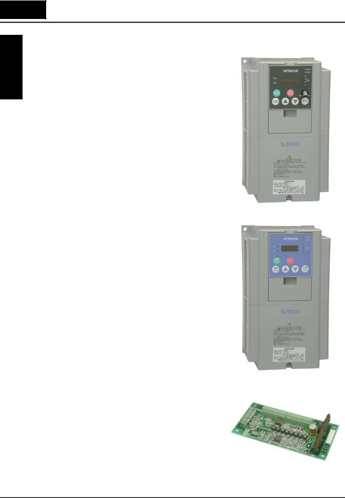
1–2
Introduction
Geting Started
Introduction
Main Features Congratulations on your purchase of an SJ300 Series Hitachi inverter! This inverter drive features state-of-the-art circuitry and components to provide high performance. The housing footprint is exceptionally small, given the size of the corresponding motor. The Hitachi SJ300 product line includes more than twenty inverter models to cover motor sizes from 1/2 horsepower to 200 horsepower, in either 230 VAC or 480 VAC power input versions. The main features are:
• 200V Class and 400V Class inverters
• U.S. or European version available
• Sensorless vector control
• Regenerative braking circuit
• Different operator keypads available for RUN/ STOP control and setting parameters
• Built-in RS-422 communications interface to allow configuration from a PC and for field bus
external modules
Model SJ300-037HFU (U.S. version)
•Sixteen programmable speed levels
•Motor constants are programmable, or may be set via auto-tuning
•PID control adjusts motor speed automatically to maintain a process variable value
The design of Hitachi inverters overcomes many of the traditional trade-offs between speed, torque and efficiency. The performance characteristics are:
•High starting torque of 150% rating or greater
•Continuous operation at 100% rated torque within a 1:10 speed range (6/60 Hz / 5/50 Hz) without motor derating
•Models from 0.4–11kW (1/2 to 15hp) have builtin dynamic braking units
•Cooling fan has ON/OFF selection to provide longer life
A full line of accessories from Hitachi is available to complete your motor control application. These include:
•Digital remote operator keypad
•Expansion card for sensor feedback
•Braking resistors
•Radio noise filters
•CE compliance filters
•Additional factory I/O network interface cards (to be announced)
Model SJ300-037HFE
(European version)
Expansion Card - Encoder Input
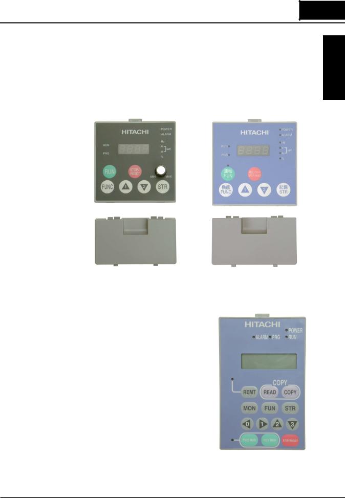
1–3
SJ300 Inverter
Digital Operator
Interface
Components
The SJ300 Series inverters have a detachable keypad (called a digital operator) on the front panel of the housing. The particular keypad that comes with the inverter depends on the country or continent corresponding to the particular model number. The standard digital operators occupy just part of the keypad recess in the panel. Therefore, the inverter comes with a snap-in panel filler plate that mounts below the keypad as shown.
These detachable keypads can be mounted in a NEMA cabinet panel door cut-out, for example. Threaded metal inserts on the rear of the keypads facilitate this external mounting configuration. A short cable then connects the keypad unit to the connector in the inverter keypad recess. See Chapter 3 for information on how to install and use these keypads and cables.
Started Getting
Digital Operator OPE-SRE |
Digital Operator OPE-S |
standard for -LFU and -HFU models |
standard for -HFE models |
The digital operator / copy unit is optional, and occupies the entire keypad recess when mounted. It has the additional capability of reading (uploading) the parameter settings in the inverter into its memory. Then you can install the copy unit on another inverter and write (download) the parameter settings into that inverter. OEMs will find this unit particularly useful, as one can use a single copy unit to transfer parameter settings from one inverter to many.
Other digital operator interfaces may be available from your Hitachi distributor for particular industries or international markets. Contact your Hitachi distributor for further details.
Optional Digital Operator / Copy Unit
SRW-0EX

1–4
Introduction
Geting Started
Removable
Components
The SJ300 Series inverters are designed for long life and ease of service. Several components are removable as shown below, aiding installation or parts replacement. Details on how and when to remove these parts are in the referenced chapters.
Fan Unit
(See Chapter 6 for servicing)
Digital Operator and Panel Filler Plate (See Chapter 3 for instructions)
Auxiliary fan (on some models)
Control Signal Terminal Block
(See Chapter 4 for wiring)
Capacitor Bank for DC Link |
Cable entry/exit plate |
(See Chapter 6 for servicing) |
(See Chapter 2 for instructions) |
|
|
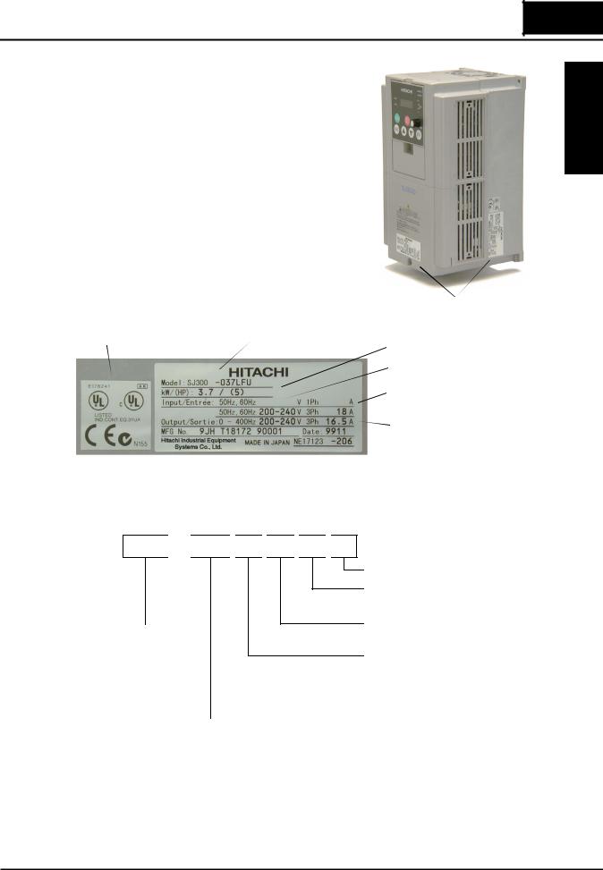
1–5
SJ300 Inverter
Specifications |
The Hitachi SJ300 inverters have product specifi- |
Label and Agency |
cations labels located on the front and the right |
Approvals |
side of the housing, as pictured to the right. Be |
|
sure to verify that the specifications on the labels |
|
match your power source, motor, and application |
|
safety requirements. |
|
|
Product Labels |
Regulatory agency approvals |
Specifications |
|
|
|
Inverter model number |
|
|
Motor capacity for this model |
|
|
Power Input Rating: |
|
|
frequency, voltage, phase, current |
|
|
Output Rating: |
|
|
frequency, voltage, current |
|
|
Manufacturing codes: |
|
|
lot number, date, etc. |
Model Number |
The model number for a specific inverter contains useful information about its operating |
|
Convention |
characteristics. Refer to the model number legend below: |
|
SJ300 

 004
004 
 H
H 
 F
F 
 U
U 
 2
2
Series
name
Version number (_, 2, 3, ...)
Restricted distribution: E=Europe, U=U.S., R=Japan
Configuration type
F = with digital operator (keypad)
Input voltage:
H = three-phase 400V class
L = three phase only, 200V class
|
|
Applicable motor capacity in kW |
|||
004 |
= 0.4 kW |
075 |
= 7.5 kW |
450 = 45 kW |
|
007 |
= 0.75 kW |
110 |
= 11 kW |
550 = 55 kW |
|
015 |
= 1.5 kW |
150 |
= 15 kW |
750 = 75 kW |
|
022 |
= 2.2 kW |
185 |
= 18.5 kW |
900 = 90 kW |
|
037 |
= 3.7 kW |
220 |
= 22 kW |
1100 = 110 kW |
|
040 |
= 4.0 kW |
300 |
= 30 kW |
1320 = 132 kW |
|
055 |
= 5.5 kW |
370 |
= 37 kW |
1500 = 150 kW |
|
Started Getting

1–6
SJ300 Inverter Specifications
Geting Started
SJ300 Inverter Specifications
Tables for 200V |
Note that “General Specifications” on page 1–9 covers all SJ300 inverters, followed by |
||||||||||||||||||||||||||
class inverters |
|
|
footnotes for all specifications tables. The 200V models in the upper table below (1/2 to 15 hp) |
||||||||||||||||||||||||
|
|
|
include internal dynamic braking units (see “Dynamic Braking” on page 5–6). |
|
|||||||||||||||||||||||
|
|
|
|
|
|
|
|
|
|
|
|
|
|
|
|
|
|
|
|
|
|||||||
Item |
|
|
|
|
|
|
|
200V Class Specifications |
|
|
|
|
|||||||||||||||
|
|
|
|
|
|
|
|
|
|
|
|
|
|
|
|
|
|
|
|
|
|
||||||
|
|
|
|
|
|
|
|
|
|
|
|
|
|
|
|
|
|
|
|
|
|
|
|
|
|
|
|
SJ300, 200V models, U.S. version |
|
004LFU |
|
007LFU |
015LFU |
|
022LFU |
037LFU |
|
055LFU |
|
075LFU |
110LFU |
||||||||||||||
|
|
|
|
|
|
|
|
|
|
|
|
|
|
|
|
|
|
|
|
|
|
|
|
|
|
||
Applicable motor size, 4-pole *2 |
|
HP |
1/2 |
|
1 |
|
2 |
|
3 |
|
|
5 |
|
|
|
7.5 |
|
|
10 |
|
15 |
||||||
|
|
|
|
|
|
|
|
|
|
|
|
|
|
|
|
|
|
|
|
|
|
|
|
|
|
|
|
|
|
|
|
|
kW |
0.4 |
|
0.75 |
|
1.5 |
|
2.2 |
|
3.7 |
|
|
|
5.5 |
|
|
7.5 |
|
11 |
||||
|
|
|
|
|
|
|
|
|
|
|
|
|
|
|
|
|
|
|
|
|
|
|
|||||
Rated capacity (200/240V) kVA |
|
1.0 / 1.2 |
|
1.7 / 2.0 |
2.5 / 3.1 |
|
3.6 / 4.3 |
|
5.7 / 6.8 |
|
8.3 / 9.9 |
|
11 / 13.3 |
|
15.9/ |
||||||||||||
|
|
|
|
|
|
|
|
|
|
|
|
|
|
|
|
|
|
|
|
|
|
|
|
|
|
|
19.1 |
|
|
|
|
|
|
|
|
|
|
|
|
|
|
|
|
|
|
|
|
|
|
||||||
Rated input voltage |
|
|
|
|
|
|
|
|
|
3-phase: 200 to 240V ±10%, 50/60 Hz ±5% |
|
|
|
|
|||||||||||||
|
|
|
|
|
|
|
|
|
|
|
|
|
|
|
|
|
|
|
|
|
|
|
|
|
|
|
|
Rated input current (A) |
|
|
|
3.8 |
|
5.5 |
|
8.3 |
|
12 |
|
|
18 |
|
|
|
26 |
|
|
35 |
|
51 |
|||||
|
|
|
|
|
|
|
|
|
|
|
|
|
|
|
|
|
|
|
|
||||||||
Rated output voltage |
*3 |
|
|
|
|
|
3-phase (3-wire) 200 to 240V (corresponding to input voltage) |
|
|||||||||||||||||||
|
|
|
|
|
|
|
|
|
|
|
|
|
|
|
|
|
|
|
|
|
|
|
|
|
|||
Rated output current (A) |
|
3.0 |
|
5.0 |
|
7.5 |
|
10.5 |
|
16.5 |
|
|
24 |
|
|
32 |
|
46 |
|||||||||
|
|
|
|
|
|
|
|
|
|
|
|
|
|
|
|
|
|
|
|
|
|
|
|
|
|||
Efficiency at 100% rated output, % |
|
85.1 |
|
89.5 |
|
92.3 |
|
93.2 |
|
94.0 |
|
|
94.4 |
|
|
94.6 |
|
94.8 |
|||||||||
|
|
|
|
|
|
|
|
|
|
|
|
|
|
|
|
|
|
|
|
|
|
|
|
|
|
|
|
Watt loss, |
|
|
at 70% output |
|
64 |
|
76 |
|
102 |
|
127 |
|
179 |
|
|
|
242 |
|
|
312 |
|
435 |
|||||
approximate (W) |
|
|
|
|
|
|
|
|
|
|
|
|
|
|
|
|
|
|
|
|
|
|
|
|
|
|
|
|
|
at 100% output |
70 |
|
88 |
|
125 |
|
160 |
|
235 |
|
|
|
325 |
|
|
425 |
|
600 |
|||||||
|
|
|
|
|
|
|
|
|
|
|
|
|
|||||||||||||||
|
|
|
|
|
|
|
|
|
|
|
|
|
|
|
|
|
|
|
|
|
|||||||
Starting torque *6 |
|
|
|
|
|
|
|
200% at 0.5 Hz (SLV), 150% at around 0 Hz (SLV, 0 Hz domain, |
|
||||||||||||||||||
|
|
|
|
|
|
with motor one frame size down), 100% at 0 Hz (with feedback board) |
|||||||||||||||||||||
|
|
|
|
|
|
|
|
|
|
|
|
|
|
|
|
|
|
|
|
|
|
|
|
|
|
||
Dynamic braking |
|
|
internal res. only |
|
|
50% |
|
|
|
|
|
|
|
|
|
|
20% |
|
|
|
|
10% |
|||||
approx. % torque, |
|
|
|
|
|
|
|
|
|
|
|
|
|
|
|
|
|
|
|
|
|
|
|
|
|
|
|
|
|
with external res. |
|
|
200% |
|
|
|
|
160% |
|
100% |
|
|
80% |
|
70% |
||||||||||
short time stop *7 |
|
|
|
|
|
|
|
|
|
|
|
|
|||||||||||||||
|
|
|
|
|
|
|
|
|
|
|
|
|
|
|
|
|
|
|
|
|
|
|
|
|
|
|
|
|
|
|
|
|
|
|
|
|
|
|
|
|
|
|
|
|
|
|
|
|
|||||||
DC braking |
|
|
|
|
|
|
|
|
Variable operating frequency, time, and braking force |
|
|||||||||||||||||
|
|
|
|
|
|
|
|
|
|
|
|
|
|
|
|
|
|
|
|
|
|
|
|
|
|||
Weight |
|
|
kg / lb |
|
3.5 / 7.7 |
|
3.5 / 7.7 |
3.5 / 7.7 |
|
3.5 / 7.7 |
|
3.5 / 7.7 |
|
3.5 / 7.7 |
|
5 / 11 |
|
5 / 11 |
|||||||||
|
|
|
|
|
|
|
|
|
|
|
|
|
|
|
|
|
|
|
|
||||||||
|
|
|
|
|
|
|
|
|
|
|
|
|
|
|
|
|
|
|
|
|
|
|
|
|
|
|
|
Item |
|
|
|
|
|
200V Class Specifications, continued |
|
|
|
|
|||||||||||||||||
|
|
|
|
|
|
|
|
|
|
|
|
|
|
|
|
|
|
|
|
|
|
|
|||||
|
|
|
|
|
|
|
|
|
|
|
|
|
|
|
|
|
|
|
|
|
|
|
|
|
|
|
|
SJ300, 200V models, U.S. version |
|
150LFU |
|
185LFU |
|
220LFU |
|
300LFU |
|
370LFU |
|
450LFU |
|
550LFU |
|||||||||||||
|
|
|
|
|
|
|
|
|
|
|
|
|
|
|
|
|
|
|
|
|
|
||||||
Applicable motor size |
*2 |
|
HP |
20 |
|
|
25 |
|
|
30 |
|
|
|
40 |
|
|
50 |
|
60 |
|
75 |
||||||
|
|
|
|
|
|
|
|
|
|
|
|
|
|
|
|
|
|
|
|
|
|
|
|
||||
|
|
|
|
|
kW |
15 |
|
|
18.5 |
|
|
22 |
|
|
|
30 |
|
|
37 |
|
45 |
|
55 |
||||
|
|
|
|
|
|
|
|
|
|
|
|
|
|
|
|
||||||||||||
Rated capacity (200/240V) kVA |
|
22.1 / 26.6 |
|
26.3 / 31.5 |
|
32.9 / 39.4 |
|
41.9 / 50.2 |
|
50.2/60.2 |
|
63 / 75.6 |
|
76.2/91.4 |
|||||||||||||
|
|
|
|
|
|
|
|
|
|
|
|
|
|
|
|
|
|||||||||||
Rated input voltage |
|
|
|
|
|
|
|
|
|
3-phase: 200 to 240V ±10%, 50/60 Hz ±5% |
|
||||||||||||||||
|
|
|
|
|
|
|
|
|
|
|
|
|
|
|
|
|
|
|
|
|
|||||||
Rated input current (A) |
|
|
|
70 |
|
|
84 |
|
|
105 |
|
|
|
133 |
|
|
160 |
|
200 |
|
242 |
||||||
|
|
|
|
|
|
|
|
|
|
|
|
|
|
||||||||||||||
Rated output voltage |
*3 |
|
|
|
|
|
3-phase (3-wire) 200 to 240V (corresponding to input voltage) |
|
|||||||||||||||||||
|
|
|
|
|
|
|
|
|
|
|
|
|
|
|
|
|
|
|
|||||||||
Rated output current (A) |
|
64 |
|
|
76 |
|
|
95 |
|
|
|
121 |
|
|
145 |
|
182 |
|
220 |
||||||||
|
|
|
|
|
|
|
|
|
|
|
|
|
|
|
|
|
|
|
|
||||||||
Efficiency at 100% rated output, % |
|
94.9 |
|
|
95.0 |
|
|
95.0 |
|
|
|
95.1 |
|
|
95.1 |
|
95.1 |
|
95.1 |
||||||||
|
|
|
|
|
|
|
|
|
|
|
|
|
|
|
|
|
|
|
|
|
|
|
|
||||
Watt loss, |
|
|
at 70% output |
|
575 |
|
|
698 |
|
|
820 |
|
|
|
1100 |
|
|
1345 |
|
1625 |
|
1975 |
|||||
approximate (W) |
|
|
|
|
|
|
|
|
|
|
|
|
|
|
|
|
|
|
|
|
|
|
|
|
|
|
|
|
|
at 100% output |
800 |
|
|
975 |
|
|
1150 |
|
|
1550 |
|
|
1900 |
|
2300 |
|
2800 |
||||||||
|
|
|
|
|
|
|
|
|
|
|
|
|
|||||||||||||||
|
|
|
|
|
|
|
|
|
|
|
|
|
|
|
|
||||||||||||
Starting torque *6 |
|
|
|
|
|
|
|
200% at 0.5 Hz (SLV), 150% at around 0 Hz (SLV, 0 Hz domain, |
|
||||||||||||||||||
|
|
|
|
|
|
with motor one frame size down), 100% at 0 Hz (with feedback board) |
|||||||||||||||||||||
|
|
|
|
|
|
|
|
|
|
|
|
|
|
|
|
|
|
|
|
|
|
|
|
|
|||
Dynamic braking |
|
|
w/o braking unit |
|
|
|
|
|
|
|
|
|
|
10% |
|
|
|
|
|
|
|
|
|
||||
approx. % torque, |
|
|
|
|
|
|
|
|
|
|
|
|
|
|
|
|
|
|
|
|
|
|
|
|
|
|
|
|
|
with braking unit |
30–200% |
|
25–170% |
|
25–150% |
|
55–110% |
|
45–90% |
|
35–75% |
|
30–60% |
||||||||||||
short time stop *7 |
|
|
|
|
|
|
|
|
|||||||||||||||||||
|
|
|
|
|
|
|
|
|
|
|
|
|
|
|
|
|
|
|
|
|
|
|
|
|
|
|
|
|
|
|
|
|
|
|
|
|
|
|
|
|
|
|
|
||||||||||||
DC braking |
|
|
|
|
|
|
|
|
Variable operating frequency, time, and braking force |
|
|||||||||||||||||
|
|
|
|
|
|
|
|
|
|
|
|
|
|
|
|
|
|
|
|
|
|||||||
Weight |
|
|
kg / lb |
|
12 / 26.4 |
|
|
12 / 26.4 |
|
12 / 26.4 |
|
20 / 44 |
|
|
30 / 66 |
|
30 / 66 |
|
50 / 110 |
||||||||
|
|
|
|
|
|
|
|
|
|
|
|
|
|
|
|
|
|
|
|
|
|
|
|
|
|
|
|

1–7
SJ300 Inverter
Tables for 400V |
Note that “General Specifications” on page 1–9 covers all SJ300 inverters, followed by |
||||||||||
class inverters |
footnotes for all specifications tables. The 400V models in the upper table below (1 to 15 hp) |
||||||||||
|
|
include internal dynamic braking units (see “Dynamic Braking” on page 5–6). |
|
||||||||
|
|
|
|
|
|
|
|
|
|
|
|
Item |
|
|
|
|
|
400V Class Specifications |
|
|
|||
|
|
|
|
|
|
|
|
|
|
|
|
|
|
|
|
|
|
|
|
|
|
|
|
SJ300 inverters, |
|
U.S. version |
|
007HFU |
015HFU |
022HFU |
040HFU |
055HFU |
075HFU |
110HFU |
|
400V models |
|
|
|
|
|
|
|
|
|
|
|
|
European ver. |
007HFE |
015HFE |
022HFE |
040HFE |
055HFE |
075HFE |
110HFE |
|||
|
|
||||||||||
|
|
|
|
|
|
|
|
|
|
|
|
Applicable motor size |
*2 |
|
HP |
1 |
2 |
3 |
5 |
7.5 |
10 |
15 |
|
|
|
|
|
|
|
|
|
|
|
|
|
|
|
|
|
kW |
0.75 |
1.5 |
2.2 |
4.0 |
5.5 |
7.5 |
11 |
|
|
|
|
|
|
|
|
|
|
||
Rated capacity (400 / 480V) kVA |
|
1.7 / 2.0 |
2.6 / 3.1 |
3.6 / 4.4 |
5.9 / 7.1 |
8.3 / 9.9 |
11 / 13.3 |
15.9/19.1 |
|||
|
|
|
|
|
|
|
|
|
|
|
|
Rated input voltage |
|
|
|
|
3-phase (3-wire) 380 to 480V ±10%, 50/60 Hz ±5% |
|
|||||
|
|
|
|
|
|
|
|
|
|||
Rated input current (A) |
|
2.8 |
4.2 |
5.8 |
9.5 |
13 |
18 |
25 |
|||
|
|
|
|
|
|
|
|
|
|||
Rated output voltage *3 |
|
|
3-phase (3-wire): 380 to 480V (corresponding to input voltage) |
|
|||||||
|
|
|
|
|
|
|
|
|
|||
Rated output current (A) |
|
2.5 |
3.8 |
5.3 |
8.6 |
12 |
16 |
23 |
|||
|
|
|
|
|
|
|
|
|
|||
Efficiency at 100% rated output, % |
|
89.5 |
92.3 |
93.2 |
94.0 |
94.4 |
94.6 |
94.8 |
|||
|
|
|
|
|
|
|
|
|
|
||
Watt loss, |
|
at 70% output |
76 |
102 |
127 |
179 |
242 |
312 |
435 |
||
approximate (W) |
|
|
|
|
|
|
|
|
|
|
|
|
at 100% output |
88 |
125 |
160 |
235 |
325 |
425 |
600 |
|||
|
|
||||||||||
|
|
|
|
|
|
|
|
|
|
|
|
Starting torque *6 |
|
|
|
|
200% at 0.5 Hz (SLV), 150% at around 0 Hz (SLV, 0 Hz domain, |
|
|||||
|
|
|
|
|
with motor one frame size down), 100% at 0 Hz (with feedback board) |
||||||
|
|
|
|
|
|
|
|
|
|
||
Dynamic braking |
|
internal res. only |
50% |
|
20% |
|
10% |
||||
approx. % torque, |
|
|
|
|
|
|
|
|
|
|
|
|
with external res. |
|
200% |
|
140% |
100% |
70% |
||||
short time stop *7 |
|
|
|
||||||||
|
|
|
|
|
|
|
|
|
|
|
|
|
|
|
|
|
|
|
|
|
|
|
|
DC braking |
|
|
|
|
Variable operating frequency, time, and braking force |
|
|||||
|
|
|
|
|
|
|
|
|
|
|
|
Weight |
|
kg / lb |
|
3.5 / 7.7 |
3.5 / 7.7 |
3.5 / 7.7 |
3.5 / 7.7 |
3.5 / 7.7 |
5 / 11 |
5 / 11 |
|
|
|
|
|
|
|
|
|
|
|
|
|
|
|
|
|
|
|
|
|
|
|
|
|
Item |
|
|
|
|
|
400V Class Specifications |
|
|
|||
|
|
|
|
|
|
|
|
|
|
|
|
|
|
|
|
|
|
|
|
|
|
|
|
SJ300 inverters, |
|
U.S. version |
|
150HFU |
185HFU |
220HFU |
300HFU |
370HFU |
450HFU |
550HFU |
|
400V models |
|
|
|
|
|
|
|
|
|
|
|
|
European ver. |
150HFE |
185HFE |
220HFE |
300HFE |
370HFE |
450HFE |
550HFE |
|||
|
|
||||||||||
|
|
|
|
|
|
|
|
|
|
|
|
Applicable motor size |
*2 |
|
HP |
20 |
25 |
30 |
40 |
50 |
60 |
75 |
|
|
|
|
|
|
|
|
|
|
|
|
|
|
|
|
|
kW |
15 |
18.5 |
22 |
30 |
37 |
45 |
55 |
|
|
|
|
|
|
|
|
|
|
||
Rated capacity (400 / 480V) kVA |
|
22.1 / 26.6 |
26.3 / 31.5 |
33.2 / 39.9 |
40.1 / 48.2 |
51.9 / 62.3 |
62.3 / 74.8 |
76.2/91.4 |
|||
|
|
|
|
|
|
|
|
|
|
|
|
Rated input voltage |
|
|
|
|
3-phase (3-wire) 380 to 480V ±10%, 50/60 Hz ±5% |
|
|||||
|
|
|
|
|
|
|
|
|
|||
Rated input current (A) |
|
35 |
42 |
53 |
64 |
83 |
99 |
121 |
|||
|
|
|
|
|
|
|
|
|
|||
Rated output voltage *3 |
|
|
3-phase (3-wire): 380 to 480V (corresponding to input voltage) |
|
|||||||
|
|
|
|
|
|
|
|
|
|||
Rated output current (A) |
|
32 |
38 |
48 |
58 |
75 |
90 |
110 |
|||
|
|
|
|
|
|
|
|
|
|||
Efficiency at 100% rated output, % |
|
94.9 |
95.0 |
95.0 |
95.1 |
95.1 |
95.1 |
95.1 |
|||
|
|
|
|
|
|
|
|
|
|||
Watt loss, |
|
at 70% output |
575 |
698 |
820 |
1100 |
1345 |
1625 |
1975 |
||
approximate (W) |
|
|
|
|
|
|
|
|
|
|
|
|
at 100% output |
800 |
975 |
1150 |
1550 |
1900 |
2300 |
2800 |
|||
|
|
||||||||||
|
|
|
|
|
|
|
|
|
|
|
|
Starting torque *6 |
|
|
|
|
200% at 0.5 Hz (SLV), 150% at around 0 Hz (SLV, 0 Hz domain, |
|
|||||
|
|
|
|
|
with motor one frame size down), 100% at 0 Hz (with feedback board) |
||||||
|
|
|
|
|
|
|
|
|
|||
Dynamic braking |
|
w/o braking unit |
|
|
|
10% |
|
|
|
||
approx. % torque, |
|
|
|
|
|
|
|
|
|
|
|
|
with braking unit |
40–200% |
40–200% |
35–200% |
110–170% |
90–150% |
70–120% |
60–100% |
|||
short time stop *7 |
|
||||||||||
|
|
|
|
|
|
|
|
|
|
|
|
|
|
|
|
|
|
|
|
|
|
|
|
DC braking |
|
|
|
|
Variable operating frequency, time, and braking force |
|
|||||
|
|
|
|
|
|
|
|
|
|
||
Weight |
|
kg / lb |
|
12 / 26.4 |
12 / 26.4 |
12 / 26.4 |
20 / 44 |
30 / 66 |
30 / 66 |
50 / 110 |
|
|
|
|
|
|
|
|
|
|
|
|
|
Started Getting

1–8
SJ300 Inverter Specifications
Tables for 400V class inverters, continued...
Started |
|
|
|
|
|
|
|
|
|
|
|
|
Item |
|
|
400V Class Specifications |
|
||||||
|
|
|
|
|
|||||||
|
|
|
|
|
|
|
|
|
|
|
|
|
|
|
|
|
|
|
|
|
|
|
|
Geting |
|
SJ300 inverters, |
|
U.S. version |
|
750HFU |
900HFU |
1100HFU |
— |
1500HFU |
|
|
400V models |
|
|
|
|
|
|
|
|
|
|
|
|
|
European ver. |
750HFE |
900HFE |
1100HFE |
1320HFE |
— |
|||
|
|
|
|
||||||||
|
|
|
|
|
|
|
|
|
|
|
|
|
|
Applicable motor size |
*2 |
|
HP |
100 |
125 |
150 |
175 |
200 |
|
|
|
|
|
|
|
|
|
|
|
|
|
|
|
|
|
|
|
kW |
75 |
90 |
110 |
132 |
150 |
|
|
|
|
|
|
||||||
|
|
|
|
|
|
|
|
|
|
||
|
|
Rated capacity (400 / 480V) kVA |
|
103.2 / 123.8 |
121.9 / 146.3 |
150.3 / 180.4 |
180.1 / 216.1 |
180.1 / 216.1 |
|||
|
|
|
|
|
|
|
|
|
|
|
|
|
|
Rated input voltage |
|
|
|
|
|
3-phase (3-wire) 380 to 480V ±10%, 50/60 Hz ±5% |
|
||
|
|
|
|
|
|
|
|
|
|||
|
|
Rated input current (A) |
|
164 |
194 |
239 |
286 |
286 |
|||
|
|
|
|
|
|
|
|
|
|
|
|
|
|
Rated output voltage |
*3 |
|
|
3-phase (3-wire): 380 to 480V (corresponding to input voltage) |
|||||
|
|
|
|
|
|
|
|
|
|||
|
|
Rated output current (A) |
|
149 |
176 |
217 |
260 |
260 |
|||
|
|
|
|
|
|
|
|
|
|||
|
|
Efficiency at 100% rated output, % |
|
95.2 |
95.2 |
95.2 |
95.2 |
95.2 |
|||
|
|
|
|
|
|
|
|
|
|
|
|
|
|
Watt loss, |
|
at 70% output |
2675 |
3375 |
3900 |
4670 |
4670 |
||
|
|
approximate (W) |
|
|
|
|
|
|
|
|
|
|
|
|
at 100% output |
3800 |
4800 |
5550 |
6650 |
6650 |
|||
|
|
|
|
||||||||
|
|
|
|
|
|
|
|
|
|
|
|
|
|
Starting torque *6 |
|
|
|
|
180% at 0.5 Hz (SLV), 130% at around 0 Hz (SLV, 0 Hz domain, |
||||
|
|
|
|
|
|
|
with motor one frame size down), 100% at 0 Hz (with feedback board) |
||||
|
|
|
|
|
|
|
|
|
|
|
|
|
|
Dynamic braking |
|
w/o braking unit |
|
|
10% |
|
|
||
|
|
approx. % torque, |
|
|
|
|
|
|
|
|
|
|
|
|
with braking unit |
45–70% |
40–60% |
30–50% |
25–40% |
20–35% |
|||
|
|
short time stop *7 |
|
||||||||
|
|
|
|
|
|
|
|
|
|
|
|
|
|
|
|
|
|
|
|
|
|
|
|
|
|
DC braking |
|
|
|
|
|
Variable operating frequency, time, and braking force |
|
||
|
|
|
|
|
|
|
|
|
|
|
|
|
|
Weight |
|
kg / lb |
|
60 / 132 |
60 / 132 |
80 / 176 |
80 / 176 |
80 / 176 |
|
|
|
|
|
|
|
|
|
|
|
|
|
Footnotes for the preceding tables and the table that follows:
Note 1: The protection method conforms to JEM 1030.
Note 2: The applicable motor refers to Hitachi standard 3-phase motor (4-pole). When using other motors, care must be taken to prevent the rated motor current (50/60 Hz) from exceeding the rated output current of the inverter.
Note 3: The output voltage decreases as the main supply voltage decreases (except when using the AVR function). In any case, the output voltage cannot exceed the input power supply voltage.
Note 4: To operate the motor beyond 50/60 Hz, consult the motor manufacturer for the maximum allowable rotation speed.
Note 5: When SLV is selected, please set the carrier frequency higher than 2.1 kHz. Note 6: At the rated voltage when using a Hitachi standard 3-phase, 4-pole motor (when
selecting sensorless vector control—SLV).
Note 7: The braking torque via capacitive feedback is the average deceleration torque at the shortest deceleration (stopping from 50/60 Hz as indicated). It is not continuous regenerative braking torque. The average decel torque varies with motor loss. This value decreases when operating beyond 50 Hz. If a large regenerative torque is required, the optional regenerative braking resistor should be used.
Note 8: The frequency command will equal the maximum frequency at 9.8V for input voltage 0 to 10 VDC, or at 19.6 mA for input current 4 to 20 mA. If this characteristic is not satisfactory for your application, contact your Hitachi sales representative.
Note 9: The storage temperature refers to the short-term temperature during transport. Note 10: Conforms to the test method specified in JIS C0911 (1984). For the model types
excluded in the standard specifications, contact your Hitachi sales representative. Note 11: NEMA 1 applies up to 22kW. An optional wire-entry conduit box is required for
30kW to 55kW models to meet NEMA 1 rating.

1–9
SJ300 Inverter
General |
|
|
The following table (continued on next page) applies to all SJ300 inverter models. |
|
Specifications |
|
|
||
|
|
|
|
|
|
Item |
General Specifications |
||
|
|
|
|
|
|
|
|||
Protective enclosure *1, *11 |
IP20 (NEMA 1) |
|||
|
|
|
||
Control method |
|
Line-to-line sine wave pulse-width modulation (PWM) control |
||
|
|
|||
Output frequency range *4 |
0.1 to 400 Hz |
|||
|
|
|
||
Frequency accuracy |
|
Digital command: ± 0.01% of the maximum frequency |
||
|
|
|
|
Analog command: ± 0.2% (25°C ± 10°C) |
|
|
|||
Frequency setting resolution |
Digital: ± 0.01 Hz; Analog: (max. frequency)/4000, [O] terminal: 12-bit 0 to 10V; |
|||
|
|
|
|
[OI] terminal: 12-bit, 4-20mA; [O2] terminal: 12-bit -10 to +10V |
|
|
|||
Volt./Freq. characteristic *5 |
V/F optionally variable (30 to 400Hz base frequency), V/F control (constant torque, |
|||
|
|
|
|
reduced torque), sensorless vector control |
|
|
|
||
Speed fluctuation |
|
± 0.5% (sensorless vector control) |
||
|
|
|||
Overload capacity (output current) |
150% for 60 seconds, 200% (180% for 75kW / 100HP and larger) for 0.5 seconds |
|||
|
|
|||
Acceleration/deceleration time |
0.01 to 3600 sec., (linear curve profiles, accel./decel. selection), two-stage accel./decel. |
|||
|
|
|
|
|
Input |
Freq. |
|
Operator keypad |
Up and Down keys / Value settings |
signal |
setting |
|
|
|
|
Potentiometer |
Analog setting via potentiometer on operator keypad |
||
|
|
|
||
|
|
|
|
|
|
|
|
External signal *8 |
0 to 10 VDC (input impedance 10k Ohms), 4 to 20 mA (input impedance 250 Ohms), |
|
|
|
|
Potentiometer (1k to 2k Ohms, 2W) |
|
|
|
|
|
|
|
|
Serial port |
RS485 interface |
|
|
|
|
|
|
FW/RV |
|
Operator panel |
Run key / Stop key (change FW/RV by function command) |
|
Run |
|
|
|
|
|
External signal |
FW Run/Stop (NO contact), RV set by terminal assignment (NC/NO), |
|
|
|
|
||
|
|
|
|
3-wire input available |
|
|
|
|
|
|
Intelligent Input |
RV (reverse run/stop), CF1~CF4 (multi-speed select), JG (jogging), DB (external DC |
||
|
terminals (assign eight |
braking), SET (set 2nd motor data), 2CH (2-stage accel./decel.), FRS (free-run stop), |
||
|
functions to terminals) |
EXT (external trip), USP (unattended start protection), CS (commercial power source), |
||
|
|
|
|
SFT (software lock), AT (analog input voltage/current select), SET3 (set 3rd motor |
|
|
|
|
data), RS (reset inverter), STA (start, 3-wire interface), STP (stop, 3-wire interface), |
|
|
|
|
F/R (FW/RV 3-wire interface), PID (PID ON/OFF), PIDC (PID reset), CAS (control |
|
|
|
|
gain setting), UP (remote control Up function, motorized speed pot.), DWN (remote |
|
|
|
|
control Down function, motorized speed pot.), UDC (remote control data clearing), |
|
|
|
|
OPE (Operator control), SF1-SF7 (Multispeed bits 0-7), OLR (Overload limit change), |
|
|
|
|
TL (torque limit enable), TRQ1 (torque limit selection bit 1, LSB), TRQ2 (torque limit |
|
|
|
|
selection bit 2, MSB), PPI (Proportional / Proportional/Integral mode selection), BOK |
|
|
|
|
(Brake confirmation signal), ORT (Orientation – home search), LAC (LAC: LAD |
|
|
|
|
cancel), PCLR (Position deviation reset), STAT (pulse train position command input |
|
|
|
|
enable), NO (not selected) |
|
|
|
||
|
Thermistor input |
One terminal (PTC characteristics) |
||
|
|
|
||
Output |
Intelligent Output terminals |
RUN (run signal), FA1 (Frequency arrival type 1 – constant speed), FA2 (Frequency |
||
signal |
(assign six functions to five |
arrival type 2 – over-frequency), OL (overload advance notice signal 1), OD (Output |
||
|
open collector outputs and |
deviation for PID control), AL (alarm signal), FA3 (Frequency arrival type 3 – at- |
||
|
one relay NO-NC contact) |
frequency), OTQ (over-torque signal), IP (Instantaneous power failure signal), UV |
||
|
|
|
|
(Under-voltage signal), TRQ (In torque limit), RNT (Run time over), ONT (Power-ON |
|
|
|
|
time over), THM (thermal alarm), BRK (Brake release signal), BER (Brake error |
|
|
|
|
signal), ZS (Zero speed detect), DSE (speed deviation maximum), POK (Positioning |
|
|
|
|
completion), FA4 (Frequency arrival type 4 – over-frequency 2), FA5 (Frequency arrival |
|
|
|
|
type 5 – at-frequency 2), OL2 (Overload notice advance signal 2), Terminals 11-13 or |
|
|
|
|
11-14 automatically configured as AC0-AC2 or AC0-AC3 per alarm code output selec- |
|
|
|
|
tion) |
|
|
|
||
|
Intelligent monitor output |
Analog voltage monitor, analog current monitor (8-bit resolution), and PWM output, on |
||
|
terminals |
|
terminals [AM], [AMI], [FM] |
|
|
|
|
|
|
Display monitor |
|
Output frequency, output current, motor torque, scaled value of output frequency, trip |
||
|
|
|
|
history, I/O terminal condition, input power, output voltage |
|
|
|
|
|
Started Getting

1–10
SJ300 Inverter Specifications
Started |
|
|
|
Item |
General Specifications |
|
|
|
|
|
|
|
|
|
|
|
|
|
Other user-settable parameters |
V/F free-setting (up to 7 points), freq. upper/lower limit, freq. jump, accel/decel curve |
|||
|
|
||||
|
|
|
|
|
selection, manual torque boost value and freq. adjustment, analog meter tuning, start |
Geting |
|
|
|
|
frequency, carrier frequency, electronic thermal protection level, external frequency |
|
|
|
|
output zero/span reference, external frequency input bias start/end, analog input selec- |
|
|
|
|
|
|
|
|
|
|
|
|
tion, retry after trip, restart after instantaneous power failure, various signal outputs, |
|
|
|
|
|
reduced voltage start, overload restriction, default value setting (US, Europe, Japan), |
|
|
|
|
|
deceleration and stop after power failure, AVR function, fuzzy accel/decel, auto-tuning |
|
|
|
|
|
(on-line/off-line), high-torque multi-operation, automatic energy-saving operation |
|
|
|
|
|
|
|
|
|
|
||
|
|
Carrier frequency range |
Models SJ300–015xxx to 750xxx: 0.5 to 12 kHz |
||
|
|
|
|
|
Models SJ300–900Hxx to 1320Hxx: 0.5 to 8 kHz |
|
|
|
|
||
|
|
Protective functions |
Over-current, overload, braking resistor overload, over voltage, EEPROM error, under- |
||
|
|
|
|
|
voltage error, CT (current transformer) error, CPU error, external trip, USP error, |
|
|
|
|
|
ground fault, input over voltage, instantaneous power failure, expansion card 1 error, |
|
|
|
|
|
expansion card 2 error, inverter thermal trip, phase failure detection, IGBT error, |
|
|
|
|
|
thermistor error |
|
|
|
|
|
|
|
|
Environ- |
|
Temperature (*9) |
Operating (ambient): -10 to 50°C / Storage: -20 to 65°C |
|
|
ment |
|
|
|
|
|
|
Humidity |
20 to 90% humidity (non-condensing) |
|
|
|
|
|
||
|
|
|
|
|
|
|
|
|
|
Vibration *10 |
Models SJ300–004xxx to 220xxx: 5.9 m/s2 (0.6G), 10 to 55 Hz |
|
|
|
|
|
Models SJ00–300xx to 1500xxx: 2.94 m/s2 (0.3G), 10 to 55 Hz |
|
|
|
|
Location |
Altitude 1,000 m or less, indoors (no corrosive gasses or dust) |
|
|
|
|
|
|
|
|
Coating color |
|
Gray |
|
|
|
|
|
|
|
|
|
Accessories |
|
Feedback PCB |
SJ-FB (vector control loop speed sensor) |
|
|
|
|
|
|
|
|
|
|
Digital input PCB |
SJ-DG (4-digit BCD / 16-bit binary) |
|
|
|
|
|
|
|
|
|
|
Others |
EMI filters, input/output reactors, DC reactors, radio noise filters, braking resistors, |
|
|
|
|
|
braking units, LCR filter, communication cables, factory I/O network interface cards |
|
|
|
|
|
|
|
|
Operator input devices |
OPE–SRE (4-digit LED with potentiometer) / OPE–S (4-digit LED w/o potentiometer), |
||
|
|
|
|
|
Optional: OPE-SR (4-digit LED with potentiometer, Japanese/English overlay), |
|
|
|
|
|
SRW–0EX Multilingual operator with copy function (English, French, German, Italian, |
|
|
|
|
|
Spanish, and Portuguese) |
|
|
|
|
|
|
Signal Ratings Detailed ratings are in “Specifications of Control and Logic Connections” on page 4–9.
|
Signal / Contact |
Ratings |
|
|
|
|
|
|
|
|
|
|
Built-in power for inputs |
24VDC supply, 100 mA maximum |
|
|
|
|
|
|
Intelligent (programmable) logic inputs |
27VDC maximum, 4.7kΩ input impedance |
|
|
|
|
|
|
Intelligent (programmable) logic outputs |
Open collector type, 50mA max. ON state current, 27 VDC maximum OFF state voltage |
|
|
|
|
|
|
Thermistor input |
Minimum thermistor power 100mW |
|
|
|
|
|
|
PWM output |
0 to 10VDC, 1.2 mA max., 50% duty cycle |
|
|
|
|
|
|
Voltage analog output |
0 to 10VDC, 2 mA max. |
|
|
|
|
|
|
Current analog output |
4-20 mA, nominal load impedance 250Ω |
|
|
|
|
|
|
Analog input, current |
4 to 19.6 mA range, 20 mA nominal |
|
|
|
|
|
|
Analog input, voltage |
0 to 9.6 VDC range, 10VDC nominal, 12VDC max., input impedance 10 kΩ |
|
|
|
|
|
|
+10V analog reference |
10VDC nominal, 10 mA maximum |
|
|
|
|
|
|
Alarm relay, normally closed contacts |
Maximum loads: 250VAC, 2A; 30VDC, 8A resistive load |
|
|
|
250VAC, 0.2A; 30VDC, 0.6A inductive load |
|
|
|
Minimum loads: 100 VAC, 10mA; 5VDC, 100mA |
|
|
|
|
|
|
Alarm relay, normally open contacts |
250VAC, 1A; 30VDC 1A max. resistive load / |
|
|
|
250VAC, 0.2A; 30VDC, 0.2A max. inductive load |
|
|
|
Min. loads: 100 VAC, 10mA; 5VDC, 100mA |
|
|
|
|
|
|
|
|
|
 Loading...