


L100
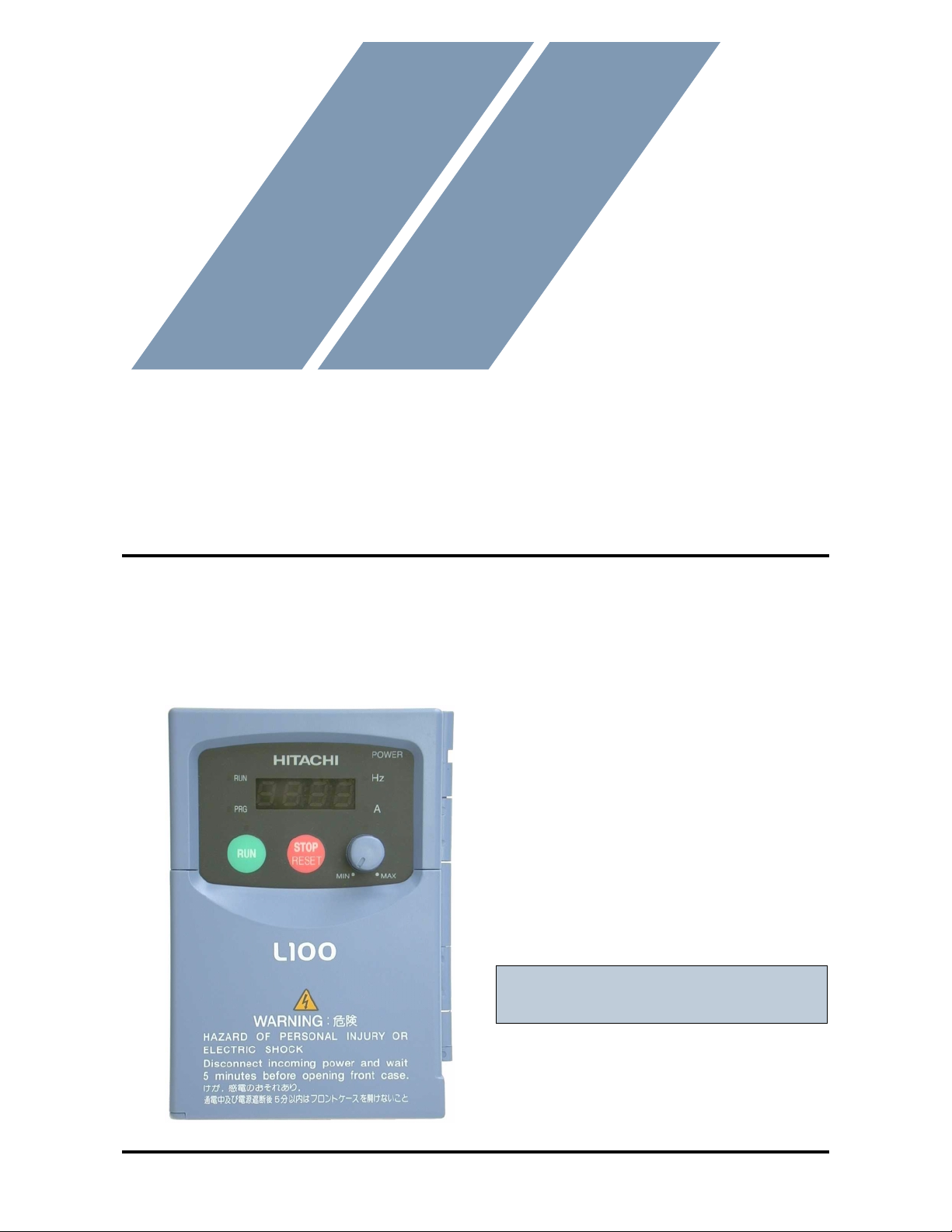
HITACHI
L100 Series Inverter
Instruction Manual
• Single-phase Input 200V Class
• Three-phase Input 200V Class
• Three-phase Input 400V Class
After reading this manual,
keep it handy for future reference.
Hitachi, Ltd.
Tokyo Japan
Manual Number: NB576XA
Technologies Inc.
Toll Free: voice: 1-877-539-2542 fax: 1-800-539-2542 www.mgitech.com

L100 Inverter
xv
Safety Messages .................................................................................................................. iii
Hazardous High Voltage ....................................................... ........ ........ ........ . ...... ........ .......iii
General Precauti o n s - Read Th ese First! ...................... .............. ........................... .............. .iv
Precautions for EMC (Electromagnetic Compatibility) .......................................................vi
Index to Warnings and Cautions in This Manual ....................... .............. ............... ........... v ii
General Warnings an d Ca u tio n s .................. ............... .......................... ............... ............... xii
Revisions .......................................................................................................................... xvii
Chapter 1: Getting Started
Introduction .......................................................................................................................1–2
L100 Inverter Specifications .............................................................................................1–4
Introduction to Variable-Frequency Drives ......................................................................1–7
Frequently Asked Questions ...........................................................................................1–12
Chapter 2: Inverter Mounting and Installation
Orientation to Inverte r Features ............ .............. ............... .............. ........................... ......2– 2
Basic System Description ..................................................................................................2–5
Step-by-Step Basic Installation .........................................................................................2–6
Powerup Test ...................................................................................................................2–17
Using the Front Panel Keypad ........................................................................................2–19
Chapter 3: Configuring Drive Parameters
Choosing a Progr amming Device ................................ .......................... ...........................3–2
Using Keypad Devi ces .......................... ....................................... .....................................3–3
Using the PC Software — DOP Plus .......... ............... .............. .............. ...........................3–6
“D” Group: Monitoring Functions ....................................................................................3–8
“F” Group: Main Profile Parameters .................................................................................3–9
“A” Group: Standard Functions ......................................................................................3–10
“B” Group: Fine Tuning Functions .................................................................................3–21
“C” Group: Intelligent Terminal Functions ....................................................................3–27
Chapter 4: Operations and Monitoring
Introduction .......................................................................................................................4–2
Connecting to PLCs an d Other Devices .......... ............... ....................................... ............4–4
Using Intelligent Input Terminals ........... ................... ................ ............................... ........ 4–6
Using Intelligent Output Terminals ........... .. ................................. ................ ................. ..4–18
Analog Input Operation ...................................................................................................4–24
Analog and Digital Monitor Output ................................................................................4–25
PID Loop Operation .......................................... ......................... .............. .......................4–27
Configuring the Inverter for Multiple Motors .................................... .......... ...................4–28
Table of Contents
Technologies Inc.
Toll Free: voice: 1-877-539-2542 fax: 1-800-539-2542 www.mgitech.com

Table of Contents
xvi
Chapter 5: Motor Control Accessories
Introduction ... ................ ................. ................ ............... ................ ................ ............... .....5–2
Component Descriptions ...................................................................................................5–3
Chapter 6: Troubleshooting and Maintenance
Troubleshooting ................................................................................................................6–2
Monitoring Trip Events, History, & Conditions ...............................................................6–5
Restoring Factory Default Settings ...................................................................................6–8
Maintenance and In s p ection .................... .............. ........................... .............. ..................6–9
Warranty .........................................................................................................................6–14
Appendix A: Glossary and Bibliography
Glossary ...........................................................................................................................A–2
Bibliography ....................................................................................................................A–8
Appendix B: Drive Parameter Settings Tables
Introduction ... ................ ................. ................ ............... ................ ................ ............... .... B–2
Parameter Settings fo r Ke y p a d En try ............ ............... .............. .............. ............... ........ B–2
Parameter Settings fo r DO P/DRW/DOP Plus .................... .............. .............. ................. B–7
Index
Technologies Inc.
Toll Free: voice: 1-877-539-2542 fax: 1-800-539-2542 www.mgitech.com
L100 Inverter
i
Safety Messages
For the best results with the L100 Series inverter, carefully read this manual and all of
the warning labels attached to the inverter before installing and operating it, and follow
the instructions exactly. Keep this manual handy for quick reference.
Definitions and Symbols
A safety instruction (message) includes a hazard alert symbol and a signal word,
WARNING or CAUTION. Each signal word has the following meaning:
HIGH VOLTAGE: This symbol indicates high voltage. It calls your attention to items
or operations that could be dangerous to you and other persons operation this equipment.
Read the message and follow the ins tructions carefully.
This symbol is the “Safety Alert Symbol.” It occurs with either of two signal words:
CAUTION or WARNING, as described below.
WARNING: Indicates a potentially haza rdous situation which, if not a voided, can result
in serious injury or death.
CAUTION: Indicates a potentially hazardous situation which, if not avoided, can result
in minor to moderate injury, or serious damage to the product. The situation described in
the CAUTION may, if not avoided, lead to serious results. Important sa fety measures
are described in CAUTION (as well as WARNING), so be sure to observe them.
1 Step 1: Indicates a step in a series of action steps to accomplish a goal.
NOTE: Notes indicate an area or subject of special merit, emphasizing either the
product’s capabilities or common errors in operation or maintenance.
TIP: Tips give a special instruction that can save time or provide other benef its while
installing or using the product. The tip calls attention to an idea that may not be obvious
to first-time users of the product.
Hazardous High Voltage
HIGH VOLT A GE: Motor control equipment and electronic c ontrollers are connected to
hazardous line voltages. When servicing drives and electronic controllers, there may be
exposed components with housings or protrusions at or above line potential. Extreme
care should be taken to protect against shock.
Stand on an insulating pad and make it a habit to use only one hand when checking com-
ponents. Always work with another person in case an emergenc y occurs. Disconnect
power before checking controllers or performing maintenance. Be sure equipment is
properly grounded. Wear safety glasses whenever wor king on electronic controllers or
rotating machinery.
Technologies Inc.
Toll Free: voice: 1-877-539-2542 fax: 1-800-539-2542 www.mgitech.com
ii
General Precautions - Read These First!
General Precautions - Read These First!
WARNING: This equipment should be installed, adjusted, and serviced by qualified
electrical maintenance personnel familiar with the construction and operation of the
equipment and the hazards inv olved. Failure to observe this precaution could result in
bodily injury.
WARNING: The user is responsible for ensuring that all driven machinery, drive train
mechanism not supplied by Hitachi, Ltd., and process line material are capable of safe
operation at an applied frequency of 150% of the maximum selected frequency range to
the AC motor. Failure to do so can result in destruction of equipment and injury to
personnel should a single-point failure occur .
WARNING: For equipment protection, install a ground leak age type break er with a f ast
response circuit capable of handling large currents. The ground f ault protection circuit is
not designed to protect against personal injury.
HIGH VOLTAGE: HAZARD OF ELECTRICAL SHOCK. DISCONNECT I NCOM-
ING POWER BEFORE WORKING ON THIS CONTROL .
WARNING: Wait at least five (5) minutes after turning off the input power supply
before performing maintenance or an inspection. Otherwise, there is the danger of
electric shock.
CAUTION: These instructions should be read and clearly understood before working
on L100 series equipment.
CAUTION: Proper grounds, disconnecting devices and other safety devices and their
location are the responsibility of the user and are not provided by Hitachi, Ltd.
CAUTION: Be sure to connect a motor thermal cutoff switch or overload device to the
L100 series controller to assure that the inverter will shut down in the event of an
overload or an overheated motor.
HIGH VOLTAGE: Dangerous voltage exists until power light is off. Wait at least 5
minutes after input power is disconnected before performing maintenance.
WARNING: This equipment has high leakage current and must be permanently(fixed)
hard-wired to earth via two independent cables.
WARNING: Rotating shafts and above-ground electrical potentials can be hazardous.
Therefore, it is strongly recommended that all electrical work conform to the National
Electrical Codes and local regulations. Installation, alignment and maintenance should
Technologies Inc.
Toll Free: voice: 1-877-539-2542 fax: 1-800-539-2542 www.mgitech.com
L100 Inverter
iii
be performed only by qualified personnel.
Factory-recommended test procedures included in the instruction manual should be
followed. Always disconnect electrical po wer before working on the unit.
CAUTION:
a) Class I motor must be connected to protective earth via low resistive path (< 0.1ohm)
b) Any motor used must be of a suitable rating.
c) Motors may have hazardous moving parts. In this event suitable protection must be
provided.
CAUTION: Alarm connection may contain hazardous live v oltage e ven when inverter is
disconnected. When removing the front cover for maintenance or inspection, confirm
that incoming power for alarm connection is completely disconnected.
CAUTION: Hazardous (main) terminals for any interconnection (motor, contact
breaker , filter, etc.) must be inaccessible in the final installation.
CAUTION: This equipment should be installed in IP54 or equivalent (see EN60529)
enclosure. The end application must be in accordance with BS EN60204-1. Refer to the
section on inverter mounting, starting on page 2–6. The diagram dimensions are to be
suitably amended for your application.
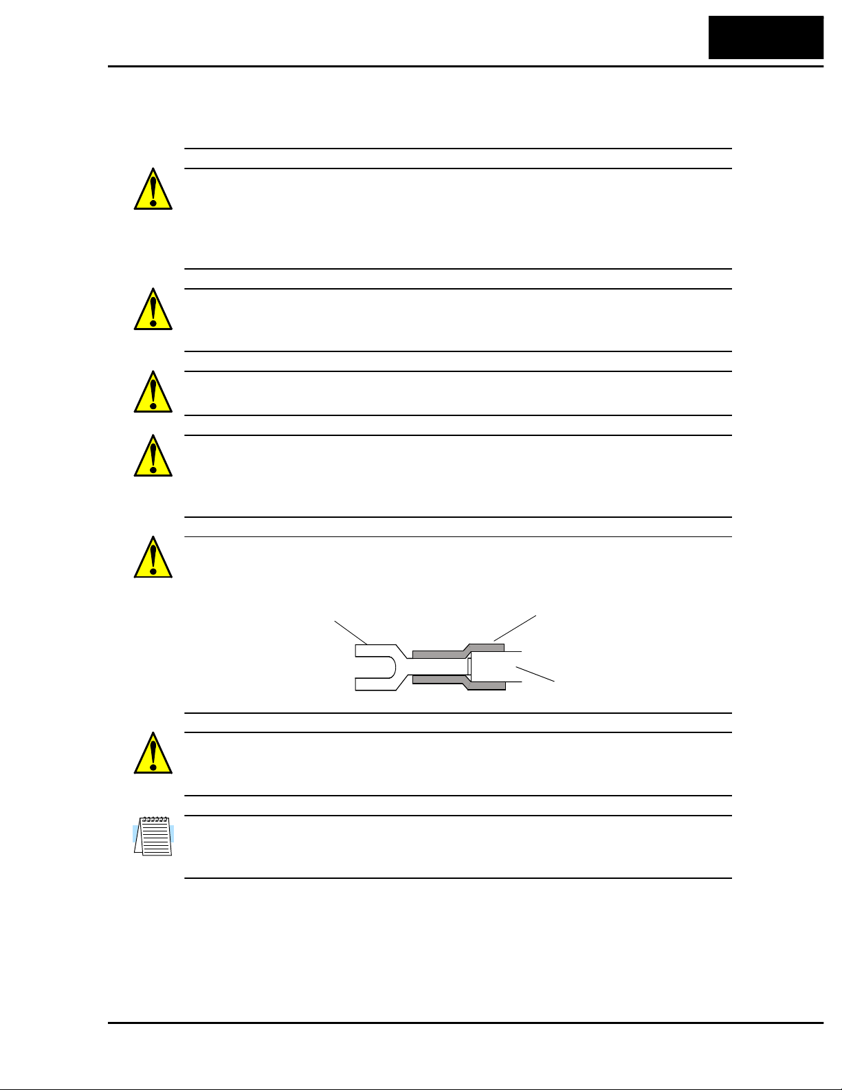
CAUTION: Connection to field wiring terminals must be reliably fixed having two
independent means of mechanical support. Using a termination with cable support
(figure below), or strain relief, cable clamp, etc.
CAUTION: A double-pole disconnection device must be fitted to the incoming mains
supply close to the inverter. Additionally, a protection device meeting IEC947-1/
IEC947-3 must be fitted at this point (protection device data shown in page 2–13).
NOTE: The above instructions, together with any other requirements are highlighted in
this manual, and must be followed for continued LVD (European Low Voltage Directive)
compliance.
Terminal (spade lug) Cable support
Cable
Technologies Inc.
Toll Free: voice: 1-877-539-2542 fax: 1-800-539-2542 www.mgitech.com

iv
Precautions for EMC (Electromagnetic Compatibility)
Precautions for EMC (Electromagnetic Compatibility)
You are required to satisfy the EMC directive (89/336/EEC) when using an L100
inv erter in a European country. To satisfy the EMC directive and to comply with
standard, follow the checklist below.
WARNING: This equipment should be installed, adjusted, and serviced by qualified
personal familiar with construction and operation of the equipment and the hazards
involved. Failure to observe this precaution could result in bodily injury.
1. The power supply to L100 inverter must meet these specifications:
a. Voltage fluctuation+/- 10% or less
b. Voltage imbalance +/- 3% or less
c. Frequency variation +/- 4% or less
d. Voltage distortion THD = 10% or less
2. Installation measure:
a. Use a filter designed for L100 inverter
3. Wiring:
a. Shielded wire (screened cable) is required for motor wiring, and the length must
be less than 50 meters.
b. The carrier frequency setting must be less than 5 kHz to satisfy EMC require-
ments.
c. Separate the main circuit from the signal/process circuit wiring.
4. Environmental conditions - when using a filter, follow these guidelines:
a. Ambient temperature: -10 to 40 °C
b. Humidity: 20 to 90% RH (non-condensing)
c. Vibration: 5.9 m/sec
2
(0.6 G) 10 ~ 55Hz
d. Location: 1000 meters or less altitude, indoors (no corrosive gas or dust)
Technologies Inc.
Toll Free: voice: 1-877-539-2542 fax: 1-800-539-2542 www.mgitech.com
L100 Inverter
v
Index to Warnings and Cautions in This Manual
Installation - Cautions for Mounti ng Procedures
Wiring - Warnings for Electrical Practices and W ire Specifications
CAUTION: Be sure to install the unit on flame-resistant material
such as a steel plate. Otherwise, there is the danger of fire.
........... 2–6
CAUTION: Be sure not to place any flammable materials near the
inverter. Otherwise, there is the danger of fire.
........... 2–6
CA UTION: B e sure not to let the foreign matter enter vent openings
in the inv erter housing, such as wire clippings, spatter from welding,
metal shavings, dust, etc. Otherwise, there is the danger of fire.
........... 2–6
CAUTION: Be sure to install the inverter in a place which can bear
the weight according to the specifications in the text (Chapter 1,
Specifications Tables). Otherwise, it may fall and cause injury to per-
sonnel.
........... 2–6
CA UTION: Be sure to install the unit on a perpendicular w all which
is not subject to vibration. Otherwise, it may fall and cause injury to
personnel.
........... 2–6
CAUTION: Be sure not to install or operate an inverter which is
damaged or has missing parts. Otherwise, it may cause injury to per-
sonnel.
........... 2–6
CAUTION: Be sure to install the inverter in a well-ventilated room
which does not have direct exposure to sunlight, a tendenc y for high
temperature, high humidity or dew condensation, high lev els of dust,
corrosive gas, e xplosive gas, inflammable gas, grinding-fluid mist,
salt damage, etc. Otherwise, there is the danger of fire.
........... 2–6
WARNING: “Use 60/75°C Cu wire only” or equivalent. ......... 2–12
WARNING: “Open Type Equipment.” ......... 2–12
WARNING: “A Class 2 circuit wired with Class 1 wire” or equiva-
lent.
......... 2–12
WARNING: “Suitable for use on a circuit capable of delivering not
more than 5,000 rms symmetrical amperes, 240 V maximum.” For
models with suffix N or L.
......... 2–12
Technologies Inc.
Toll Free: voice: 1-877-539-2542 fax: 1-800-539-2542 www.mgitech.com
vi
Index to Warnings and Cautions in This Manual
Wiring - Cautions for Electrical Practices
WARNING: “Suitable for use on a circuit capable of delivering not
more than 5,000 rms symmetrical amperes, 240 V maximum.” For
models with suffix N or L.
........ 2–12
HIGH VOLTAGE: Be sure to ground the unit. Otherwise, there is a
danger of electric shock and/or fire.
........ 2–12
HIGH VOLTAGE: Wiring work shall be carried out only by quali-
fied personnel. Otherwise, there is a danger of electric shock and/or
fire.
........ 2–12
HIGH VOLTAGE: Implement wiring after checking that the power
supply is off. You may incur electric shock and/or fire.
........ 2–12
HIGH VOLTAGE: Do not connect wiring to an inverter or operate
an inverter that is not mounted according the instructions given in
this manual. Otherwise, there is a danger of electric shock and/or
injury to personnel.
........ 2–12
WARNING: Make sure the input power to the inverter is off. If the
drive has been po were d, leave it off for five minutes before continu-
ing.
........ 2–16
CAUTION: Be sure that the input voltage matches the inverter
specifications: • Single/Three phase 200 to 240 V 50/60 Hz (up to
2.2kW) • Three phase 200 to 230V 50/60Hz (abo ve 2.2kW) • Th ree
phase 380 to 460 V 50/60Hz
........ 2–14
CAUTION: Be sure not to input a single phase to a three-phase-
only type invert er. Otherwise, there is the danger of fire.
........ 2–14
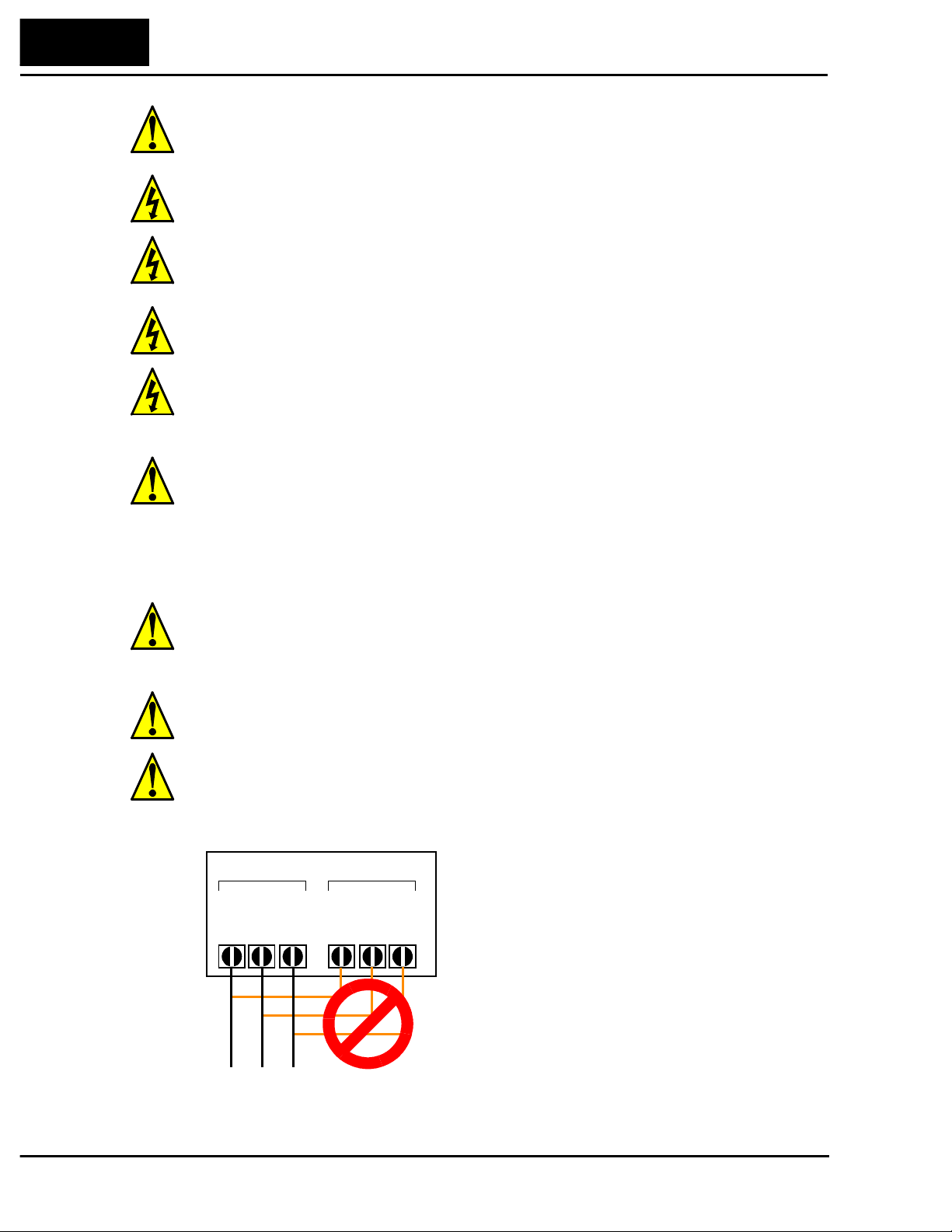
CAUTION: Be sure not to connect an AC power supply to the
output terminals. Otherwise, there is the danger of injury and/or
fire.
........ 2–14
Power Input Power Output
L1 L2 L3
T1 T2 T3
UVW
(L) (N)
NOTE:
L, N:
L1, L2, L3:
Single-phase 200 to 240V 50/60 Hz
Three-phase 200 to 240V 50/60 Hz
Three-phase 380 to 460V 50/60 Hz
Technologies Inc.
Toll Free: voice: 1-877-539-2542 fax: 1-800-539-2542 www.mgitech.com
L100 Inverter
vii
Powerup Test Caution Messa ges
CA UTION: Fasten the screws with the specified fastening torque
(see the following table). Check for any loosening of scre ws. Other-
wise, there is the danger of fire.
......... 2–15
CA UTION: Rema rks for using earth leaka ge c ircuit breakers in the
mains supply: Frequency inverters with CE-filters (RFI-filter) and
shielded (screened) motor cables have a higher leakage current
toward Earth GND. Especially at the moment of switching on this
can cause inadvertent tripping of earth leakage circuit breakers.
Because of the rectifier on the input side of the inverter there is the
possibility to stall the switch-off function through small amounts of
DC current. Please observe the following: • Use only short time-
invariant and pulse current-sensitive earth leakage circuit breakers
with higher trigger current. • Other components should be secured
with separate earth leakage circuit breakers. • Earth leakage circuit
breakers in the power input wiring of an inverter are not an absolute
protection against electric shock by direct touching.
......... 2–15
CAUTION: Be sure to install a fuse in the wire for each phase of
the main power supply to the inverter. Otherwise, there is the
danger of fire.
......... 2–15
CA UTION: For motor leads, earth leakage breakers and electro-
magnetic contactors, be sure to size these components properly
(each must have the capacity for rated current and voltage). Other-
wise, there is the danger of fire.
......... 2–15
CAUTION: The heat sink fins will have a high temperature. Be
careful not to touch them. Otherwise, there is the danger of getting
burned.
......... 2–17
CAUTION: The operation of the inverter can be easily changed
from low speed to high speed. Be sure check the capability and
limitations of the motor and machine before operating the inverter.
Otherwise, there is the danger of injury.
......... 2–17
CA UTION: If you operate a motor at a frequency higher than the
inve rte r standard def ault setting (50Hz/60Hz), be sure to check the
motor and machine specifications with the re specti v e manufacturer.
Only operate the motor at elevated frequencies after getting their
approval. Otherwise, there is the danger of equipment damage.
......... 2–18
CA UTION: Check the following before and during the powerup
test. Otherwise, there is the danger of equipment damage. • Is the
shorting bar between the +1 and + terminals installed? DO NOT
power or operate the inverter if the jumper is removed. • Is the
direction of the motor correct? • Did the inverter trip during acceler-
ation or deceleration? • Were the rpm and frequency meter readings
as expected? • Were there any abnormal motor vibrations or noise?
......... 2–18
Technologies Inc.
Toll Free: voice: 1-877-539-2542 fax: 1-800-539-2542 www.mgitech.com
viii
Index to Warnings and Cautions in This Manual
Warnings for Operations and Monitoring
WARNING: Be sure to turn on the input power supply after closing
the front case. While being energized, be sure not to open the front
case. Otherwise, there is the danger of electric shock.
.......... 4–3
WARNING: Be sure not to operate the switches with wet hands.
Otherwise, there is the danger of electric shock.
.......... 4–3
WARNING: While the inv erter is ener gized, be sure not to touch
the inverter terminals even when the motor is stopped. Otherwise,
there is the danger of electric shock.
.......... 4–3
WARNING: If the Retry Mode is selected, the motor may suddenly
restart during the trip stop. Do not approach the machine (be sure to
design the machine so that safety for personnel is secure even if it
restarts.) Otherwise, it may cause injury to personnel.
.......... 4–3
WARNING: If the power supply is cut off for a s hort period of time,
the inv erter may restart operation after the po wer supply reco ve rs if
the command to operate is active. If a restart may pose danger to
personnel, so be sure to use a lock-out circuit so that it will not
restart after power recovery. Otherwise, it may cause injury to
personnel.
.......... 4–3
WARNING: The Stop Key is effective only when the Stop function
is enabled. Be sure to enable the Key separately from the
emergency stop. Otherwise, it may cause injury to personnel.
.......... 4–3
WARNING: After the operation command is given, if the alarm
reset is conducted, it will restart suddenly. Be sure to set the alarm
reset after verifying the operation command is off. Otherwise, it
may cause injury to personnel.
.......... 4–3
WARNING: Be sure not to touch the inside of the energized
inve rter or to put any conductive object into it. Otherwise, there is a
danger of electric shock and/or fire.
.......... 4–3
WARNING: When the power is turned on when the running
command is already active, the motor will suddenly start rotation
and is dangerous. Before turning the power on, confirm that the
running command is not enabled.
.......... 4–3
WARNING: When the Stop key function is disabled, pressing the
Stop key does not cancel the stop and trip.
.......... 4–3
WARNING: Be sure to provide a separate, hard-wired emergency
stop switch. When the operation command source is a digital opera-
tor, this selection is ineffective.
.......... 4–3
WARNING: If the power is turned on and the Run command is
already active, the motor starts rotation and is dangerous! Before
turning power on, confirm that the Run command is not active.
.......... 4–6
Technologies Inc.
Toll Free: voice: 1-877-539-2542 fax: 1-800-539-2542 www.mgitech.com
L100 Inverter
ix
Cautions for Operations and Monitoring
Warnings and Cautions for Troubleshooting and Maintenance
WARNING: After the Reset command is given and the alarm reset
occurs, the motor will restart suddenly if the Run command is
already active. Be sure to set the alarm reset after verifying that the
Run command is off to prevent injury to personnel.
......... 4–16
CAUTION: The heat sink fins will have a high temperature. Be
careful not to touch them. Otherwise, there is the danger of getting
burned.
........... 4 –2
CAUTION: The operation of the inverter can be easily changed
from low speed to high speed. Be sure check the capability and
limitations of the motor and machine before operating the inverter.
Otherwise, it may cause injury to personnel.
........... 4 –2
CA UTION: If you operate a motor at a frequency higher than the
inve rte r standard def ault setting (50Hz/60Hz), be sure to check the
motor and machine specifications with the re specti v e manufacturer.
Only operate the motor at elevated frequencies after getting their
approval. Otherwise, there is the danger of equipment damage.
........... 4 –2
CA UTION: It is possible to da mage the inverter or other devices in
your application if the maximum current or voltage characteristics
of a connection point are exceeded.
........... 4 –4
WARNING: Wait at least fiv e (5) minutes after turning of f the input
power supply before performing maintenance or an inspection.
Otherwise, there is the danger of electric shock.
........... 6 –2
WARNING: Make sure that only qualified personnel will perform
maintenance, inspection, and part replacement. (Before starting to
work, remove any metallic objects from your person (wristwatch,
bracelet, etc.). Be sure to use tools with insulated handles. Other-
wise, there is a danger of electric shock and/or injury to personnel.
........... 6 –2
WARNING: Neve r remo ve connectors by pulling on its wire leads
(wires for cooling fan and logic p.c.board). Otherwise, there is a
danger of fire or injury due to wire breakage.
........... 6 –2
CA UTION: When removing connectors, nev er pull the wires (wires
for the cooling fan and logic P.C. board. Otherwise, there is danger
of fire due to wire breakage and/or injury to personnel.
........... 6 –2
CAUTION: Never test the withstand voltage (HIPOT ) on the
inve rter. The inv erter has a sur ge protector be tween the ma in circuit
terminals above and the chassis ground.
......... 6–12
Technologies Inc.
Toll Free: voice: 1-877-539-2542 fax: 1-800-539-2542 www.mgitech.com
x
General Warnings and Cautions
General Warnings and Cautions
WARNING: Never modify the unit. Otherwise, there is a danger of electric shock and/
or injury.
CAUTION: Withstand voltage tests and insulation resistance tests (HIPOT) are
executed before the units are shipped, so there is no need to conduct these tests before
operation.
CAUTION: Do not attach or remove wiring or connectors when po wer is applied. Also,
do not check signals during operation.
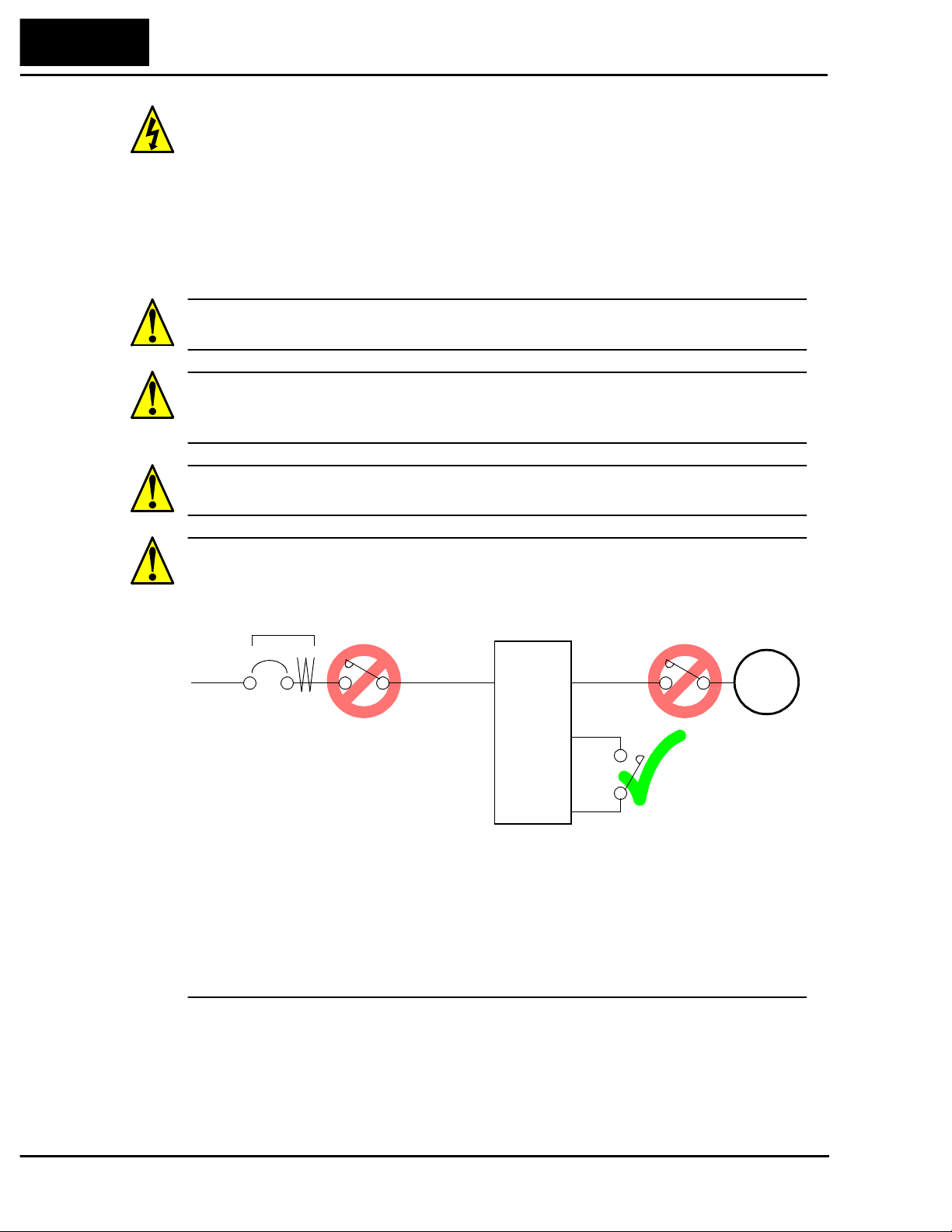
CAUTION: Do not stop operation by switching off electromagnetic contactors on the
primary or secondary sides of the inverter.
When there has been a sudden power f ailure while an operation instruction is acti ve, then
the unit may restart operation automatically after the power f ailure has ended. If there is
a possibility that such an occurrence may harm humans, then install an electromagnetic
contactor (Mgo) on the power supply side, so that the circuit does not allow automatic
restarting after the power supply recovers. If the optional remote operator is used and
the retry function has been selected, this will also cause automatic restarting when an
operation instruction is active. So, please be careful.
HIGH VOLTAGE: Be careful not to touch wiring or connector
terminals when working with the inverters and taking measure-
ments. Be sure to place the measurement circuitry above in an
insulated housing before using them.
........ 6–13
Power
Input
Inverter
L1, L2, L3
Earth leakage
breaker
U, V, W
Motor
P24
FW
Technologies Inc.
Toll Free: voice: 1-877-539-2542 fax: 1-800-539-2542 www.mgitech.com
L100 Inverter
xi
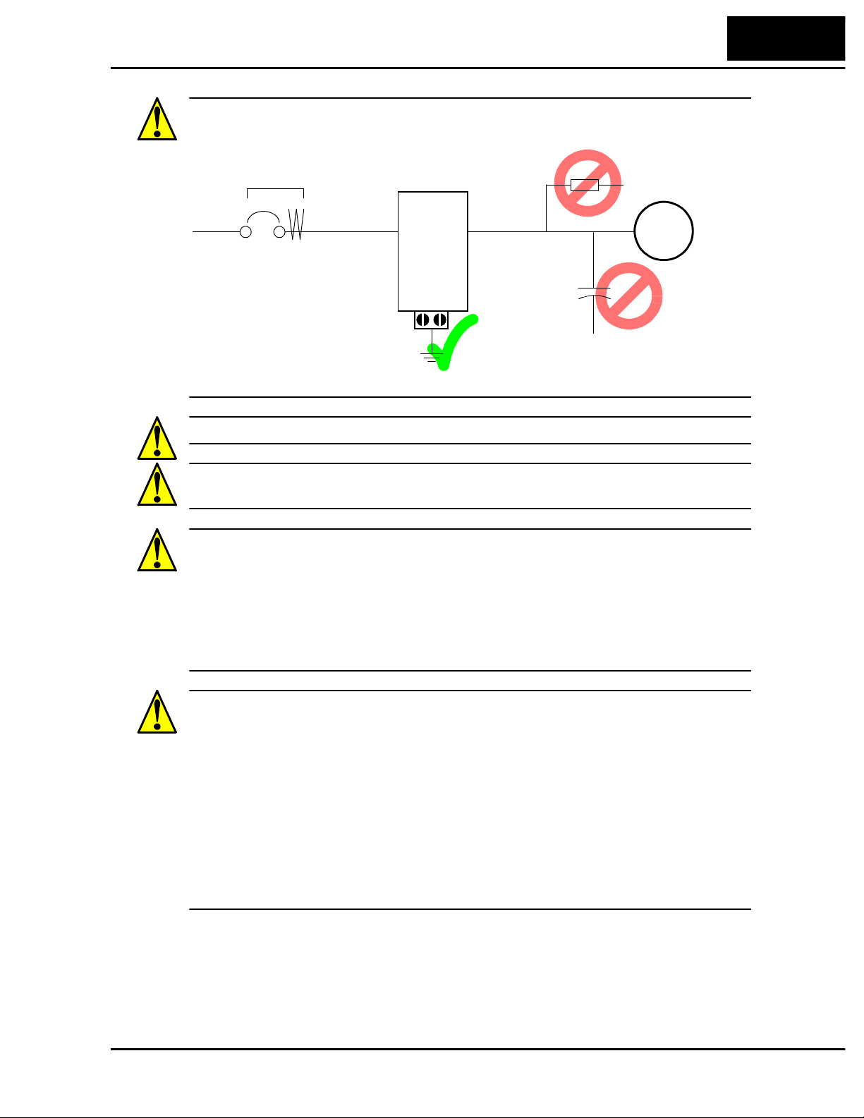
CAUTION: Do not insert leading power factor capacitors or surge absorbers between
the output terminals of the inverter and motor.
CAUTION: Be sure to connect the grounding terminal to earth ground.
CAUTION: When inspecting the unit, be sure to wait five minutes after tuning off the
power supply before opening the cover.
CAUTION: MOTOR TERMINAL SURGE VOLTAGE SUPPRESSION FILTER
(For the 400 V CLASS)
In a system using an inv er ter with the voltage control PWM system, a voltage surge
caused by the cable constants such as the cable length (especially when the distance
between the motor and inverter is 10 m or more) and cabling method may occur at the
motor terminals. A dedicated filter of the 400 V class for suppressing this voltage surge
is available. Be sure to install a filter in this situation.
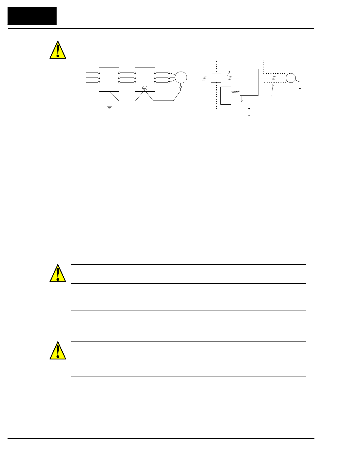
CAUTION: SUPPRESSION FOR NOISE INTERFERENCE FROM INVERTER
The inve rter uses many semiconductor switching elements such as transistor s and
IGBTs. Thus, a radio receiver or measuring instrument located near the inverter is
susceptible to noise interference.
To protect the instruments from erroneous operation due to noise interference, they
should be used well away from the inverter. It is also effective to shield the whole
inverter structure.
The addition of an EMI filter on the input side of the inverter also reduces the effect of
noise from the commercial power line on external devices.
Note that the external dispersion of noise from the power line can be minimized by
connecting an EMI filter on the primary side of inverter.
Power
Input
Inverter
L1, L2, L3
Earth leakage
breaker
U, V, W
Motor
GND lug
Surge absorbe r
Leading power
factor capacitor
Technologies Inc.
Toll Free: voice: 1-877-539-2542 fax: 1-800-539-2542 www.mgitech.com
xii
General Warnings and Cautions
CA UTION: EFFECTS OF DISTRIBUTOR LI NES ON INVERTERS
In the cases belo w in v o lving a general-purpos e inverter, a lar ge peak current fl ows on the
power supply side, sometimes destroying the converter module. Where such situations
are foreseen, or the paired equipment must be highly reliable, install an AC reactor
between the power supply and the inverter.
1. The unbalance factor of the power supply is 3% or higher.
2. The power supply capacity is at least 10 times greater than the inverter capacity (and
the power supply capacity, 500 kVA or more).
3. Abrupt power supply changes are expected.
Some examples include:
a.Several inverters are interconnected with a short bus.
b.A thyristor converter and an inverter are interconnected with a short bus.
c:An installed phase advance capacitor opens and closes.
In cases (1), (2), and (3) we recommend installing an AC reactor of 3% (at a voltage
drop at rated current) with respect to the supply voltage on the power supply side.
CAUTION: When the EEPROM error E8 occurs, be sure to confirm the setting value
again.
CAUTION: When setting b contact to the forward or reverse command [FW], [RV]
terminal, the inverter starts automatica lly. Do not set to b contact without a purpose.
General Caution
CAUTION: In all the illustrations in this manual, covers and safety devices are
occasionally removed to describe the details. While operating the product, make sure
that the covers and safety devices are placed as they were specified originally and
operate it according to the instruction manual.
EMI filter Inverter
Power
source
Motor
U
V
W
U
V
W
L1(L1)
L2
L3(N)
R1
S1
T1
R2
S2
T2
Terminal
for
grounding
Power
source
EMI
filter
Noise
Inverter
Motor
Noise
Remote
operator
Piping
(to be grounded)
or shielded wire
Ground the
frame.
Completely ground the shield made
of metal screen, enclosed panel, etc.
with as short a wire as possible.
Technologies Inc.
Toll Free: voice: 1-877-539-2542 fax: 1-800-539-2542 www.mgitech.com
L100 Inverter
xvii
Revisions
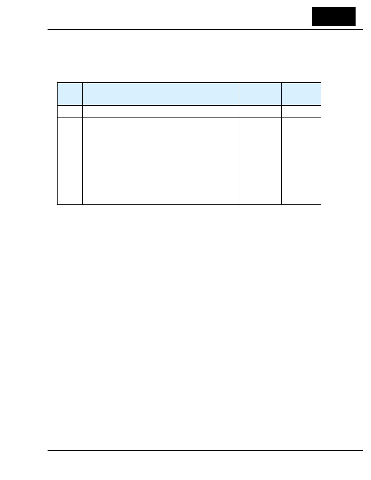
Revision History Table
No. Revision Comments Date of Issue
Operation
Manual No.
Initial Release of Manual NB576X May 1999 NB576X
1 Revision A
Pages 1-4 – Specs tables: added row for input curent,
changed rated input voltage tolerance, corrected dynamic
braking %torque, corrected product weight (lbs)
Page 2-8 – Corrected H dimension for -002 models
August 1999 NB576XA
Technologies Inc.
Toll Free: voice: 1-877-539-2542 fax: 1-800-539-2542 www.mgitech.com

Technologies Inc.
Toll Free: voice: 1-877-539-2542 fax: 1-800-539-2542 www.mgitech.com

Getting Started
In This Chapter.... page
— Introduction ...................................................... 2
— L100 Inverter Specifications............................. 4
— Introduction to Variable-Frequency Drives....... 7
— Frequently Asked Questions.......................... 12
1
Technologies Inc.
Toll Free: voice: 1-877-539-2542 fax: 1-800-539-2542 www.mgitech.com
Introduction
Getting S tarted
1–2
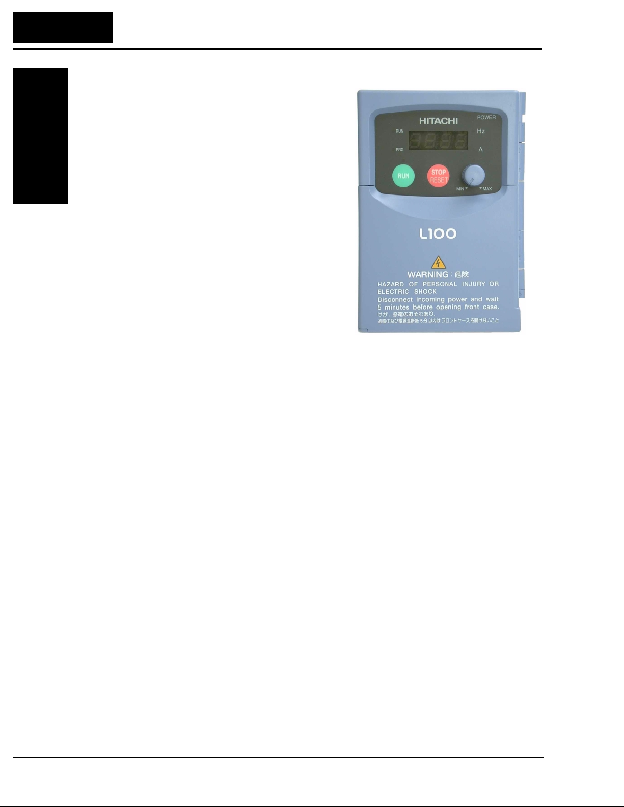
Introduction
Main Features
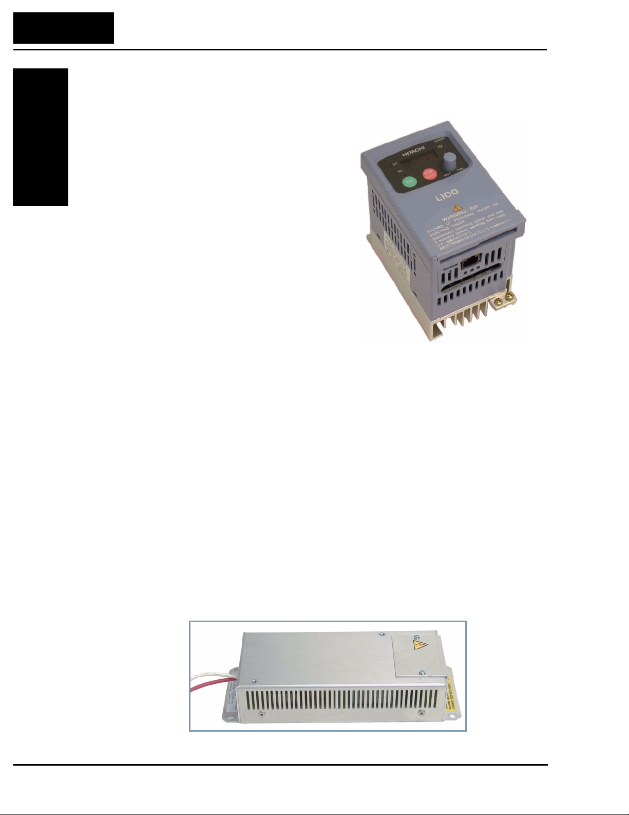
Congratulations on your purchase of an L100
Series Hitachi inverter! This inverter drive
features state-of-the-art circuitry and components
to provide high performance. The housing
footprint is exceptionally small, given the size of
the corresponding motor. The Hitachi L100
product line includes more than a dozen inverter
models to cover motor sizes from 1/4 horsepo wer
to 10 horsepower, in either 230 VAC or 460 VAC
power input versions. The main features are:
• Convenient keypad for parameter settings
• Built-in RS-422 communications interface to
allow configuration from a PC and for f ield bus
external modules.
• Sixteen programmable speed levels
• Two-step acceleration and deceleration curves
• PID control adjusts motor speed automatically to maintain a process variable value
The design in Hitachi inverters overcomes many of the traditional trade-offs between
speed, torque and efficiency. The per formance characteristics are:
• V/F (volts-per-hertz) control algorithm, selectable for either constant or reduced
torque loads
• Output frequency range from 0.5 to 360 Hz
• Continuous torque operation at 100% within a 1:10 speed range (6/60 Hz / 5/50 Hz)
without motor derating
A full line of accessories from Hitachi is available to complete your application:
• Digital remote operator keypad
• Dynamic braking unit
• Radio noise filters and EMI filters (shown below)
• CE compliance filters
• DIN rail mounting adapter (35mm rail size)
Model L100-002NFU
EMI Filter
Technologies Inc.
Toll Free: voice: 1-877-539-2542 fax: 1-800-539-2542 www.mgitech.com
L100 Inverter
Getting Started
1–3
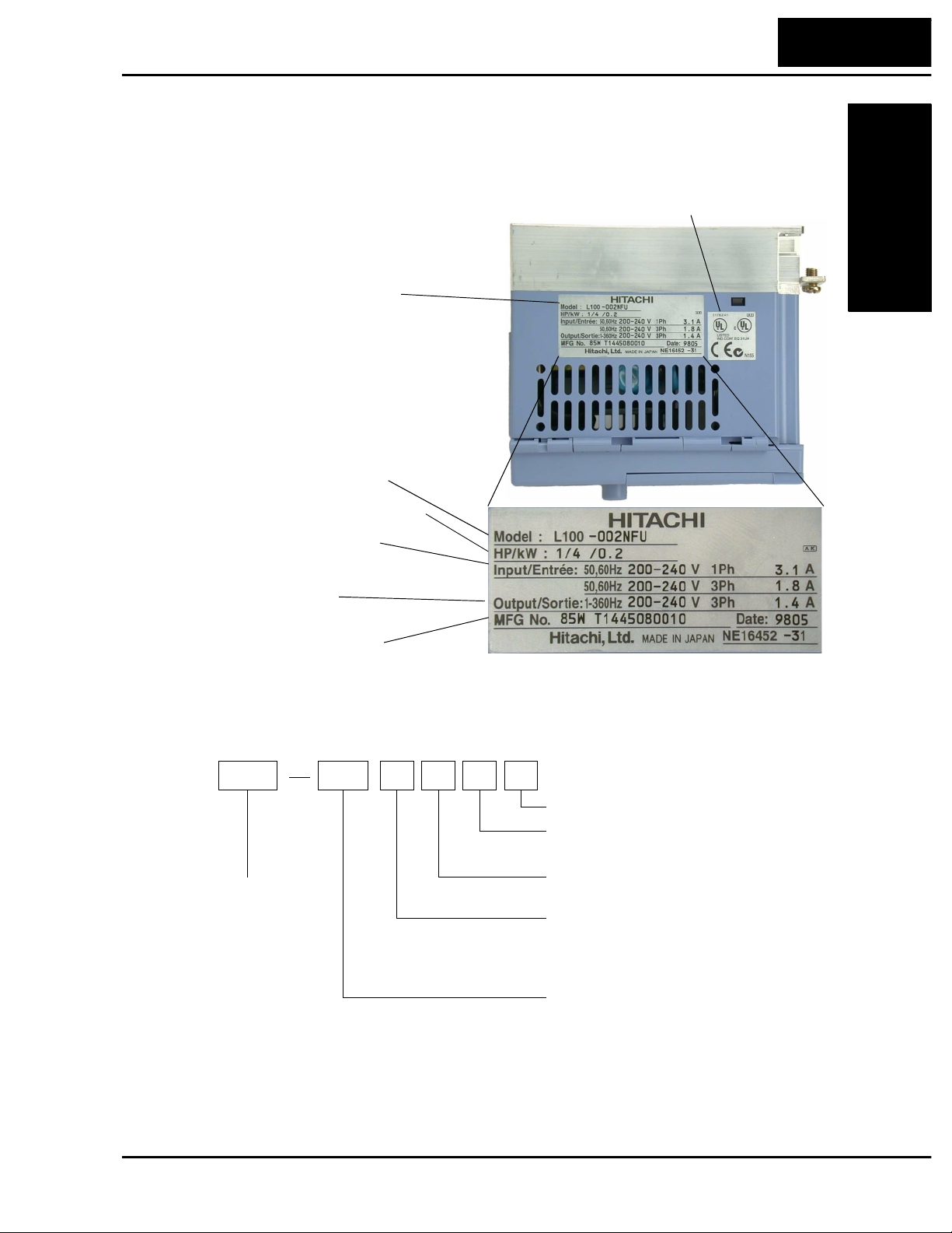
Inverter Specifications Label
The Hitachi L100 inverters have product labe ls located on the right side of the housing,
as pictured below. Be sure to verify that the specifications on the labels match your
power source, motor, and application safety requirements.
Model Number Convention
The model number for a specific in verter contains useful information about its operating
characteristics. Refer to the model number legend below:
Inv erter model number
Motor capacity for this model
Output Rating:
Frequency, voltage, current
Manufacturing codes:
Lot number, date, etc.
Specifications label
Regulatory agency approvals
Power Input Rating:
frequency, voltage, phase, current
L100 004 H F U 5
Version number (_, 1, 2, ...)
Restricted distribution:
E=Europe, U=USA
Input voltage:
N = single or three-phase 200V class
H = three-phase 400V class
L = three phase only, 200V class
Applicable motor capacity in kW
001 = 0.1 kW
002 = 0.2 kW
004 = 0.4 kW
005 = 0.55 kW
007 = 0.75 kW
011 = 1.1 kW
015 = 1.5 kW
022 = 2.2 kW
030 = 3.0 kW
037 = 3.7 kW
040 = 4.0 kW
055 = 5.5 kW
075 = 7.5 kW
Configuration type
F = with digital operator (keypad)
Series name
Technologies Inc.
Toll Free: voice: 1-877-539-2542 fax: 1-800-539-2542 www.mgitech.com
L100 Inverter Specifications
Getting S tarted
1–4
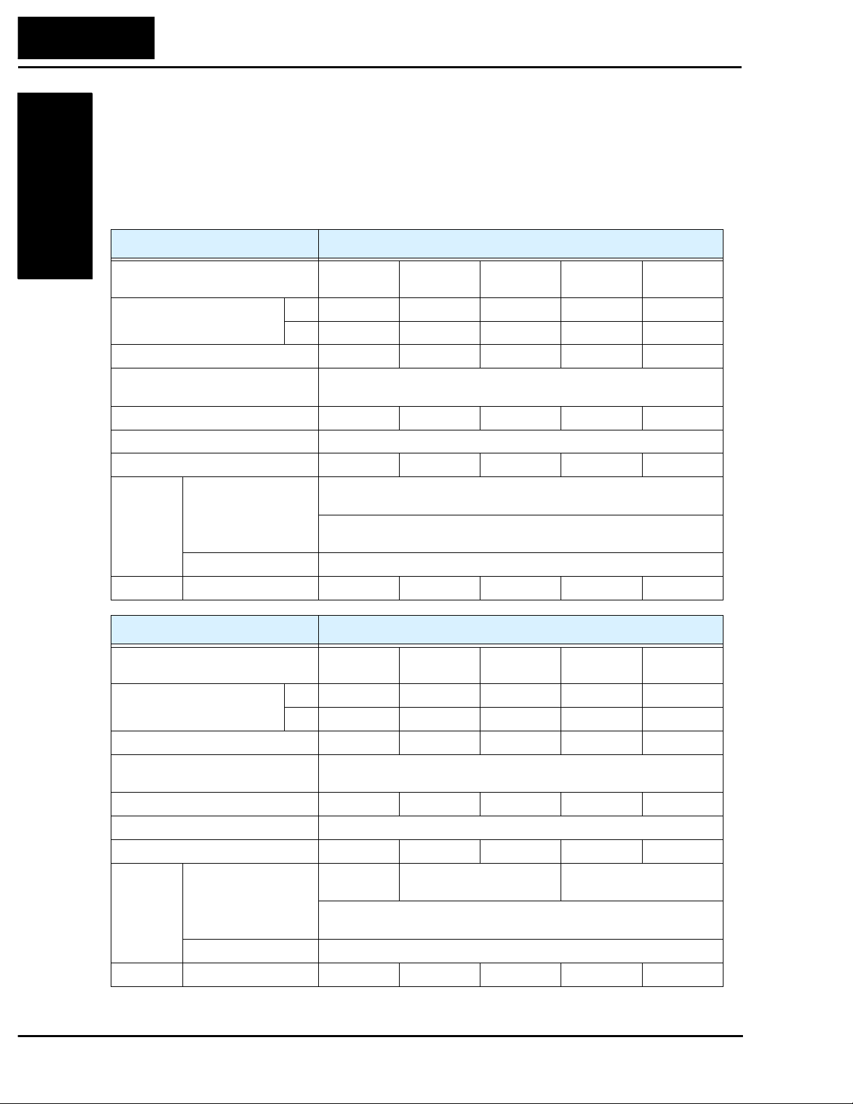
L100 Inverter Specifications
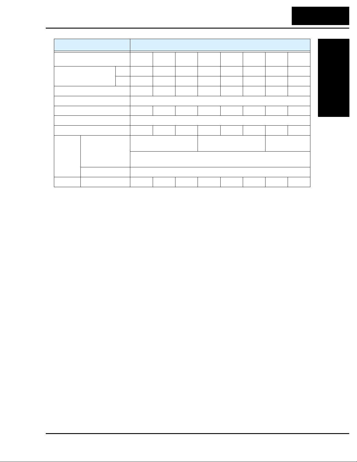
Model-specific tables for 200V and 400V class inverters
The following three tables are specific to L100 in verters for the 200V and 400V class
model groups. The table on page 1–6 gives the general specificat ions that apply to both
voltage class groups. Footnotes for all specifications tables are on the next page.
Item 200V Class Specifications
L100 inverters, 200V models 002NFE
002NFU
004NFE
004NFU
005NFE
—
007NFE
007NFU
011NFE
—
Applicable motor size *2 kW 0.2 0.4 0.55 0.75 1.1
HP 1/4 1/2 3/4 1 1 1/2
Rated capacity (240V) kVA *10 0.5 1.0 1.2 1.6 2.0
Rated input voltage 1-phase: 200 to 240V +5%/-10%, 3-phase: 200 to 230V ±10%,
50/60 Hz ±5% (037LFU, 055LFU & 075LFU 3-phase only)
Rated input current (A), (1-ph / 3-ph) 3.1 / 1.8 5.8 / 3.4 6.7 / 3.9 9.0 / 5.2 11.2 / 6.5
Rated output voltage *3 3-phase 200 to 240V (corresponding to input voltage)
Rated output current (A) 1.4 2.6 3.0 4.0 5.0
Braking Dynamic braking,
approx. % torque,
(short time, stopping
from 50 / 60 Hz) *5
100%:
≤
50Hz,
50%:
≤
60 Hz
Capacitive feedback type, dynamic braking unit and braking resistor
optional, individually installed
DC braking Variable operating frequency, time, and braking force
Weight kg / lb 0.8 / 1.9 0.8 / 1.9 1.3 / 2.9 1.3 / 2.9 2.2 / 4.8
Item 200V Class Specifications, continued
L100 inverters, 200V models 015NFE
015NFU
022NFE
022NFU
—
037LFU
—
055LFU
—
075LFU
Applicable motor size *2 kW 1.5 2.2 3.7 5.5 7.5
HP2357.510
Rated capacity (240V) kVA *10 2.9 4.1 6.3 9.6 12.7
Rated input voltage 1-phase: 200 to 240V ±10%, 3-phase: 200 to 230V ±10%,
50/60 Hz ±5% (037LFU, 055LFU & 075LFU 3-phase only)
Rated input current (A), (1-ph / 3-ph) 16.0 / 9.3 22.5 / 13.0 – / 20.0 – / 30.0 – / 40.0
Rated output voltage *3 3-phase 200 to 240V (corresponding to input voltage)
Rated output current (A) 7.1 10.0 15.9 24 32
Braking Dynamic braking,
approx. % torque,
(short time, stopping
from 50 / 60 Hz) *5
100%:
≤
50Hz
50%:
≤
60Hz
40%:
≤
50Hz
20%:
≤
60Hz
20%:
≤
50Hz
20%:
≤
60Hz
Capacitive feedback type, dynamic braking unit and braking resistor
optional, individually installed
DC braking Variable operating frequency, time, and braking force
Weight kg / lb 2.2 / 4.8 2.8 / 6.2 2.8 / 6.2 5.5 / 12.1 5.7 / 12.6
Technologies Inc.
Toll Free: voice: 1-877-539-2542 fax: 1-800-539-2542 www.mgitech.com
L100 Inverter
Getting Started
1–5
Footnotes for the preceding tables and the table on the following page:
*1: The protection method conforms to JEM 1030.
*2: The applicable motor refers to Hitachi standard 3-phase motor (4-pole). To use other
motors, care must be taken to prevent the rated motor current (50/60 Hz) from exceeding the
rated output current of the inverter.
*3: The output voltage decreases as the main supply voltage decreases (except for use of the
AVR function). In any case, the output voltage cannot exceed the input power supply
voltage.
*4: To operate the motor beyond 50/60 Hz, consult the motor manufacturer about the maximum
allowable rotation speed.
*5: The braking torque via capacitive feedback is the average deceleration torque at the shortest
deceleration (stopping from 50/60 Hz as indicated). It is not continuous regenerative braking
torque. And, the average deceleration torque varies with motor loss. This value decreases
when operating beyond 50 Hz. Note that a braking unit is not included in the inverter. If a
large regenerative torque is required, the optional regenerative braking unit should be used.
*6: The frequency command is the maximum frequency at 9.8V for input voltage 0 to 10 VDC,
or at 19.6 mA for input current 4 to 20 mA. If this characteristic is not convenient for your
application, contact your Hitachi sales representative.
*7: If operating the inverter in an ambient temperature of 40–50
°
C, reduce the carrier frequency
to 2.1 kHz, derate the output current by 80%, and remove the top housing cover. Note that
removing the top cover will nullify the NEMA rating for the inverter housing.
*8: The storage temperature refers to the short-term temperature during transport.
*9: Conforms to the test method specified in JIS C0911 (1984). For the model types excluded in
the standard specifications, contact your Hitachi sales representative .
*10:The input voltage of xxLFU is 230V.
Item 400V Class Specifications
L100 inverters, 400V models
004HFE
004HFU
007HFE
007HFU
015HFE
015HFU
022HFE
022HFU
030HFE
—
040HFE
040HFU
055HFE
055HFU
075HFE
075HFU
Applicable motor size *2 kW 0.4 0.75 1.5 2.2 3 .0 4.0 5.5 7.5
HP1/2123457.510
Rated capacity (460V) kVA *10 1.1 1.9 3.0 4.3 6.2 6.8 10.4 12.7
Rated input voltage 3-phase: 380 to 460V ±10%, 50/60 Hz ±5%
Rated input current (A) 2.0 3.3 5.0 7.0 10.0 11.0 16.5 20.0
Rated output voltage *3 3-phase: 380 to 460V (corresponding to input voltage)
Rated output current (A) 1.5 2.5 3.8 5.5 7.8 8.6 13 16
Braking Dynamic braking,
approx. % torque,
(short time, stopping
from 50 / 60 Hz) *5
100%:
≤
50Hz
50%:
≤
60Hz
40%:
≤
50Hz,
20%:
≤
60Hz
20%:
≤
50Hz
20%:
≤
60Hz
Capacitive feedback type, dynamic braking unit and braking resistor optional,
individually installed
DC braking Variable operating frequency , time, and braking force
Weight kg / lb 1.3/2.9 1.7/3.7 1.7/3.7 2.8/6.2 2.8/6.2 2.8/6.2 5.5/12.1 5.7/12.5
Technologies Inc.
Toll Free: voice: 1-877-539-2542 fax: 1-800-539-2542 www.mgitech.com
L100 Inverter Specifications
Getting S tarted
1–6
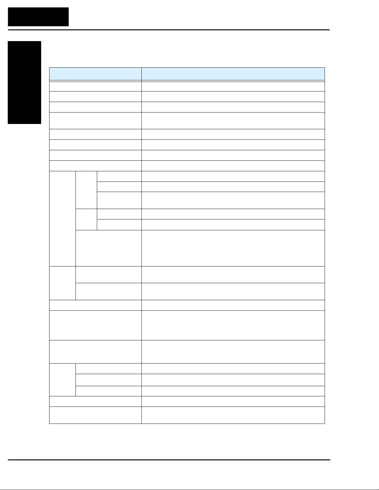
General Specifications
The following table applies to all L100 i nverters.
Item General Specifications
Protective housing *1 IP20
Control method Sine wave pulse-width modulation (PWM) control
Output frequency range *4 0.5 to 360 Hz
Frequency accuracy Digital command: 0.01% of the maximum frequency
Analog command: ±0.2% of the maximum frequency (25
°
C ± 10
°
C)
Frequency setting resolution Digital: 0.1 Hz; Analog: max. frequency/1000
Volt./Freq. characteristic V/F optionally variable, V/F control (constant torque, reduced torque)
Overload current rating 150%, 60 seconds
Acceleration/deceleration time 0.1 to 3000 sec., (linear accel/decel), second accel/decel setting available
Input
signal
Freq.
setting
Operator panel
Up and Down keys / Value settings
Potentiometer
Analog setting
External signal *6
0 to 10 VDC (input impedance 10k Ohms), 4 to 20 mA (input impedance
250 Ohms), Potentiometer (1k to 2k Ohms, 2W)
FWD/
REV
Run
Operator panel
Run/Stop (Forward/Reverse run change by command)
External signal
Forward run/stop, Reverse run/stop
Intelligent input
terminal
FW (forward run command), RV (reverse run command), CF1~CF4 (multi-
stage speed setting), JG (jog command), 2CH (2-stage accel./decel.
command), FRS (free run stop command), EXT (external trip), USP (startup
function), SFT (soft lock), AT (analog current input select signal), RS (reset),
PTC (thermal protection)
Output
signal
Intelligent output terminal RUN (run status signal), FA1,2 (frequency arrival signal), OL (ove rload
advance notice signal), OD (PID error deviation signal), AL (alarm signal)
Frequency monitor PWM output; Select analog output frequency m onitor, analog output current
monitor or digital output frequency monitor
Alarm output contact ON for inverter alarm (1C contacts, both normally open or closed avail.)
Other functions AVR function, curved accel/decel profile, upper and lower limiters, 16-stage
speed profile, fine adjustment of start frequency, carrier frequency change
(0.5 to 16 kHz) frequency jump, gain and bias setting, process jogging,
electronic thermal leve l adjustment, retry function, trip history monitor
Protective function Over-current, over-voltage, under-voltage, overload, extreme high/low
temperature, CPU error, memory error, ground fault detection at startup,
internal communication error, electronic thermal
Operat-
ing
Environ-
ment
Ambient storage humidity -10 to 50
°
C (*7) / -25 to 70
°
C (*8) / 20 to 90% humidity (non-condensing)
Vibration *9
5.9 m/s
2
(0.6G), 10 to 55 Hz
Location Altitude 1,000 m or less, indoors (no corrosive gasses or dust)
Coating color L ight purple, cooling fins in base color of aluminum
Options Remote operator unit, copy unit, cables for the units, dynamic braking unit,
braking resistor, AC reactor, DC reactor, noise fil ter, DIN rail mounting
Technologies Inc.
Toll Free: voice: 1-877-539-2542 fax: 1-800-539-2542 www.mgitech.com

L100 Inverter
Getting Started
1–7
Introduction to Variable-Frequency Drives
The Purpose of Motor Speed Control for Industry
Hitachi inv erters pro vide spee d control for 3-phase AC induction motors. You connect
AC po w er to the inverter, and connect the inverter to the motor. You’re probably familiar
with the way a light dimmer works to vary the power sent to a light bulb, and thus the
light intensity. At a basic le vel, the modern inv erter serves the same role for a motor.
Many industrial applications use AC motors of all sizes to do many different things. In
some cases, the motor connects directly to an AC power source — running at full speed
whenever it is on. Ho we ver, many applications benefit from a motor with variable speed,
in several ways:
• Energy savings - HVAC
• Need to coordinate speed with an adjacent process - textiles and printing presses
• Sensitive loads - eleva t ors, food processing, pharmaceutica ls
Over the years, industry has f ound many ways to achieve variable speed when it
benefited the process. Solutions varied from mechanical (belts and gears), hydraulic
(pumps and motors), and electrical (two-speed motor windings, etc.) While these
solutions provided some control over speed, there were unwanted side effects as well:
• Wasted energy from losses in speed-adjusting mechanisms (gearboxes, etc.)
• Wasted energy from on/off control trying to approximate an average
• Noise from belts and gears or start/stop operations
• Messy machinery with fluid leaks
• High maintenance and/or unreliable components
• Could set the speed, but acceleration and deceleration wa s still uncontrollable
• Not enough speed lev els
• Poor torque performance at low speeds
Most of the unwanted side effects came from mechanical or hydraulic machinery, and
could be solved with a purely electronic solution. But early electronic components had
reliability shortcomings due to the large currents and high voltages imposed on the
devices. Ho wever, the modern power components in use today have changed all that.
The state-of-the-art components in Hitachi drives provide all the benefits of speed
control, while overcoming the classical problems listed above.
What is an Inverter?
The term inverter and variable-frequency drive are related and somewhat interchange-
able. An electronic motor drive for an AC motor can control the motor’s speed by
varying the frequency of the power sent to the motor. F or example, a particular motor
may be designed for 60 Hz operation. We say it is a synchronous motor if its speed of
revolution is directly related to its power input frequenc y. When the motor design is
synchronous, a variable frequency drive is able to control the speed by controlling the
frequency.
Technologies Inc.
Toll Free: voice: 1-877-539-2542 fax: 1-800-539-2542 www.mgitech.com
Introduction to Variable-Frequency Drives
Getting S tarted
1–8
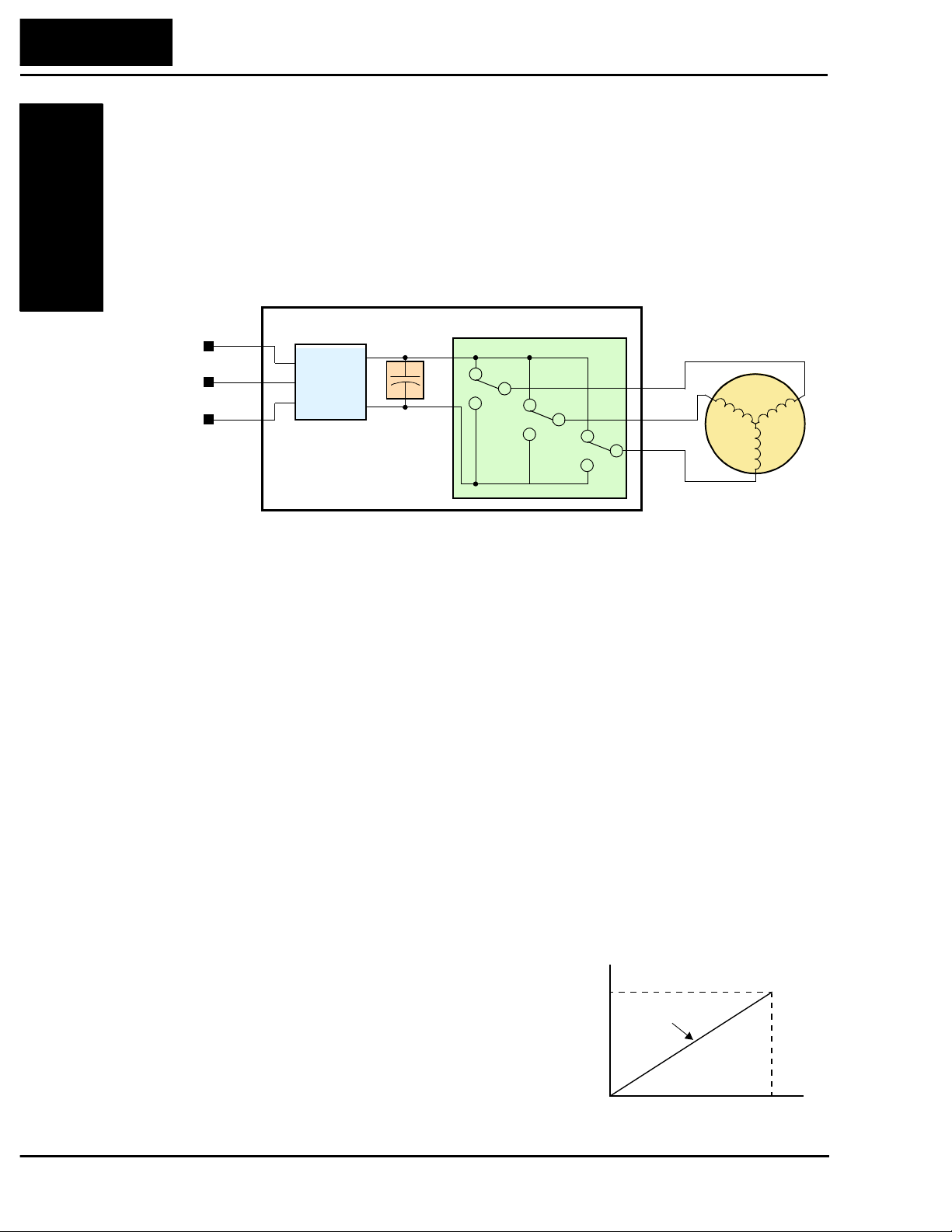
An inve rter, in general, is a device that converts DC power to AC po wer. The popular
consumer power inverter is designed for powering an AC appliance from a car battery;
put 12VDC in, and get 115VAC 50/60 Hz out, for example. The figure below sho ws ho w
the variable-frequency drive employes an internal inverter. The dri ve first converts
incoming AC po wer to DC through a rectifier c ircuit, creating a high-v oltage internal DC
bus. Then the inv e rter circuit inverts the DC back to AC again to power the motor.
However, this special inverter varies its output frequency and voltage according to the
desired motor speed.
The simplified drawing of the inverter shows three double-throw swit ches. Usually
implemented with six power transistors, outputs U/T1, V/T2, and W/T3 may switch
positively or neg ati vely. Using a commutation algorithm, the microprocessor in the drive
switches the power transistors on and of f at a very high speed to create the desired output
waveforms. The reactance of the motor windings helps smooth out the pulses.
Torque and Constant Volts/Hertz Operation
In working with industrial motors we often discuss the motor torque. That is simply the
rotational force the motor exerts at any given time. The goal of the inverter is to control
motor speed, but the L100 inverter only has direct control over the output frequenc y and
voltage. The no-load speed will be equal to the inverter output frequency minus a small
amount of slip in the motor (slip is the difference between theoretical motor speed and
actual speed). As the load increases, the slip and the delivered torque also increase . If
the inve rter can create strong motor torque over most or all of the speed range, then it is
relatively easy for the system to achieve any desired speed. Speed regulation is a
measure of the accuracy speed control, given as a percent difference from a fixed value.
The L100 delivers speed regulation (no load to full load) within 3% of the (full scale)
motor nameplate speed value.
When varying the output frequency, the inverter
drive also must vary the output voltage in propor-
tion to the frequency. It does so because of the
motor’s characteristic inductive reactance. If the
drive maintains a constant volts-per -hertz ratio, the
motor will have constant torque characteristics.
Constant torque is desirable for most applications,
because it transfers power to the load consistently
across the entire speed range.
Power
Input
Inverter
L1
Motor
L2
L3
Rectifier
Variable-frequency Drive
High-voltage
DC Bus
+
+
–
U/T1
V/T2
W/T3
Converter
100%
0
V
Output frequency
f
Constant torque
Output
voltage
100%
Technologies Inc.
Toll Free: voice: 1-877-539-2542 fax: 1-800-539-2542 www.mgitech.com

L100 Inverter
Getting Started
1–9
In verter Input and Three-Phase Power
Heavy industrial machinery often needs the additional power available from higher
voltage/current sources, and from three-phase power. The Hitachi L100 Series of inve rt-
ers includes two sub-groups: the 200V class and the 400V class inverters. The drives
described in this manual may be used in either the United States or Europe, although the
exact voltage level for commercial power may be slightly different from country to
country. Accordingly, a 200V class in verter requires (nominal) 200 to 240VAC , and a
400V class inv erter requires from 380 to 460VAC. Some 200V class inverters will accept
single-phase or three-phase power, but all 400V class inverters require a three-phase
power supply.
The common terminology for single phase power is Line (L) and Neutral (N). Three-
phase power connections are usually labeled Line 1 (L1), Line 2 (L2) and Line 2 (L3). In
any case, the power source should include an earth ground connection. That ground
connection will need to connect to the inverter chassis and to the motor frame (descrip-
tion given on page 2–16).
Inverter Output to the Motor
The AC motors also use three-phase power, but they
must connect only to the in verter’s output terminals. The
output terminals are uniquely labeled (to differentiate
them from the input terminals) with the designations U/
T1, V/T2, and W/T3. This corresponds to typical motor
lead connection designations T1, T2, and T3. It is
generally not critical to connect a particular inverter
output to a particular motor lead for a new application.
The consequence of swapping any two of the three
connections is the reversal of the motor direction. For
safety reasons, you must connect the motor chassis
ground to the ground connection at the bottom of the inverter housing.
Notice the three connections to the motor do not include one marked “Neutral” or
“Return.” The motor represents a balanced “Y” impedance to the inverter, so there is no
need for a separate return. In other words, each of the three “Hot” connections serves
also as a return for the other connections, because of their phase relationship.
The Hitachi inverter is a rugged and reliable device. The intention is for the inverter to
assume the role of switching power to the motor during all normal operations. Therefore,
this manual instructs you not to switch off power to the inverter while the motor is
running (unless it is an emergency stop). Also, do not install or use cut-off switches in
the wiring from the inverter to the motor (except thermal cut-off). Of course, safety-
related devices such as fuses must be in the design to break power during a malfunction.
3-Phase
AC Motor
U/T1
V/T2
W/T3
Earth
GND
Technologies Inc.
Toll Free: voice: 1-877-539-2542 fax: 1-800-539-2542 www.mgitech.com
Introduction to Variable-Frequency Drives
Getting S tarted
1–10
Intelligent Functions and Parameters
Much of this manual is devoted to describing
how to use inverter functions and how to config-
ure inv erter parameters. The inverter is micropro-
cessor-controlled, and has many independent
functions. The microprocessor has an on-board
EEPROM for parameter storage. The inv e rter’s
front panel keypad provides access to all
functions and parameters, which you can access
through other devices as well. The general name
for all these devices is the digital operator, or
digital operator panel. Chapter 2 will show you
how to get a motor running, using a minimal set
of function commands or configuring parame-
ters.
The optional read/write programmer will let you
read and write inverter EEPROM contents from
the programmer. This feature is particularly
useful for OEMs who need to duplicate a particu-
lar inverter’s settings in many other inverters in
assembly-line fashion.
Braking
In general, braking is a force that attempts to slow or stop motor rotation. So it is associ-
ated with motor deceleration, but may also occur even when the load attempts to drive
the motor faster than the desired speed. If you need the motor and load to decelerate
quicker than their natural deceleration during coasting, we recommend installing an
optional dynamic braking unit. See pages 5–2 and 5–5 for more information on the
BRD–E2 and BRD–EZ2 braking units. The L100 inv erter sends excess motor energy
into the resistor in the dynamic braking unit to slow the motor and load. If you have a
load that tries to drive the motor continuously for some period of time, that will require a
different type of in verter with continuous regenerativ e capability. As an example,
elevator control usually requires fast acceleration and deceleration profiles, so you may
need to add a dynamic braking unit. However, an application such as running an HVAC
fan may just coast to a stop in most cases.
The inverter parameters include acceleration and deceleration, which you can program to
match the needs of the application. For a particular inverter, motor, and load, there will
be a range of practically achievable accelerations and decelerations.
Technologies Inc.
Toll Free: voice: 1-877-539-2542 fax: 1-800-539-2542 www.mgitech.com
L100 Inverter
Getting Started
1–11
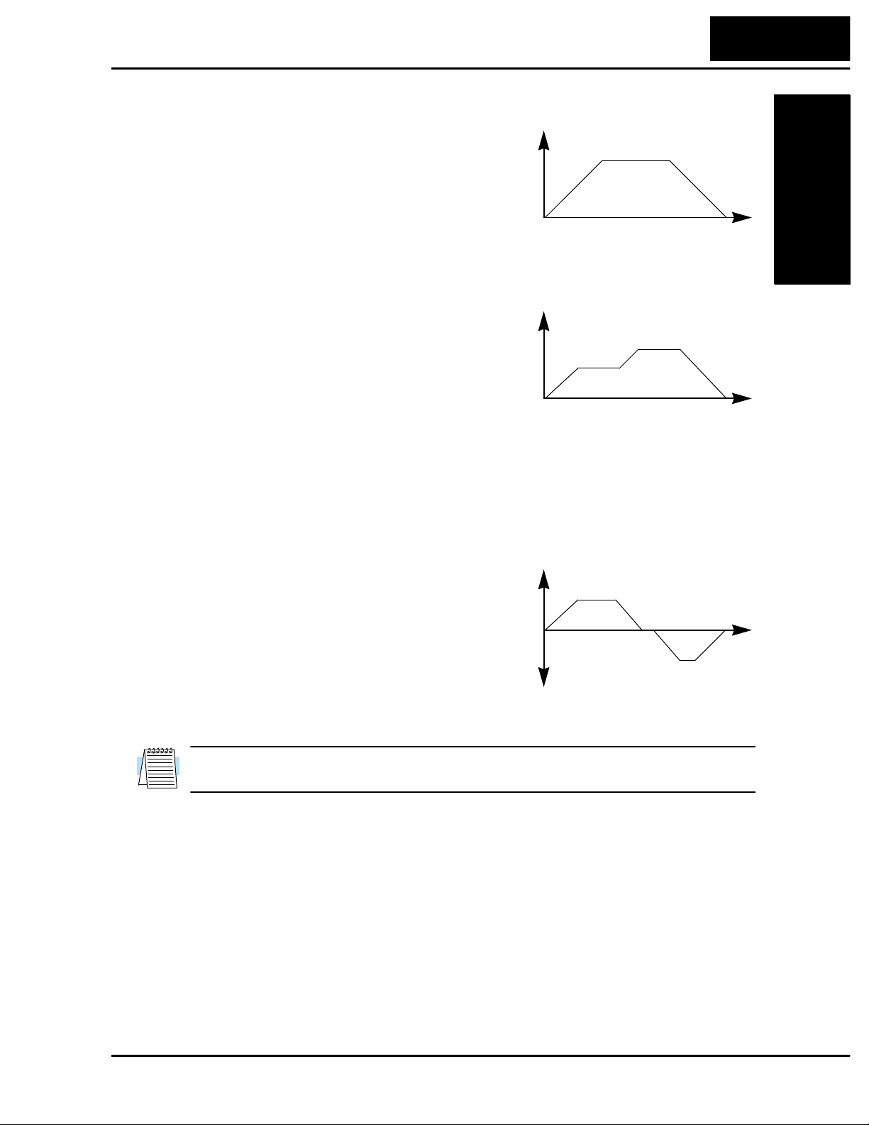
Velocity Profiles
The L100 inverter is capable of sophisticated
speed control. A graphical representation of
that capability will help you understand and
program the associated parameters. This
manual makes use of the velocity profile
graph used in industry (shown at right). In the
example, the acceleration is a ramp to a set
speed, and the deceleration is a decline to a
stop.
The L100 inverter can store up to 16 preset
speeds. And, it can apply separate accelera tion
and deceleration transitions from any prese t to
any other preset speed. For example, a motor
with a small load could use high accel/decel
values, but a heavy load will generally use
slower speed changes. A multi-speed profile
(shown at right) uses two or more preset
speeds in one motion of the load. There is no limit to the number of speed changes for
one motion; that is up to the control input to the inverter. Also note that speed can be
infinitely variable across the speed range. You can use the potentiometer control on the
keypad for manual control. The drive also acc epts analog 0-10V signals and 4-20 mA
control signals as well.
The inverter can drive the motor in either
direction. Separate FWD and REV commands
select the direction of rotation. The motion
profile example shows a forward motion
followed by a reverse motion of shorter
duration. The speed presets and analog signals
control the magnitude of the speed, while the
FWD and REV commands determine the
direction before the motion starts.
NOTE: The L100 can move loads in both directions. However, it is not designed for use
in servo-type applications that use a bipolar velocity signal which determines direction.
Speed
Time
DecelAccel
Velocity Profile
Fixed speed
Speed
Time
Multi-speed Profile
Speed 1
Speed 2
Speed
Time
Bi-directional Profile
Forward move
Reverse move
Technologies Inc.
Toll Free: voice: 1-877-539-2542 fax: 1-800-539-2542 www.mgitech.com

Frequently Asked Questions
Getting S tarted
1–12
Frequently Asked Questions
Q. What is the main advantage in using an inverter to drive a motor, compared to
alternative solutions?
A. An inverter can vary the motor speed with v ery little loss of eff iciency, unlike
mechanical or hydraulic speed control solutions. The resulting energy
savings usually pays for the inverter in a relatively short time.
Q. The term “inverter” is a little confusing, since we also use “drive” and “amplifier”
to describe the electronic unit that controls a motor. What does “inverter” mean?
A. The terms inverter, drive, and amplifier are used somewha t interchange ably
in industry. But there are subtle differences. A drive can refer to the motor,
the control electronics, or both. This term is used particularly when the
motor and electronics are integrated in the same housing. The term variable
speed drive can include many types of de vices – anything that has a variable
speed output, which includes the Hitachi inv erter. Amplifier more commonly
refers to a linear amplifier for servo motor control, or a stepper motor driver
IC. Finally, we use inverter to describe the Hitachi motor controller because
of the way the switching electronics alternately inverts or directly couples its
internal DC voltage bus to generate a variable AC output.
Q. Although the L100 inverter is a va riable speed drive, can I use it in a fixed-speed
application?
A. A fixed speed application usually is a result of cost-sensitivity or negligible
benefits if variable speed were used (consumer products are examples). In
those cases, the power source connects directly to the motor (no special driv e
needed). Howe ver, using a variable speed driv e can benefit many type of
industrial and commercial motor applications, by providing controlled accel-
eration and deceleration, high torque at low speeds, and energy savings over
alternative solutions.
Q. Can I use an inverter and AC induction motor in a positioning application?
A. That depends on the required precision, and the slowest speed the motor will
must turn and still deliver torque. If you set the torque boost, the L100 can
develop starting torque at 100% of its rating. However, DO NOT use an
inv erter if you need the motor to stop and hold the load position without the
aid of a mechanical brake (use a servo or stepper motion control system).
Q. Does the optional digital operator interface or the PC software (DOP Plus) provide
features beyond what is available from the keypad on the unit?
A. Yes. However, note first that the same set of parameters and functions are
equally accessible from either the unit’s keypad or from remote devices. The
DOP Plus PC software lets you save or load in verter configurations to or
from a disk file. And, the hand-held digital operator provides hard-wired
terminals, a safety requirement for some installations.
Technologies Inc.
Toll Free: voice: 1-877-539-2542 fax: 1-800-539-2542 www.mgitech.com

L100 Inverter
Getting Started
1–13
Q. Why does the manual or other documentation use terminology such as “200V
class” instead of naming the actual voltage, such as “230 VAC?”
A. A speci fic inverter model is set at the factory to work across a voltage range
particular to the destination country for that model. The model specifications
are on the label on the side of the inverter. A European 200V class inverter
(“EU” marking) has different parameter settings than a USA 200V class
inverter (“US” marking). The initialization procedure (see page 6–8) can set
up the inverter for European or US commercial voltage ranges.
Q. Why is there not a 100V class version of the L100 inv erter , so it would work with a
USA 115VAC power source, for example?
A. A 100V version of the L100 may be available in the future. However, most
industrial, commercial, or heavy appliance applications use 230VAC in the
USA. Also, a built-in advantage is that using the higher voltage means less
current to deliver the same amount of power. This allows you to use smaller
diameter (and less expensive) wire for power and motor wiring.
Q. I live in a country where the domestic utility power is 115 VAC. Is there a way to
conveniently access a 230 VAC power source for a test bench to develop a motor
application?
A. A 1:2 step-up transformer is available from a number of sources (check your
local electrical supply house). The transformer will be designed to develop
230 VAC from 115 VAC, for example. Be s ure the power output rating (kW)
of the transformer is greater than 1.73 times the three-phase current of the
motor you intend to power . We recommend doing this for motors 1/2 horse-
power or smaller , with small loads. F or 400 V class in v erters, we recommend
only using a utility power source of the correct voltage.
Q. Some models of Hitachi inverters will accept either single phase or three-phase
power input. How do I know which input power type to use?
A. If three-phase power is conveniently available for your application, we
recommend using that (the in v erter can develop its three-phase output power
most eff iciently from three-phase input power). In the absence of three-phase
power, you can use a single-phase power source with slightly less efficiency
but the power output rating is the same for N models (single or three-phase).
Q. If I decide to use single-phase input power for the inverter, can I also use a single-
phase motor?
A. No. All Hitachi inverters dev elop a v ariable three-phase output, requiring the
use of a three-phase AC induction motor.
Q. Why doesn’t the motor have a neutral connection as a return to the inverter?
A. T h e motor theoretically represents a “balanced Y” load if all three stator
windings have the same impedance. The Y connection allows each of the
three wires to alternately serve as input or return on alternate half-cycles.
Q. Does the motor need a chassis ground connection?
A. Yes, for several reasons. This is for protection in the event of a short in the
motor that puts a live voltage on its housing. Motors and other components
Technologies Inc.
Toll Free: voice: 1-877-539-2542 fax: 1-800-539-2542 www.mgitech.com
 Loading...