


TABLE OF CONTENTS
iHITACHI
PROJECTION COLOR TV
46UX24B/25K |
60SX12B/13K |
50UX26B/27K |
50SX8B |
OPERATING GUIDE
1

TABLE OF CONTENTS
TABLE OF CONTENTS
TABLE OF CONTENTS............................................................................................................................ |
2 |
IMPORTANT.............................................................................................................................................. |
3 |
SAFETY TIPS............................................................................................................................................. |
5 |
PICTURE CAUTIONS............................................................................................................................. |
10 |
ACCESSORIES ........................................................................................................................................ |
11 |
REMOTE CONTROL BATTERY INSTALLATION AND REPLACEMENT ............................... |
11 |
HOW TO SET UP YOUR NEW HITACHI PROJECTION TV.............................................................. |
12 |
HOOK-UP CABLES AND CONNECTORS ........................................................................................... |
14 |
ANTENNA CONNECTIONS TO REAR JACK PANEL................................................................. |
14 |
FRONT PANEL CONTROLS.................................................................................................................. |
16 |
MENU/EXIT BUTTON ................................................................................................................... |
16 |
INPUT selector................................................................................................................................ |
16 |
VOLUME level ................................................................................................................................ |
16 |
FRONT PANEL JACKS AND CONNECTIONS.................................................................................... |
18 |
REAR PANEL JACKS ............................................................................................................................. |
19 |
REAR PANEL CONNECTIONS ............................................................................................................. |
21 |
REAR SPEAKER TERMINAL CONNECTION..................................................................................... |
22 |
TIPS ON REAR PANEL CONNECTIONS...................................................................................... |
23 |
AUDIO SYSTEM SETUP........................................................................................................................ |
24 |
THE GENIUS REMOTE CONTROL (CLU-952MP) ............................................................................. |
25 |
MULTI-PAGE WINDOWS...................................................................................................................... |
26 |
HOW TO USE THE GENIUS REMOTE TO CONTROL YOUR TV.................................................... |
27 |
PICTURE-IN-PICTURE (PIP) ................................................................................................................. |
30 |
USING THE REMOTE TO CONTROL VCR FUNCTIONS.................................................................. |
35 |
USING THE REMOTE TO CONTROL CABLE BOX/SATELLITE FUNCTIONS............................. |
36 |
USING THE REMOTE TO CONTROL AUDIO EQUIPMENT FUNCTIONS..................................... |
37 |
AUDIO, CABLE/SATELLITE, AND VCR CODES............................................................................... |
38 |
ULTRATEC OSD..................................................................................................................................... |
46 |
INITIAL SETUP....................................................................................................................................... |
49 |
CUSTOMIZE ............................................................................................................................................ |
57 |
VIDEO SETTINGS................................................................................................................................... |
65 |
AUDIO SETTINGS .................................................................................................................................. |
67 |
HOME THEATER.................................................................................................................................... |
70 |
INFO. CENTER........................................................................................................................................ |
74 |
CARE OF YOUR HITACHI PROJECTION TV AND YOUR REMOTE CONTROL.......................... |
77 |
RECEPTION PROBLEMS....................................................................................................................... |
78 |
CHECK HERE BEFORE CALLING FOR SERVICE............................................................................. |
79 |
SPECIFICATIONS ................................................................................................................................... |
80 |
2
IMPORTANT
IMPORTANT
Follow all warnings and instructions marked on this television receiver.
CAUTION: TO REDUCE THE RISK OF ELECTRIC SHOCK,
DO NOT REMOVE COVER (OR BACK).
NO USER-SERVICEABLE PARTS INSIDE.
REFER SERVICING TO QUALIFIED SERVICE PERSONNEL.
 The lightning flash with arrowhead symbol, within an equilateral triangle, is intended to alert the user to the presence of uninsulated "dangerous voltage" within the product's enclosure that may be of sufficient magnitude to constitute a risk of electric shock to persons.
 The exclamation point within an equilateral triangle is intended to alert the user to the presence of important operating and maintenance (servicing) instructions in the literature accompanying the appliance.
WARNING:
TO PREVENT FIRE OR SHOCK HAZARD, DO NOT EXPOSE THIS TELEVISION SYSTEM TO RAIN OR MOISTURE.
NOTE: There are no user serviceable parts inside the receiver.
Model number and serial number are indicated on the back side of the
set.
POWER SOURCE:
This projection color TV is designed to operate on 120 volts 60 Hz, AC household current.
Insert power cord into a 120 volt 60 Hz outlet.
TO PREVENT ELECTRIC SHOCK, DO NOT USE THE TELEVISION'S PLUG WITH AN EXTENSION CORD, RECEPTACLE, OR OTHER OUTLET UNLESS THE BLADES AND GROUND TERMINAL CAN BE FULLY INSERTED TO PREVENT BLADE EXPOSURE. NEVER CONNECT THE TV TO 50 Hz, DIRECT CURRENT, OR ANYTHING OTHER THAN THE SPECIFIED VOLTAGE.
3
IMPORTANT
NOTE: This television receiver will display television closed captioning ( or
or  ), in accordance with paragraph 15, 119 of the FCC rules.
 CAUTION: Never remove the back cover of the set as this can expose you to very high voltages and other hazards. If the set does not operate properly, unplug the set and call your dealer or service shop.
4
SAFETY TIPS
SAFETY TIPS
IMPORTANT SAFEGUARDS
SAFETY POINTS YOU SHOULD KNOW ABOUT
YOUR HITACHI TELEVISION RECEIVER
CAUTION:
*Read all of these instructions.
*Save these instructions for later use.
*Follow all warnings and instructions marked on the television receiver.
Our reputation has been built on the quality, performance, and ease of service of HITACHI television receivers.
Safety is also foremost in our minds in the design of these units. To help you operate these products properly, this section illustrates safety tips which will be of benefit to you. Please read it carefully and apply the knowledge you Obtain from it to the proper operation of your
HITACHI television receiver.
Please fill out your warranty card at once and mail it to HITACHI. This will enable HITACHI to notify you promptly in the improbable event that a safety problem should be discovered in your model of product.
FOR YOUR PERSONAL SAFETY
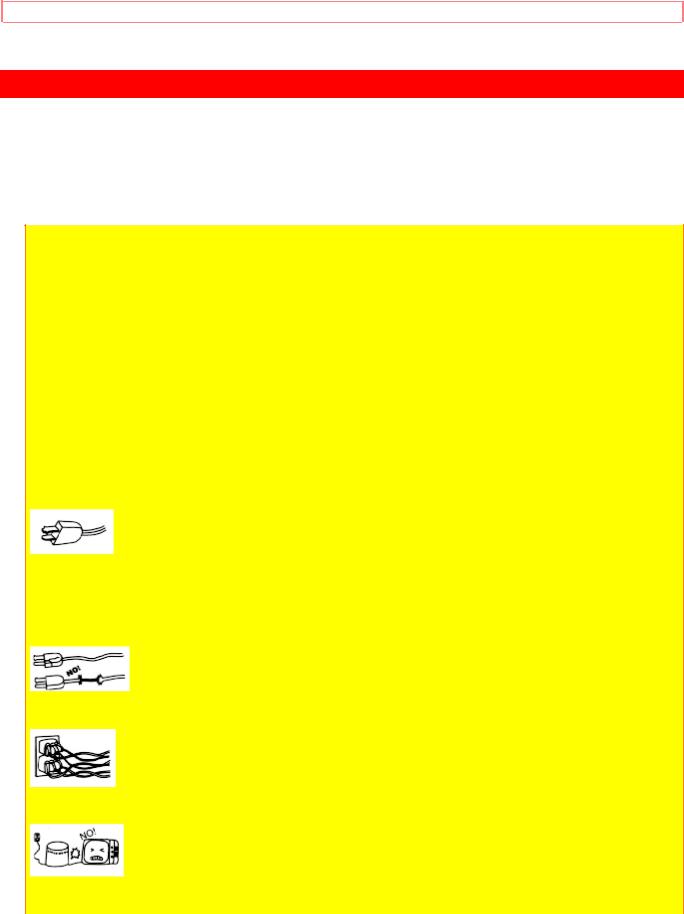
1 This television set is equipped with a polarized alternating-current line plug (a plug having one blade wider than the other). This plug will fit into the power outlet only one way. This is a safety feature. If you are unable to insert the plug fully into the outlet, try reversing the plug. If the plug should still fail to fit, contact your electrician to replace your obsolete outlet. Do not defeat the safety purpose of the polarized plug.
2 When the power cord or plug is damaged or frayed, unplug this television set from the wall outlet and refer servicing to qualified service personnel.
3 Do not overload wall outlets and extension cords as this can result in fire or electric shock.
4 Do not allow anything to rest on or roll over the power cord, and do not place the TV where the
5
SAFETY TIPS
power cord is subject to traffic or abuse. This may result in a shock or fire hazard.
5 Do not attempt to service this television set yourself as opening or removing covers may expose you to dangerous voltage or other hazards. Refer all servicing to qualified service personnel.
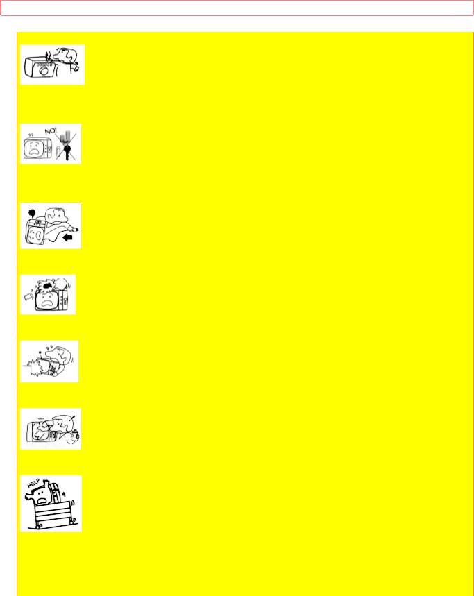
6 Never push objects of any kind into this television set through cabinet slots as they may touch dangerous voltage points or short out parts that could result in a fire or electric shock. Never spill liquid of any kind on the television set.
7 If the television set has been dropped or the cabinet has been damaged, unplug this television set from the wall outlet and refer servicing to qualified service personnel.
8 If liquid has been spilled into this television set, unplug it from the wall outlet and refer service to qualified service personnel.
9 Do not subject your television set to impact of any kind. Be particularly careful not to damage the picture tube surface.
10 Unplug this television set from the wall outlet before cleaning. Do not use liquid cleaners or aerosol cleaners. Use a damp cloth for cleaning.
11-1 Do not place this television set on an unstable cart, stand, or table. The television set may fall, causing serious injury to a child or an adult, and serious damage to the appliance.
Use only with a cart or stand recommended by the manufacturer, or sold with the television set. Wall or shelf mounting should follow the manufacturer's instructions, and should use a mounting kit approved by the manufacturer.
6
SAFETY TIPS
11-2 An appliance and cart combination should be moved with care. Quick stops, excessive force, and uneven surfaces may cause the appliance and cart combination to overturn.
PROTECTION AND LOCATION OF YOUR SET
12 Do not use this television set near water, for example, near a bathtub, washbowl, kitchen sink, or laundry tub, in a wet basement, or near a swimming pool, etc.
Never expose the set to rain or water. If the set has been exposed to rain or water, unplug the set from the wall outlet and refer servicing personnel.
13 Choose a place where light (artificial or sunlight) does not shine directly on the screen.
14 Avoid dusty places, since accumulated dust inside the chassis may cause failure of the set when high humidity persists.
15 The set has slots, or openings in the cabinet for ventilation purposes, to provide reliable operation of the receiver, and to protect from overheating. These openings must not be blocked or covered.
Never cover the slots or openings with cloth or other material.
Never block the bottom ventilation slots of the set by placing it on a bed, sofa, rug, etc.
Never place the set near or over a radiator or heat register.
Never place the set in a "built-in" enclosure, unless proper ventilation provided.
PROTECTION AND LOCATION OF YOUR SET
16-1 If an outside antenna is connected to the television set, be sure the antenna system is
7
SAFETY TIPS
protected against voltage surges and built up static charges, Section 810 of the National
Electrical Code, NFPA No. 70-1975, provides information with respect to proper grounding of the mast and supporting structure, grounding of the lead-in wire to an antenna discharge unit, size of grounding conductors, location of antenna discharge unit, connection to grounding electrode, and requirements for the grounding electrode.
Click to see antenna grounding diagram.
16-2 Note to CATV system installer: (Only for the television set with CATV reception) This reminder is provided to call the CATV system installer's attention to Article 820-40 of the NEC that provides guidelines for proper grounding and, in particular, specifies that the cable ground shall be connected to the grounding system of the building, as close to the point of cable entry as practical.
17 An outside antenna system should not be located in the vicinity of overhead power lines or other electrical lights or power circuits, or where it can fall into such power lines or circuits. When installing an outside antenna system, extreme care should be taken to keep from touching such power lines or circuits as contact with them might be fatal.
18 For added protection for this television set during a lightning storm, or when it is left unattended and unused for long periods of time, unplug it from the wall outlet and disconnect the antenna. This will prevent damage due to lightning and power-line surges.
OPERATION OF YOUR SET
19 This television set should be operated only from the type of power source indicated on the marking label. If you are not sure of the type of power supply at your home, consult your television dealer or local power company. For television sets designed to operate from battery power, refer to the operating instructions.
20 If the television set does not operate normally by following the operating instructions, unplug this set television set from the wall outlet and refer servicing to qualified service personnel. Adjust only those controls that are covered in the operating instructions as improper adjustment of other controls may result in damage and will often require extensive work by a qualified technician to restore the television set to normal operation.
8
SAFETY TIPS
21 When going on a holiday: If your television set is to remain unused for a period of time, turn the television set "off" and unplug it from the wall outlet.
IF THIS SET DOES NOT OPERATE PROPERLY
22 If you are unable to restore normal operation by following the detailed procedure in your operating instructions, do not attempt any further adjustment. Unplug the set and call your dealer or service technician.
23 Whenever the television set is damaged or fails, or a distinct change in performance indicates a need for service, unplug the set and have it checked by a professional service technician.
24 It is normal for some TV sets to make occasional snapping or popping sounds, particularly when being turned on or off. If the snapping or popping is continuous or frequent, unplug the set and consult your dealer or service technician.
FOR SERVICING AND MODIFICATION
25 Do not use attachments not recommended by the television set manufacturer as they may cause hazards.
26 When replacement parts are required, be sure the service technician has used replacement parts specified by the manufacturer that have the same characteristics as the original part. Unauthorized substitutions may result in fire, electric shock, or other hazards.
27 Upon completion of any service or repairs to the television set, ask the service technician to perform routine safety checks to determine that the television is in safe operating condition.
9

PICTURE CAUTIONS
PICTURE CAUTIONS
WARNING
Continuous on-screen displays such as video games, stock market quotations, computer generated graphics, and other fixed (non-moving) patterns can cause permanent damage to projection television receivers. Such "PATTERN BURNS" constitute misuse and are NOT COVERED by your Hitachi Factory Warranty.
When using the Picture-in-Picture function, the sub-picture should not be left permanently in one corner of the screen or a "pattern burn" may develop over a long period of time.
This projection television receiver was intended mainly for the private viewing of programs broadcast by TV stations and cable companies and programs from other video sources. Public viewing may require prior authorization from the broadcaster or owner of the video program.
10
ACCESSORIES
ACCESSORIES
Check to make sure you have the following accessories before disposing of the packing material.
1.Remote Control Unit CLU-413UI (Part No. HL00213)
2.Two "AA" size, 1.5 V batteries (For Remote Control Unit).
REMOTE CONTROL BATTERY INSTALLATION AND REPLACEMENT
1.Open the battery cover of the remote transmitter by pushing the notched part of the cover with your fingers.
2.Insert two new "AA" size batteries equivalent for the remote. When replacing old batteries, push them towards the springs and lift them out.
3.Match the (+) and (-) marks in the battery compartment.
4.Replace the cover.
BOTTOM VIEW
11

HOW TO SET UP YOUR NEW HITACHI PROJECTION TV
HOW TO SET UP YOUR NEW HITACHI PROJECTION TV
ANTENNA
Unless your TV is connected to a cable TV system or to a centralized antenna system, a good outdoor color TV antenna is recommended for the best performance. However, if you are located in an exceptionally good signal area that is free from interference, and multiple image ghosts, an indoor antenna may be sufficient.
LOCATION
Select an area where sunlight or bright indoor illumination will not fall directly on the picture screen. Also, be sure that the location selected allows free flow of air to and from the perforated back cover of the set.
To avoid cabinet warping, cabinet color changes, and increased chance of set failure, do not place the TV where temperatures can become excessively hot. For example, in direct sunlight or near a heating appliance, etc.
VIEWING
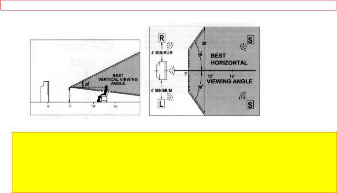
The major benefit of the HITACHI Projection Television is its large viewing screen. To see this large screen at its best, test various locations in the room to find the best spot for viewing. The drawings give several suggestions.
The best picture is seen by sitting directly in front of the TV and about 10 to 18 feet from the screen. Picture brightness decreases as the viewer moves to the left or right of the receiver.
During daylight hours, reflections from outside light may appear on the screen. If so, drapes or screens can be used to reduce the reflection or the TV can be located in a different section of the room.
If the TV's audio output will be connected to a Hi-Fi system's external speakers, the best audio performance will be obtained by placing the speakers equidistant from each side of the receiver cabinet and as close as possible to the height of the picture screen center. For best stereo separation, place the external speakers at least 4 feet from the side of the TV. Place the surround speakers to the side or behind the viewing area. Differences in room sizes and acoustical environments will require some experimentation with speaker placement for best performance.
12
HOW TO SET UP YOUR NEW HITACHI PROJECTION TV
 CAUTION: The magnetic field of external speakers may cause the TV picture to distort if the speakers are placed too close to the television. Move the speakers away from the TV until there is no picture distortion.
13
HOOK-UP CABLES AND CONNECTORS
HOOK-UP CABLES AND CONNECTORS
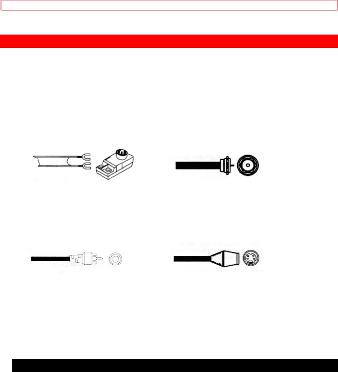
Most video/audio connections between components can be made with shielded video and audio cables that have phono connectors. For best performance, video cables should use 75-Ohm coaxial shielded wire. Cables can be purchased from most stores that sell audio/video products. Below are illustrations and names of common connectors.
Before purchasing any cables, be sure of the output and input connector types required by the various components. Also make sure the cables are the correct length.
300-Ohm Twin Lead Connector |
"F" Type 75-Ohm Coaxial Antenna |
Connector |
|
This outdoor antenna cable must be |
For connecting RF signals (antenna or |
cable TV) |
|
connected to an antenna adaptor |
to the antenna jack on the television. |
(300-Ohm to 75-Ohm). |
|
Phono Connector |
S-Video (Super Video) Connector |
Used on all standard video and audio |
This connector is used on camcorders, |
VCRs, |
|
cables which connect to inputs and |
and laser disc players with an S-Video |
feature |
|
outputs located on the Television's rear |
in place of the standard video cable to |
produce a |
|
jack panel and front control panel. |
high-quality picture. |
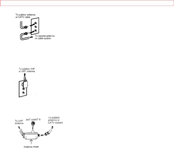
ANTENNA CONNECTIONS TO REAR JACK PANEL
VHF (75-Ohm) antenna/CATV(cable TV)
When using a 75-Ohm coaxial cable system, connect the outdoor antenna or CATV coaxial cable to the VHF/UHF 75-Ohm terminal.
14
HOOK-UP CABLES AND CONNECTORS
VHF (300-Ohm) antenna/UHF antenna
When using a 300-Ohm twin lead from an outdoor antenna, connect the VHF or UHF antenna leads to screws of the VHF or UHF adaptor. Plug the adaptor into the antenna terminal on the TV.
When both VHF and UHF antennas are connected
Attach an optional antenna cable mixer to the TV antenna terminal, and connect the cables to the antenna mixer. Consult your dealer or service store for the antenna mixer.
15

FRONT PANEL CONTROLS
FRONT PANEL CONTROLS
Click to see front panel diagram.
MENU/EXIT BUTTON
This button allows you to enter the MENU mode without using the remote. It makes it possible to set TV features to your preference, without using the remote. This button also serves as the EXIT button when in MENU mode.
INPUT selector
Press this button to select the current antenna source, VIDEO: 1, 2, 3 or alternate antenna source. Your selection is shown in the top right corner of the screen.
VOLUME level
Press these buttons for your desired sound level. The volume level will be displayed on the TV screen. These buttons also serve as the cursor left and right buttons when in
MENU mode.
4 CHANNEL selector
Press these buttons until the desired channel appears in the top right corner of the TV screen. These buttons also serve as the cursor down and up buttons when in MENU mode.
5 POWER button
Press this button to turn the TV on or off.
6 POWER light
You will see a red light when the TV is turned on.
NOTE: Your HITACHI TV will appear to be turned "OFF" if there is no video input when VIDEO: 1, 2 or 3 is selected. Check the Power Light to make sure the TV is off when not in use.
7 AI (Artificial Intelligence) sensor
This "Artificial Intelligence" sensor will make automatic picture adjustments
8 REMOTE CONTROL sensor
Point your Remote at this area when selecting channels, adjusting volume, etc.
9 MAGIC FOCUS
Use this button to adjust your picture quality to optimum performance. (See page 40.)
10 ADJUSTMENT MODE button
16

FRONT PANEL CONTROLS
This button is for service technicians only. DO NOT press this button. If this button is accidentally pressed, please turn off your television using the front panel power button. Your TV will operate normally when you turn it on again.
11 FRONT INPUT JACKS (for VIDEO:3)
Use these audio/video jacks for a "quick" hook-up from a camcorder or VCR to instantly view your favorite show or new recording. (Press the INPUT button until VIDEO:3 appears in the top right corner of the TV screen. If you have mono sound, insert the audio cable in to the left channel jack.)
17
FRONT PANEL JACKS AND CONNECTIONS
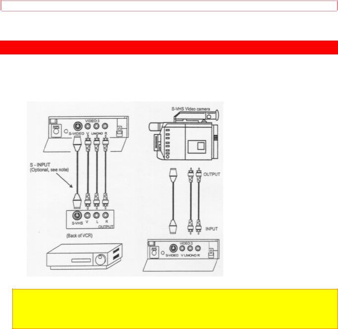
FRONT PANEL JACKS AND CONNECTIONS
The front panel jacks are provided as a convenience to allow you to easily connect a camcorder or VCR as shown in the following examples:
NOTE: Completely insert connection cord plugs when connecting to front panel jacks. If you do not, the played back picture may be abnormal. If you have a S-VHS VCR, use the
S-INPUT cable in place of the standard video cable.
If you have mono sound, insert the audio cable into the left channel jack.
18
REAR PANEL JACKS
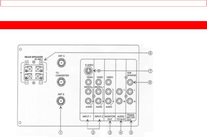
REAR PANEL JACKS
1 Antenna Input/Output
The remote control allows you to switch between two separate 75-Ohm RF antenna inputs, ANT A and ANT B. ANT A input can be displayed as a Main Picture or SubPicture. ANT B can only be displayed as a Main Picture. (ANT B cannot be displayed as a PIP sub-picture.) The antenna output labeled "TO CONVERTER" allows the ANT A connection to pass directly to a different source such as a cable box.
2 Audio/Video Inputs 1, 2
The "INPUT" button will step through each video source and antenna source input each time it is pressed. Use the audio and video inputs to connect external devices, such as
VCR's, camcorders, laser disc players, etc. (If you have mono sound, insert the audio cable into the left channel jack.)
3 Monitor Out
These jacks provide fixed audio and video signals which are used for recording.
4 Audio to Hi-Fi
These jacks provide variable audio output to a separate stereo system amplifier. With this connection, the audio to the stereo can be controlled by the televisions main volume. Use these jacks for the SURROUND Left and Right channels. (See page 15.)
5 Transmitter Out
These jacks provide variable audio output to a set of wireless speakers. They can also be used for another stereo system amplifier. With this connection, the audio can be controlled by the televisions remote control.
19

REAR PANEL JACKS
6 Rear Speaker Terminals
These terminals are used to connect external speakers, which are used for the surround sound feature. The volume level is controlled by the remote control main volume buttons and also by an independent rear volume feature found in the HOME THEATERSURROUND menu. Use speakers with 8 Ohm impedance only.
7 S-Video
Input 1 provides S-Video (Super Video) jacks for connecting equipment with S-Video output capability.
8 Sub Woofer
This jack provides variable output to a sub-woofer accessory.
20
REAR PANEL CONNECTIONS
REAR PANEL CONNECTIONS
Click to see Rear Panel Connections Illustration
Typical full feature set-up. Follow connections that pertain to your personal entertainment system.
21

REAR SPEAKER TERMINAL CONNECTION
REAR SPEAKER TERMINAL CONNECTION
Connect after turning the power to the TV OFF.
Press the Right Speaker red button and insert the positive (+) lead wire into the hole next to the button. Once the wire is in place, pull the red button back to the original position and the wire is locked into place. In the same manner, press the Right Speaker black button and insert the negative (-) lead wire. Repeat this procedure for the Left
Speaker.
 CAUTION: Do not short speaker terminals, (do no connect a wire directly across any two terminals). This could cause damage to your audio outputs or damage your TV in other ways.
 CAUTION: Do not connect speakers simultaneously to the REAR SPEAKER terminal of the Projection TV and an external amplifier. This could damage both the TV and the speakers. Your TV was designed to use 8 Ohm speakers only. Any other type may degrade the audio performance of your entertainment system.
22

REAR SPEAKER TERMINAL CONNECTION
TIPS ON REAR PANEL CONNECTIONS
The S-Video connection is provided for high performance laser discs, VCR's etc., that have this feature. Use this connection in place of the standard video connection if your device has this feature.
If your device has only one audio output (mono sound), connect it to the left audio jack on the TV.
Refer to the operating guide of your other electronic equipment for additional information on connecting your hook-up cables.
A single VCR can be used for VCR #1 and VCR #2, but note that a VCR cannot record its own video or line output (INPUT:1 in the example on page 13.) Refer to your VCR operating guide for more information on "line" input-output connections.
23

AUDIO SYSTEM SETUP
AUDIO SYSTEM SETUP
Match the numbers below to the diagram for speaker placement and refer to the table for the current surround sound requirements. (See page 56 for SURROUND functions.)
1 The television's internal speakers.
2 The television's internal center channel speaker, which is on only when the television is in SURROUND DOLBYmode.
3 These speakers are connected to a separate audio amplifier. Use the "AUDIO TO HIFI" output on the TV.
4 These speakers are connected to the Rear Speaker 8 Ohm output on the TV. 5 These speakers are controlled by a wireless speaker transmitter. Use the "TRANSMITTER OUT" output on the TV.
6 This sub woofer is connected to the "SUB WOOFER" output on the TV.
Click to see Audio System Setup Illustration
* If optional left and right speakers are connected (3), the internal speakers (1) may be turned off for better separation between the left, center, and right channels. The center channel audio will be heard from (2).
24

THE GENIUS REMOTE CONTROL (CLU-952MP)
THE GENIUS REMOTE CONTROL (CLU-952MP)
In addition to controlling the functions of your HITACHI Projection TV, the new remote is designed to operate different types of VCR's, CATV (Cable TV) converters and Audio equipment with one touch. Basic operation keys are grouped together in one area. All other controls are separated from them and arranged in MULTI-PAGE sections, with a display that can be switched to cover any of the three pages. Functions are arranged and properly categorized into windows, making operation simple when multiple functions are to be controlled.
To operate your TV, point the remote at the remote sensor of the TV and press the TV POWER button. Press the TV button and the remote will now control your TV.
To operate your VCR, point the remote at the remote sensor of the VCR. Slide the MULTI-PAGE select switch to VCR and press the VCR POWER button to turn on the
VCR power. The remote will now control your VCR. (See page 27 for instructions on how to program the remote to control your VCR.)
To operate your Cable Box, point the remote at the remote sensor of the cable box. Slide the MULTI-PAGE select switch to TV/CABLE and press the CABLE POWER button to turn on the cable box power. Press the CATV button and the remote will now control your cable box. (See page 28 for instructions on how to program the remote to control your cable box.)
To operate your Audio Equipment, point the remote at the remote sensor of the audio component you would like to operate. Slide the MULTI-PAGE select switch to AUDIO and press the button which corresponds to the component you would like to control
(AMP, CD, or TAPE). Press the AUDIO POWER button to turn on the audio component power. The remote will now control your audio equipment. (See page 29 for instructions on how to program the remote to control your audio equipment.)
Genius Remote Control Illustration
1 MULTI-PAGE select switch
This selects the button layout of the multi-page section of the remote control.
2 MULTI-PAGE buttons
These buttons change functions as shown on page 17.
3 LIGHT BUTTON
When you are in a dark room, press this button on the side of the remote to light up the buttons shown in 4. The light will stay on for about 8 seconds if the light button is not pressed again. These buttons will not appear to light if the room is too bright.
25
 Loading...