


Digital Colour Plasma Television
Model Name 42PD9700C 42PD9700N 42PD9700U
42PD9R10
55PD9700C
55PD9700N 55PD9700U
USER'S MANUAL
MANUEL UTILISATEUR
MANUALE D'USO
BEDIENUNGSANLEITUNG
MANUAL DEL USUARIO
This is the image of the model 42PD9700U.
READ THE INSTRUCTIONS INSIDE CAREFULLY.
KEEP THIS USER MANUAL FOR FUTURE REFERENCE
For future reference, record the serial number of your monitor. SERIAL NO.
This serial number is located on the rear of the monitor.
Ver. 1

ENGLISH
USER'S MANUAL
Thank you for purchasing the HITACHI Plasma Television. Please read this user manual carefully before operating this product.
To ensure proper operation, please read and follow ALL the instructions, especially the "IMPORTANT SAFETY INSTRUCTIONS" and "SAFETY PRECAUTIONS". Please keep this user manual for future reference.
Ver. 1

CONTENTS |
|
IMPORTANT SAFETY INSTRUCTIONS......... |
2 |
INTRODUCTION ........................................... |
3 |
About This Manual ................................................ |
3 |
Trademark Credits................................................. |
3 |
About Software...................................................... |
3 |
Infomation for Users Applicable in |
|
European Union Countries............. |
3 |
SAFETY PRECAUTIONS ............................... |
4 |
Important for United Kingdom ............................... |
4 |
About the Symbols ................................................ |
4 |
Cleaning and Maintenance.................................... |
7 |
ABOUT PLASMA DISPLAY PANEL................ |
8 |
Image Retention of Plasma Display Panel............ |
8 |
Common Characteristics of Plasma Display Panels... |
8 |
FEATURES.................................................... |
9 |
SUPPLIED ACCESSORIES ............................ |
9 |
COMPONENT NAMES................................. |
10 |
Main Unit ............................................................. |
10 |
Remote Control ................................................... |
11 |
PREPARATION............................................ |
12 |
Remote Control Batteries Installation.................. |
12 |
Handling the Remote Contorl.............................. |
12 |
Caution When Moving the Main Unit................... |
12 |
Safety Precaution on Main Unit Installation......... |
13 |
Anti-Tumble Measures ........................................ |
13 |
CONNECTION ............................................ |
14 |
Terminal Positions ............................................... |
14 |
Connecting Procedure......................................... |
14 |
BASIC OPERATION..................................... |
20 |
Power On/Off....................................................... |
20 |
Easy Preset......................................................... |
21 |
Volume UP/DOWN.............................................. |
22 |
Mute .................................................................... |
22 |
Input Switching to TV/AV1~5,HDMI, and RGB.... |
23 |
Input Signal Screen Display ................................ |
23 |
TV SETUP OPERATION .............................. |
24 |
How to use the On-Screen Display |
|
(OSD) system........... |
24 |
Language Menu .................................................. |
24 |
Setup Menu (TV mode)....................................... |
25 |
Setup Menu (AV mode) ....................................... |
27 |
Setup Menu (RGB mode).................................... |
28 |
Function Menu..................................................... |
30 |
Picture Menu (TV/AV mode)................................ |
32 |
Picture Menu (RGB mode).................................. |
35 |
Audio Menu ......................................................... |
37 |
Timer Menu ......................................................... |
38 |
Analogue Teletext................................................ |
39 |
DIGITAL TERRESTRIAL TELEVISION |
|
(DTT) OPERATION......... |
40 |
How to use the On-Screen Display |
|
(OSD) system...................................................... |
40 |
Changing Preset.................................................. |
41 |
Channel Selections ............................................. |
42 |
Channel Sort ....................................................... |
43 |
Channel Editing................................................... |
43 |
Utilizing the Information Tool ............................... |
44 |
Timer Programming............................................. |
46 |
Confi guring the Setting........................................ |
47 |
Common Interface............................................... |
50 |
TV Setup Menu ................................................... |
50 |
FUNCTION.................................................. |
51 |
Power Swivel....................................................... |
51 |
Size Switching..................................................... |
52 |
Multi Picture Mode............................................... |
56 |
Picture Freezing .................................................. |
60 |
Photo Input Function ........................................... |
61 |
Audio Switching................................................... |
67 |
Power Save Mode............................................... |
68 |
DVD Player / STB Selection................................ |
69 |
TROUBLESHOOTING.................................. |
70 |
When Following Messages Appear |
|
on the Screen...................................................... |
70 |
Symptom and Check List .................................... |
70 |
PRODUCT SPECIFICATIONS ...................... |
73 |
Signal Input ......................................................... |
74 |
Recommended Signal List .................................. |
75 |
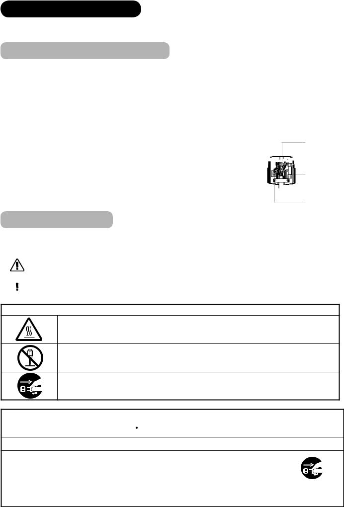
IMPORTANT SAFETY INSTRUCTIONS
 Read this instruction thoroughly.
 Retain this instruction for future reference.
 Heed all warnings and cautions to prevent possible danger.
 Follow all instructions. Improper handling could cause personal injury and/or serious damage to the unit that may shorten its service time.
 Do not block any ventilation openings.
 Install the product in accordance with the manufacture’s instructions.
 Before calling for the technical support or service technician, read “TROUBLESHOOTING” ( 70 ~ 72 ) to determine the symptoms when problems occur during installation or operation of the product.
 If serious problems happen (such as smoke or an abnormal odor from the unit), turn off the Main Power, unplug the Power Cord, and then, contact your local dealer immediately.
2

INTRODUCTION
Thank you for purchasing the HITACHI Plasma Television. We hope that you will enjoy the great performance with this product.
This Plasma Television has been designed to meet the international standards. However, it could cause personal injuries and property damage if improperly handled. In order to prevent potential danger and obtain maximum benefit from your set, please observe the following instructions when installing, operating, and cleaning the product.
Keep this manual for future reference, and record the serial number of your set in the space provided on the front cover page of this manual.
About This Manual
 The information in this manual is subject to change without notice.
 This manual has been created with extra care. In case that you have any comments or questions regarding this manual, please contact your local dealer or our Customer Service Centre.
 Before operating this set, please fully understand the prerequisite such as specifi cations or constraints of the hardware and software. We are not responsible and have no liability for any loss, damage or injury as a result of misuse.
 Reproduction, copying, use, modifi cation, and/or transmission in whole or in part of this manual are prohibited without any prior written permission.
 All other products and company names used in this manual are trademarks or registered trademarks of their respective owners.
Trademark Credits
 VGA and XGA are trademarks of International Business Machines Corporation.
 APPLE and Macintosh are registered trademarks of Apple Computer Inc.
 VESA is a registered trademark of the Video Electronics Standard Association.
 Licensed by BBE Sound, Inc. under USP5510752 and 5736897. BBE and BBE symbol are registered trademarks of BBE Sound, Inc. Manufactured under license from BBE Sound, Inc.
 WOW, SRS and ( ) symbol are trademarks of SRS Labs, Inc. WOW technology is incorporated under license from SRS Labs, Inc.
 SD Logo is a trademark.
 HDMI, the HDMI logo and High-Defi nition Multimedia Interface are trademarks or registered trademarks of HDMI Licensing LLC.
 DVB is a registered trademark of the DVB Project. This logo indicates that the product is compliant with European Digital Broadcasting.
 FREEVIEW and the FREEVIEW logo are trade marks of DTV Services Ltd and are used under license. FREEVIEW Logo © DTV Services Ltd 2002. This logo indicates that the product is set up to view digital terrestrial TV.
 The Digital logo is a Certifi cation Mark. This logo indicates that the product will work after implementation of full digital switchover.
 The "HD ready" logo is a trademark of EICTA.
Even if no special notation has been made of company or product trademarks, these trademarks have been fully respected.
About Software
You may not alter, decompile, disassemble, decrypt, or otherwise reverseengineer the Software installed in this product, which are prohibited by law.
Information for users applicable in European Union countries
This symbol on the product or on its packaging means that your electrical and electronic equipment should be disposed at the end of life separately from your household wastes. There are separate collection systems for recycling in EU.
For more information, please contact the local authority or the dealer where you purchased the product.
ENGLISH
3
SAFETY PRECAUTIONS
For your safety, please read the following precautions carefully before using this product. Improper use would cause serious personal injuries
and/or damage to your property or this product.
Important For United Kingdom
IMPORTANT FOR UNITED KINGDOM
WORDING FOR CLASS I EQUIPMENT INSTRUCTION BOOKS AND LABELS
The mains lead on this equipment is supplied with a molded plug incorporating a fuse, the value of which is indicated on the pin face of the plug. Should the fuse need to be replaced, an ASTA or BSI approved BS 1362 fuse must be used of the same rating. If the fuse cover is detachable never use the plug with the cover omitted. If a replacement fuse cover is required, ensure it is of the same colour as that visible on the pin face of the plug. Fuse covers are available from your dealer.
DO NOT cut off the mains plug from this equipment. If the plug fi tted is not suitable for the power points in your home or the cable is too short to reach a power point, then obtain an appropriate safety approved extension lead or consult your dealer.
Should it be necessary to change the mains plugs, this must be carried out by a competent person, preferably a qualified electrician.
If there is no alternative to cutting off the mains plug, ensure that you dispose of it immediately, having fi rst removed the fuse, to avoid a possible shock hazard by inadvertent connection to the mains supply.
WARNING: THIS EQUIPMENT MUST BE EARTHED IMPORTANT
The wires in the mains lead are coloured in accordance with the following code : Green and Yellow = Earth, Blue = Neutral, Brown = Live.
As these colours may not correspond with the coloured markings identifying the terminals in your plug, proceed as follows:
The wire which is coloured GREEN and YELLOW must be connected to the terminal in the plug which is marked with the letter E or by the earth symbol  or coloured GREEN or GREEN and YELLOW.
The wire coloured BLUE must be connected to the terminal marked with the letter N or coloured BLUE or BLACK. The wire coloured BROWN must be connected to the terminal marked with the letter L or coloured BROWN or RED.
Green & Yellow to Earth


 Brown to Live
Fuse

 Cord Clamp
Blue to Neutral
About the Symbols
The following are the symbols used in this manual and affi xed on the unit itself. Please fully understand the meanings of the symbols before
reading the instructions in this section.
|
|
WARNING |
Never ignore the instruction. There are risks of serious injuries or possible death to the user. |
|
|
|
|
|
|
CAUTION |
Do not ignore the instruction. There are possibilities of personal injuries and/or property damage. |
|
|
||
|
|
|
|
|
|
|
|
Other Symbols
The triangle with illustration is intended to alert the users that there are possibilities of fi re, explosion, or high
temperature if the product is handled improperly.
Each illustration within the triangle specifi es the contents in detail. (The fi gure on the left is an example.)
The circle with diagonal line and illustration indicates a prohibited action (the symbol to the left indicates that
disassembly is prohibited.)
This symbol indicates a compulsory action.
The contents will be clearly indicated in an illustration or nearby (the symbol to the left indicates that the power plug
should be disconnected from the power outlet).
 WARNING
There is a risk of fire, electric shock, or serious injury.
■Unplug the power cord immediately when serious problems occur.
Serious problems such as
 Smoke, abnormal odor or noise is emitted from the product.
 No picture, no sound or distorted picture on the display.
 Foreign objects (such as water, metals etc.) get inside the unit. Do not continue using the product under these abnormal conditions.
Turn off the Main Power, unplug the Power Cord, and contact your dealer immediately.
For your safety, never try to repair the product by yourself.
Disconnect the plug from the power outlet.
4
SAFETY PRECAUTIONS (continued)
 WARNING
There is a risk of fire, electric shock, or serious injury.
■Do not insert liquids or any foreign objects (such as metals or flammable items) inside the unit.
 In case it happens, turn off the main power, unplug the Power Cord, and contact your dealer immediately.
 Use special caution when younger children are around the unit.
■Do not remove cover, or modify the product.
High-voltage components are installed inside of the unit. Removing covers can expose you to high |
|
|
voltage, electrical shock, and other dangerous conditions. |
Do not |
|
Contact your local dealer to perform servicing such as inspection, adjustment, or repair work. |
||
disassemble |
||
|
■Do not place any objects on top of the unit.
Objects such as
 Liquid containers (vase, fi sh tank, fl owerpot, cosmetics or liquid medicine).
 If water or any liquid spill onto the unit, it may cause short-circuit and result in fi re or electrical shock.
 In case that it happens, turn off the Main Power, unplug the Power Cord, and contact your dealer immediately.
 Do not place anything heavy on top of the unit.
 Do not climb on or hang from the unit.
 Do not let your pets get on top of the unit
■Do not expose this unit to rain or moisture.
 Never use this unit in the bathroom or shower room.
 Beware when you use this product outside, especially in rainy, or snowy weather, and at the beach or waterfront.
 When the product gets wet, it could cause fi re or electrical shock.
■ Unplug this unit during lightning storm.
 To reduce the risk of electrical shock, do not touch the product when starts lightning.
■ Do not do anything that may damage the Power Cord.
 Do not damage, modify, twist, forcibly bend, heat, or pull excessively the Power Cord.
 Do not place heavy objects (including the unit itself) on top of the Power Cord.
 If the Power Cord is damaged, contact your dealer for repairs or exchange.
Disconnect the plug from the power outlet.
■ Use only with designated power supply voltage.
 To prevent the risk of fi re and electrical shock, operate this product only with the power supply voltage indicated on the unit.
■Beware not to drop or have any impact on the unit.
 Take extra care while moving the unit.
 The plasma display panel is made of glass. In case that it breaks, you may be injured with the broken pieces.
 In case that you drop the unit or the cabinet is damaged, turn off the Main Power, unplug the Power Cord and contact your local dealer immediately.
 Continuing use of the product with above conditions would cause fi re or electrical shock.
■Clean dust or metals on or around the blade of the power plug regulary.
 Continuing use of the product with above condition may cause fi re or electrical shock.
 Always unplug the Power Cord first, and clean the blades with a dry cloth.
■Do not place the unit on an unstable surface.
Unstable places such as
 Tilted surface or shaky rack, table, stand or trolly.
 If the unit falls down, it could cause personal injury.
ENGLISH
5
SAFETY PRECAUTIONS (continued)
 CAUTION
■Do not place the unit at a dusty place.
It could cause malfunction.
■Do not cover or block any ventilation holes on the product.
The monitor would overheat, and it could cause fi re or damage the product which may shorten its service life.  Install the product in accordance with the instructions in this manual.
 Do not place the unit with ventilation side down.
 Do not install the unit on the carpet or bedclothes.
 Do not cover the unit with table cloth etc.
■ Be sure to ground the earth cable correctly.
 Especially when you use Power Cord adapter, be sure to connect the earth cable to the ground terminal. Incorrect connection would cause fi re or electrical shock.
 For your safety, always make sure to unplug the Power Cord before connect or disconnect the earth cable .
Supply connect the ground wire.
■ Follow the Anti-tumble measures in this manual.
 If the unit tumbles over, there is a risk of personal injury and possible death. Also, it would damage the product seriously.
■ Do not install this product near the medical devices.
 To prevent malfunction of the medical devices, do not use this product and medical devices in the same room.
■Do not place the CRT-based television near the speakers of the Plasma Display.
 It could cause the partial discoloration or blurring of the image on a CRT-based television. Please install it away from the speakers of the unit.
■Disconnect all of the external connection cables and detach the anti-tumble measures before moving the unit.
 It may cause fi re, electrical shock, or personal injuries.
■Connect the power plug securely.
 Improper connection will cause overheating and may result in fi re.
 Do not touch the blades of the plug while connecting it to the wall socket. It could cause electrical shock.
 If the plug is not fi tted for the wall socket, contcat your dealer for replacement.
■Do not handle the Power Cord with wet hands.
 It could result in electrical shock.
■Do not pull the cord when you unplug the Power Cord.
 It may damage the cord and could result in fi re or electrical shock.
 Hold the plug when disconnecting it.
■Unplug the Power Cord when you do not intend to use the product for long periods of time.
■Handle the batteries properly.
 Improper or incorrect use of the batteries may cause corrosion or battery leakage, which could cause fi re, personal injury or damage to property.
 Use only the types of the batteries which are indicated in this manual.
 Do not insatall new batteries with used ones.
 Install the batteries correctly by following the polarity (+ and -) indications on the battery compartment.
 Do not despose of the used batteries as domestic waste. Dispose of them in accordance with the local regulations.
6
SAFETY PRECAUTIONS (continued)
PRECAUTIONS
■Do not install areas where it will be subjected to high temperatures.
It could damage the cabinet or parts of the product.
 Do not install near any heat sources such as radiators, heat registers, stoves, or other apparatus that produce heat.
 Keep the unit out of direct sunlight. It could increase the temperature of the unit and cause malfunction.
■ Viewing Advice
 The lighting of the environment in which the product is used should be appropriate. Too bright or dark environments are not good for your eyes.
 Take time to relax your eyes occasionally.
 When you use this product, view from a distance equal to 3 to 7 times the height of the screen. This is the best viewing distance in order to protect your eyes against eyestrain.
 Adjust the volume to an appropriate level, especially during the night.
■ When transporting this product:
 When the product needs to be transported due to moving or repair, use the carton box and buffer material that came with this product.
 Do not transport this product on its side. It could damage the panel glass or degrade the phosphors of the panel.
■ Keep radio away from this unit whilst in use.
This unit is designed to meet the international EMI standards due to prevent radio interference. However, the unit may generate noise in the radio.
 If the noise is heard on radio, please try the following actions.
 Adjust the direction of the radio antenna in order not to receive the interference from the unit.
 Keep the radio away from the unit.
 Use coaxial cable for the antenna.
■ About infrared communication devices:
 The infrared communication devices such as cordless microphones or cordless headphones may not operate properly around the unit. It is because of communication failure. Please note that this is not malfunction.
■When you dispose of this product at the end of its life, follow the regulations in your residential area.
 For more information, contact the local authority or the dealer where you purchased the product.
Cleaning and Maintenance
Please make sure to unplug the power cord before cleaning the unit.
■ How to clean the plasma screen panel of the unit.
 The panel surface is specially-coated to reduce the refl ection and cut infrared radiation; thus, wipe the panel with a lint-free and dry cloth in order to prevent damage to the coating.
 Do not use a chemical cloth or cleaner. Depending on the ingredients, it may cause discoloration and damage on the coating.
 Do not wipe with a hard cloth or rub hard. It may hurt the coating.
 In case of the greasy dirt such as fi ngerprint, wipe with a lint-free cloth moistened by a diluted neutral detergent solution, and then wipe with a soft and dry cloth.
 Do not use a spray cleaner. It could remove the coating or cause malfunction by entering inside of the unit.
ENGLISH
7
ABOUT PLASMA DISPLAY PANEL
Image Retention of Plasma Display Panel
The plasma display panel has one of characteristics that can result in panel image retention depending on how the plasma display is used. The following are the common reasons for and effective preventive measures against the image retention.
Characteristics of Image Retention
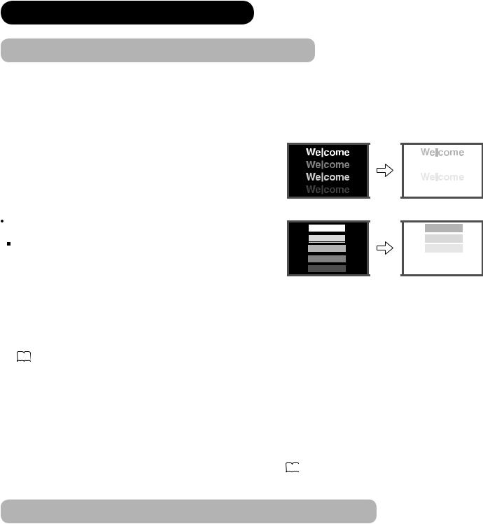
 Image retention is caused by partial degrading the phosphors due to the partial display of character and fi gure.
  For example, when the characters as shown in Fig. A are displayed
continuously for a long period of time, only the phosphors (Red/Green/ Blue) displaying the characters are degraded. Consequently, when displaying an all white image on the entire screen as shown in Fig. a, the marks remaining by the characters will show colour differences; therefore, note that it is not burnt remains of the phosphors.
The degree of image retention is proportional to the Brightness |
|
|
and Display Time for the characters and/or fi gures. |
|
|
The brighter the characters and fi gure, the more phosphor is |
|
|
degraded. As shown in Fig. B, in case of displaying images that |
|
|
have different brightness each for a long time, Fig. b shows that |
|
|
the brighter the image, the more it tends to remain. |
[Fig. B] |
[Fig. b] |
|
*The illustrations are images to explain image retention. The actual manners on the image retention vary depending on such conditions as operation time and brightness.
Method to Reduce Image Retention
 Use “Screen Wipe” or “Luminance Manager” functions on the display, which are available from Function Menu. (Refer to 30 .)
After displaying certain images such as a still image for a long time, “Screen Wipe” can be used to reduce the image retention by displaying a completely white screen for about 1~2 hours. In addition, “Luminance Manager” function works when displaying images such as TV station logos or clock displays in the corners of the screen.
 Use in combination with moving images.
Since the entire screen has relatively even degradation of the phosphor in moving images, it can avoid the partial image retention. We recommend to use together with such moving images as DVD.
 Please be careful that leaving the images in 2-picture mode for a long period of time can cause image retention.
  Some television broadcasts contain images of which cut the left/right or top/bottom, and which broadcast station or clock is displayed for a long time at the same position. Please be aware that it may cause the image retention.
  Image retention can be reduced by “Eco Mode” in Function menu. 30
Common Characteristics of Plasma Display Panels
The following are the common phenomena when operating Plasma Display Panel due to structural reasons. Please note that they are not malfunctions.
 Residual image
When a still image or menu is displayed on the screen for a short time (about a minute) and then switches to another image, it may leave an “after-image” on the screen.
The residual image will disappear on its own.
 Surface on Panel
The plasma panel displays images by generating discharges internally. This could raise the temperature of the display surface. In addition, do not allow any forceful impact to the surface of panel because plasma panel is fi ne-processing glass even though the panel strengthens by the front fi lter made of tempered glass.
 Defective Pixels on Panel
The plasma display panel is manufactured with high-precision technology. However, there might be some pixels that do not light, are brighter than the others, or in different colours, etc.
8
FEATURES
Enjoy not only beautiful and high-quality pictures on the display, but also various kinds of useful and convenient functions in your daily life!
 Large-screen and high-defi nition plasma panel.
 Improved Digital signal processor.
 High quality sound with deeper, richer and dynamic bass tones.
 Various functions as Digital Terrestrial Television (More TV channels, EPG, etc).
 3 Scart terminals installed.
 Accept more digital input devices with 2 HDMI terminals.
 Great diversity of connecting terminals to cover wide range of audio-visual equipments.
 Enjoy the image from PC with large, high-defi nition Plasma screen.
 New Photo Input function with selectable Background Music.
 SD Card Slot installed.
 Easy-to-use On-Screen Display system operating with Remote control.
 Low power consumption with Power Saving feature.
 Motorized Power Swivel feature.
  Provided 1200 pages for Teletext.
SUPPLIED ACCESSORIES
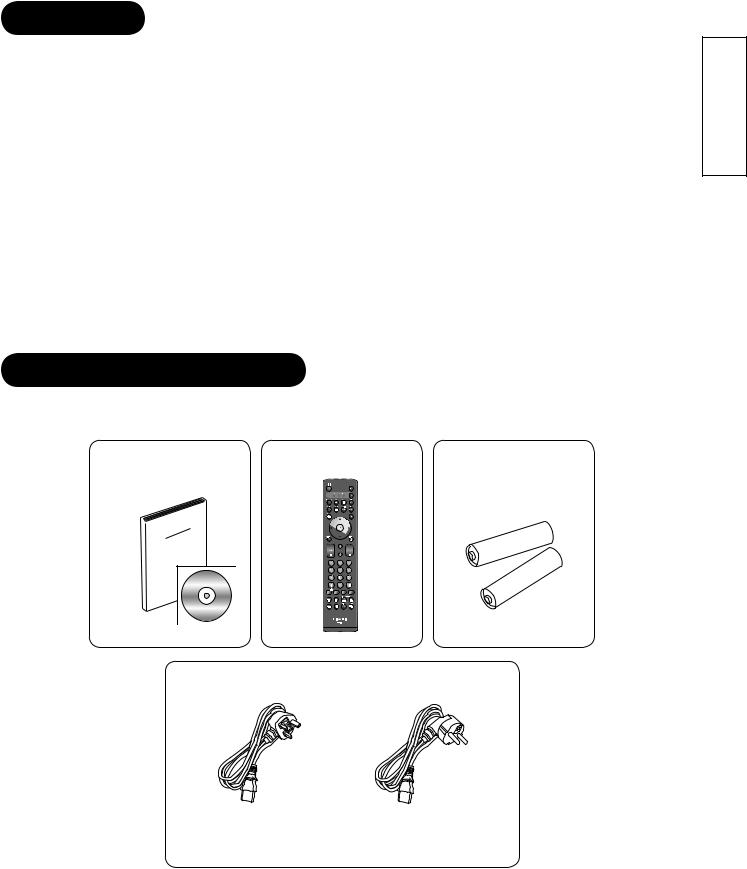
Check the supplied accessories before installation.
In case of missing or damaged, please contact the dealer immediately.
User Manual |
Remote Control |
AA size batteries |
|
|
X2 |
Power Cord
ENGLISH
UK only |
Except UK |
* The type of power plug provided is different depending on the model
*As for the installation of stand for 55PD9700U/C, please refer to the user manual provided in the carton box of stand.
9
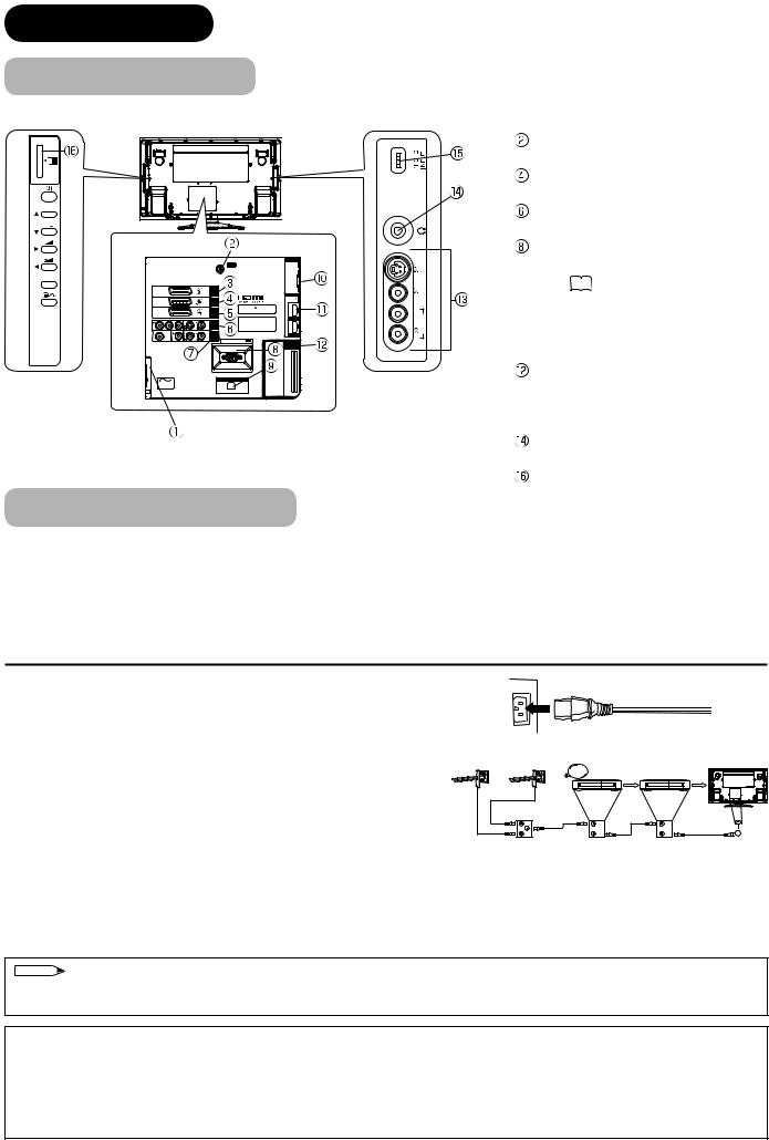
COMPONENT NAMES
Main Unit
Front Panel
1
2
6 3 5 4
1 Speaker
2 Panel
3 Main Power Switch (on the bottom surface)
4 Remote Control Receiver
5 Indicating Lamp
6 Desktop Stand
Rear Panel |
|
|
|
|
1 |
1 |
Handgrips (only for 42PD9700U/C) |
|
|
2 |
Side Input |
|
|
3 Terminal Board (External Device Connection) |
|
|
|
4 |
Power Cord Socket |
5 |
2 |
5 |
Control Panel (see below for details) |
|
|
||
|
|
Please refer to 14 ~ 19 for the detailed information |
|
|
|
for the connections. |
|
43
Control Panel (including Card Slot)
SD MEMORY CARD
PUSH-EJECT
P
P
 OK
OK
1
2
3
4
5
6
7
8
1 |
SD Memory Card Slot |
||||||
2 |
Sub Power button |
||||||
3 |
Channel UP/▲button |
||||||
4 |
Channel DOWN/▼button |
||||||
5 |
Volume UP |
|
|
|
|
/►button |
|
|
|
|
|
||||
6 |
Volume DOWN |
|
/◄button |
||||
|
|||||||
7 |
Input Select /OK button |
||||||
8 |
Menu / Return button |
||||||
PH35814
10
COMPONENT NAMES (Continued)
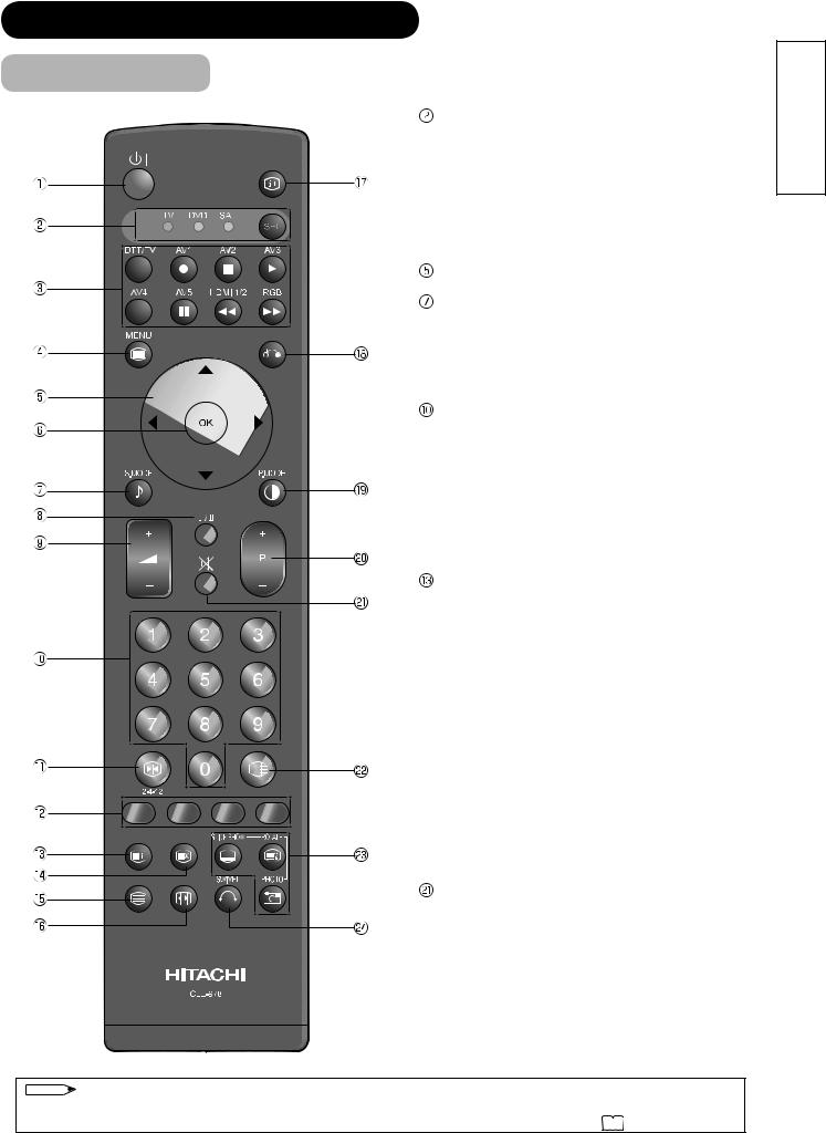
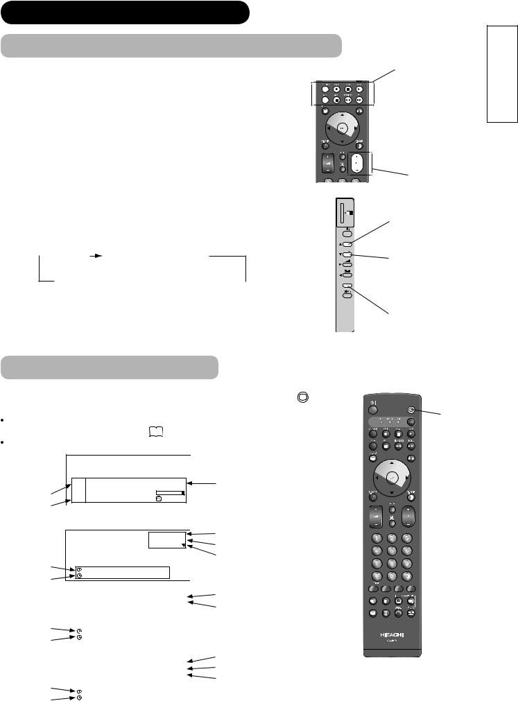
Remote Control
 Sub Power
Function Select (TV/DVD/SAT)
Press this button to select function mode indicating LED lamp.
Normally, select “TV”.
 Input Select/DVD Control/Photo Input Control
Press this button to change input mode.
In addition, you can use these buttons while operating the selected brand of DVD player or Photo Input function.
 Menu
Menu
Cursor
 OK
OK
Sound Mode
Sound mode can be changed each time pressed in the following sequence. Movie→Music→ Speech→Favourite
 CHI/II
This is exclusively for TV audio A2/NICAM mode.
 Volume Up/Down
Programme Select
Press these buttons to select a TV program directly.
 Freeze/Multi Mode [Hold]
Press this button to change the picture to freeze mode. Press it again to return to normal picture. In addition, during multi-picture mode, each time press this button, the picture is changed to 2, 4, and 12 multi mode. (Also, it holds the page in text mode.)
 [Colour (Red, Green, Yellow, Blue)]
[Index]
 Time [Cancel]
Pressing this button can indicate the time by OnScreen display when receiving a TV programme on the screen.
 TV/Text [TV Text]
This switches between the TV mode and the Teletext mode.
 Zoom [Text TV+Text]
Press this button to change picture size.
 Recall
Pressing this button shows the input signal status.
 Return
You can use this to return to the previous menu.
 Picture Mode
Picture mode can be changed each time pressed in the following sequence. Dynamic→Natural→ Cinema
 Channel Up/Down
Mute
 Multi Picture
Press this button to change the picture to multipicture mode. Press it again to return to normal picture.
 Photo Input (Photo/Rotate/Slide Show)
These buttons are to display and control the pictures from digital still camera or USB card reader.
 Swivel (with Desktop Stand)
This function is to rotate TV. Select the degree of rotation with cursor key.
NOTE
Some buttons are only for Teletext mode, and other buttons have different functions in Teletext mode from the use of TV mode. Those buttons are indicated by [ ]. Refer to "Analogue Teletext" on 39 .
ENGLISH
11
PREPARATION
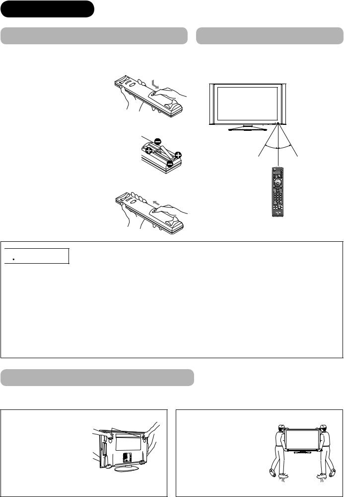
Remote Control Batteries Installation
This remote control operates on 2 “AA” batteries.
1. Open the battery compartment cover 
 Slide open the battery compartment cover on the backside of the remote control in the direction of an arrow.
2.Install the batteries
 Install 2 “AA” batteries (included) making
sure the polarities match the indication inside the compartment.
Handling the Remote Control
Use the remote control within about 5m from front of the unit’s remote-control sensor and within 30 degrees on both sides.
Within 30 |
Within 30 |
degrees |
degrees |
About 3m |
About 3m |
|
About 5m |
3. Close the battery compartment cover.
 To close the battery compartment cover, slide the cover in the direction of an arrow till it clicks shut.

 CAUTION
It could cause corrosion or battery leakage and may result in physical injury and/or property damage including fire.
 Never mix used and new batteries in the device.
 Replace all the batteries in a device at the same time.
 Remove the batteries if the remote control is not going to be used for an extended period of time.
To avoid possible failure, read the following instructions and handle the remote control properly.
 Do not drop or cause impact to the remote control.
 Do not spill water or any liquid on the remote control.
 Do not place the remote control on the wet object.
 Do not place the remote control under the direct sunlight or near sources of excessive heat.
Caution When Moving the Main Unit
As this product is heavy, whenever it is moved, two people are required to transport it safely.
42PD9700U/C |
|
Whenever the unit is moved, |
Handgrips |
it should be lifted forwards |
|
using the two handgrips at |
|
the back, and the unit should |
|
then be held at the base on |
|
both sides for stability. |
|
55PD9700U/C
When carrying this product, hold it by the top and bottom on both ends.
12
PREPARATION (continued)
Safety Precaution on Main Unit Installation
Read SAFETY PRECAUTIONS ( 4 to 7 ) carefully besides this page.
*The Desktop Stand has been used for the illustration in this manual.
When installing the main unit, be sure to use the specifi ed mount units in order to obtain maximum performance and maintain the safety.
We assume no responsibility or liability for personal injuries or property damages caused by use of other mount units or improper installation.
As for the installation instruction, please read each user manual of the mount units: for Desktop Setup, Wall Mounting, and Ceiling Mounting.
In case of using Wall or Ceiling Mounting unit, by contacting your local dealer, ask the specifi ed installation specialist to set up. Never attempt to install it by yourself. It could cause injuries or damages.
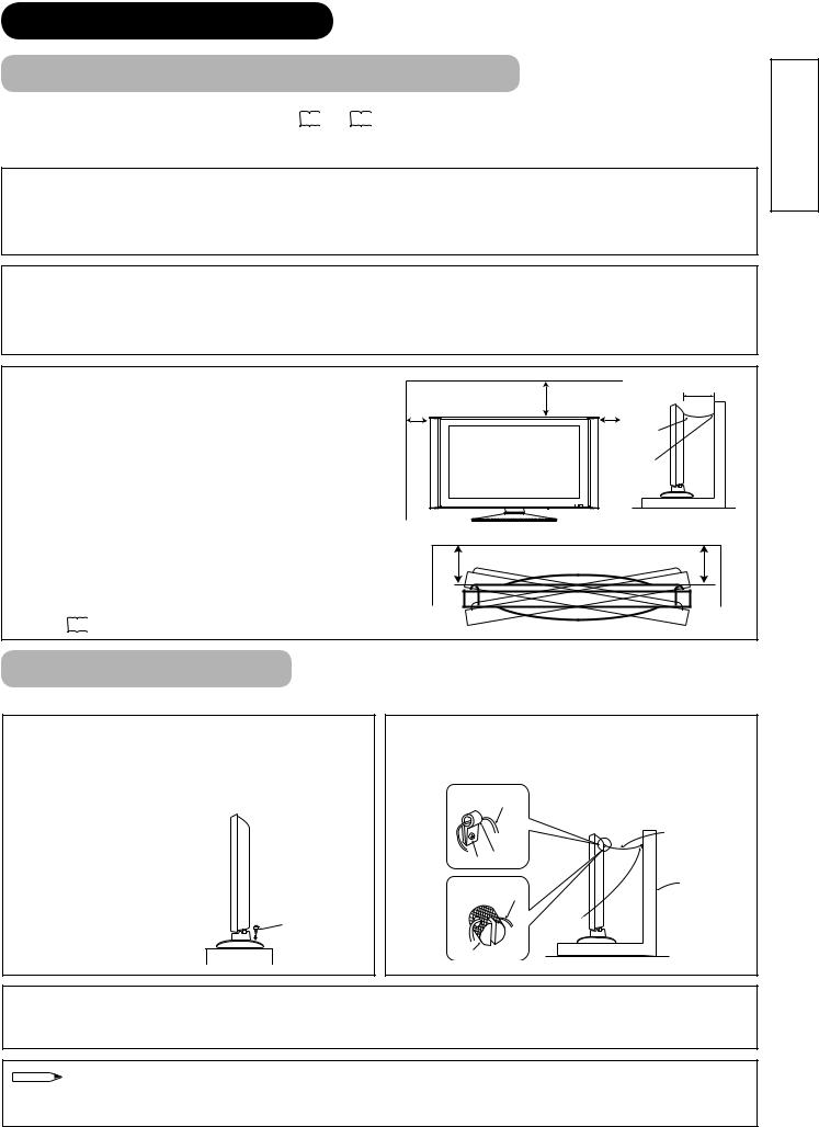
Please leave the adequate space around this unit in order to avoid increasing the internal temperature and keep safety while using swivel function.
Make sure not to block any ventilation holes.
Do not install the unit in the small space such as inside the rack, closet or the box.
Leave more than 10cm of clearance from each side of monitor and 30cm from the top of unit to wall.
Without Swivel function: Leave at least 10cm of clearance behind rear unit.
With Swivel function: Leave the adequate space to obtain the maximum performance of Swivel Function. (42PD9700U/C:31cm , 55PD9700U/C:42cm)
Refer to 51 for Swivel Function.
|
30cm |
10cm or more* |
|
10cm |
10cm |
||
or more |
|||
or more |
or more |
||
|
|||
|
|
Cord |
|
|
|
or |
|
|
|
chain |
|
|
|
Clamp |
Anti-Tumble Measures
Install in a stable place and implement safety measure against overturning.
Securing on desktop
Use two wood screws to secure the set fi rmly in position by fastening them to the screw holes at the rear of the stand as shown in the diagram. The wood screws are supplied with the stand.
Wood screw
Two places
Securing to a wall or pillar
Using a commercially available cord, chain, and clamp, secure the set to a wall or pillar.
42PD9700U/C: cord or chain
|
cord or chain |
hook |
|
screw |
|
55PD9700U/C: |
Wall or Pillar |
cord or chain |
|
|
clamp |
hook |
|
Securing to ceiling
Using a commercially available cord, chain, and clamp, secure the set to a ceiling.
NOTE
 For more information regarding the mounting of the unit, please contact your dealer.
  Loosen a cord or chain enough while operating power swivel to avoid physical injury.
ENGLISH
13
CONNECTION
Terminal Positions
SD MEMORY
CARD
PUSH-EJECT
P
P
 OK
OK
INPUT (AV1)
INPUT (AV2)
INPUT (AV3)
Y/VIDEO |
P |
P |
AUDIO |
|
|
INPUT |
C |
R |
(AV4) |
L |
|
|
SUB WOOFER |
AUDIO |
OUTPUT
L R
INPUT(RGB)
AUDIO
ANT
|
|
PC |
|
|
ANALOG RGB |
|
|
INPUT(HDMI) |
|
|
AUDIO |
WOW, SRS and |
symbol are |
|
trademarks of SRS Labs, Inc. |
|
|
Licensed by BBE Sound, Inc. under |
HDMI2 |
|
one or more of the following US |
|
|
patents : 5510752, 5736897. |
|
|
BBE and BBE symbol are registered trademarks of BBE Sound, Inc.
HDMI1
SERVICE USE ONLY
COMMON
INTERFACE
PH35814
POWER SWIVEL
A C
C.2C.1
Connecting Procedure
PH35826
|
|
S-VIDEO |
INPUT(AV5) |
L/MONO |
AUDIO VIDEO |
|
R |
|
Rear
 Power Cord Socket
Aerial Socket
 AV1
AV1
AV2
 AV3
AV3
AV4
 Monitor Out and Sub Woofer
Service use only
 Power Swivel Terminal (See 51 )
 PC Connection terminals (D-sub 15 pin and mini stereo for Audio)
 HDMI1, 2 and mini stereo for Audio Common Interface slot
Side
 AV5
AV5
Headphone terminal
 Photo Input terminal
SD Memory Card slot
This unit is ready for various kinds of connections. Make a connection in the following steps. Be sure to turn off the Main Power fi rst when connecting external equipments.
1.Connect Power Cord to the rear panel.
2.Connect Aerial Lead.
3.Connect your external equipments to the unit if any.
4.Connect the Power Plug to the Wall Socket.
1. Connecting Power Cord to the Rear Panel
Connect Power Cord to the monitor.
*Make sure not to connect the Power Plug to the Wall Socket until all connections are completed.
2. Connecting Aerial Lead.
Analogue |
Digital |
|
|
STB |
VCR |
There are two ways to connect Aerial Lead.
 When you do not have any other external equipment:
Connect the Aerial Lead directly into the Socket at rear panel.
 When you have one or more external devices to connect:
1.Use RF cable to connect between each equipment and Antenna.
IN |
IN |
OUT |
OUT |
[Example: Connecting Antenna
through STB and VCR]
2.Connect the Aerial Lead to an equipment‘In’Socket marked
3.Connect the RF cable from the equipment ‘Out’ to the other equipment ‘In.’
4.Then, connect from the equipment ‘Out’ to “ANT” on the plasma screen Socket on marked.
NOTE
 If analogue and digital broadcast signals are provided from the separated cables (antenna), please use a mixer and RF cable to connect antenna terminal in order to receive both signals.
Precautions when connecting the aerial
 Please use a coaxial cable which is free from interference to connect the aerial. Avoid using a parallel fl at feeder wire as interference may occur, causing reception to be unstable and stripe noise to appear on the screen.
 Avoid using indoor aerial as this may be affected by interference. Please use CATV net or outdoor aerial.
 If noise appears in the picture of VHF-Low band channel, please use a double-shielded cable (not provided) for RF LEADS to reduce the noise.
14
CONNECTION (continued)
Connecting Procedure (continued)
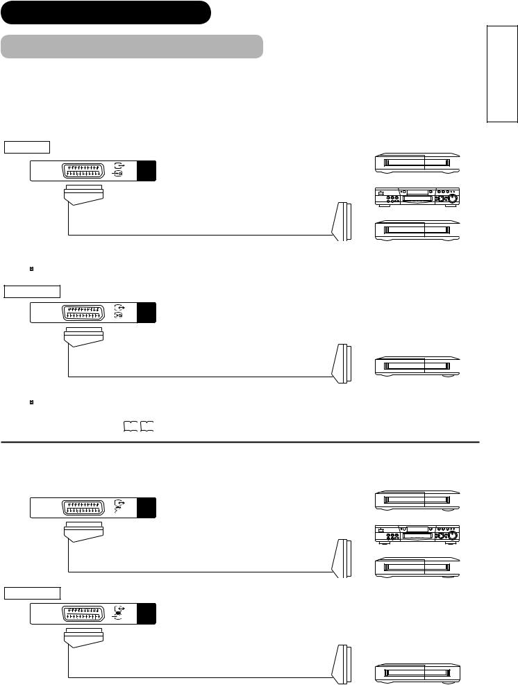
3. Connecting to External Equipment
 Terminals on Rear
AV1 can be connected to the equipment with Composite/S-Video/Audio input, and Composite/Audio output. The output signal can support not only Analogue but also Digital Terrestrial TV signals.
|
[Example] |
INPUT Composite/S-Video/Audio |
VCR |
INPUT |
|
(AV1) |
|
|
DVD player |
|
Set-Top Box |
IN |
OUT |
 If STB is connected to AV1 in France, it descrambles some of the Pay TV images by resending the signal again (In/Out).
OUTPUT Composite/Audio
INPUT (AV1)
[Example]
VCR
(Recording Device)
OUT |
IN |
 When you are watching either TV or DTT broadcasting from AV1, you can switch to the other by setting
"Scart Output" in Setup menu. For example, whilst you are watching TV, it is possible to record the DTT programme.Refer to 26 27 about "Scart Output" in Setup menu.
AV2 and 3 can be connected to the equipment with Composite/RGB/Audio input, and Composite/Audio output. [Example]
INPUT |
Composite/RGB/Audio |
VCR |
INPUT
(AV2)
DVD player
Set-Top Box
IN |
OUT |
OUTPUT Composite/Audio
INPUT (AV2)
[Example]
VCR
(Recording Device)
OUT |
IN |
ENGLISH
15
CONNECTION (continued)
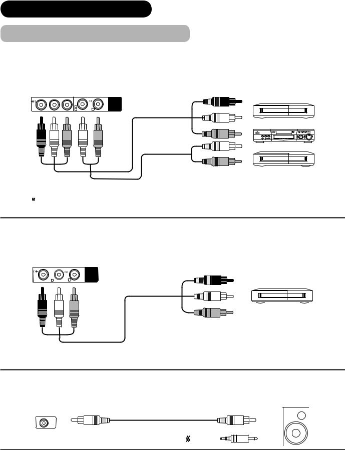
Connecting Procedure (continued)
AV4 can be connected to the equipment with either Component or Composite output. Depending on whether the Y/VIDEO input of your selected equipment is Y signal or Video signal, it automatically regards as Component or Composite. When using as Composite, do not insert the jacks into PB or PR.
|
IN |
OUT |
[Example] |
Y/VIDEO PB |
PR |
AUDIO |
VCR |
|
|
INPUT |
|
L(AV4)
CMONO R
DVD player
Set-Top Box
 If your external device has a Component terminal, COMPONENT connection is recommended for
higher quality picture.
Monitor Out can be used to display same image as main unit on another monitor.
When this output terminal is connected to an external monitor with a 75 Ohm terminal, the same image from composite(AV1~5), or RF signal can be displayed to the external monitor.
|
OUT |
IN |
[Example] |
VIDEO |
AUDIO |
|
|
L R
R
OUTPUT
VCR (Recording Device)
Sub Woofer terminal can bring the deep bass sound from the external speaker.
[Example]
OUT |
IN |
SUB WOOFER
or
16
CONNECTION (continued)
Connecting Procedure (continued)
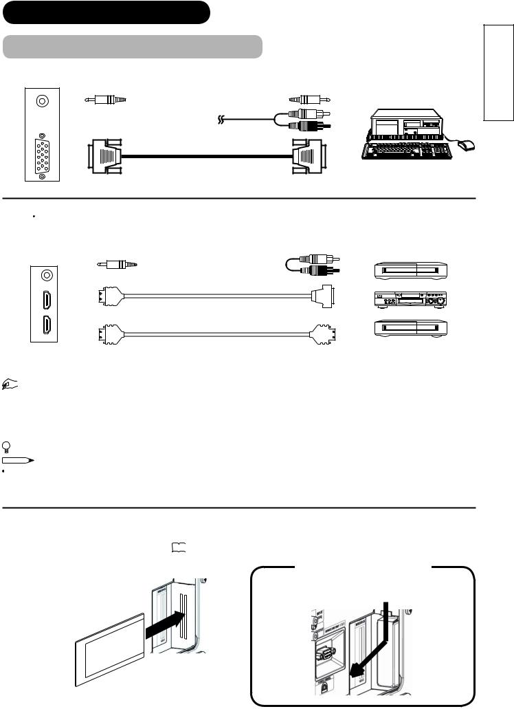
PC terminals (D-sub 15 pin + audio) is connected to PC, which allows Analogue RGB signal.
IN |
OUT |
|
[Example] |
(Mini Stereo plug) |
or |
|
HDMI 1 2 terminals can be connected to the devices with HDMI output, or if the external device has DVI output, this can be available with HDMI-DVI conversion cable. In case of using the HDMI-DVI, connect to audio terminal besides HDMI.
IN |
|
OUT |
[Example] |
|
|
|
VCR |
(Mini Stereo plug) |
|
|
|
|
|
|
DVD player |
(HDMI2) |
|
|
|
(HDMI) |
or |
(DVI) |
Set-Top Box |
(HDMI1) |
|
|
|
(HDMI) |
|
(HDMI) |
|


 Information
HDMI(High Defi nition Multimedia Interface) is next-generation multimedia I/O interface. Only one cable is used to transmit all video/audio/control signals, which creates easy connection.
Moreover, those digital signals can produce high quality data without any degradation. You are provided two HDMI terminals, one of the most remarkable features.
 If your external device has a HDMI terminal, HDMI connection is recommended for higher quality picture and sound.
NOTE
When both HDMI1 and HDMI2 terminals are connected to devices via HDMI-DVI conversion cable, HDMI2 has a priority over the audio terminal.
Common Interface Slot allows you to receive Pay TV service with detachable modules.
Before inserting the module, make sure to turn off the main power, and take off the cover of slot as shown and then insert the module all the way into the slot. Refer to 50 for the details.
Remove the slot cover
Push the top of slot cover to release the interlock and lift it the direction as shown.
Common Interface Module
ENGLISH
17
CONNECTION (continued)
Connecting Procedure (continued)
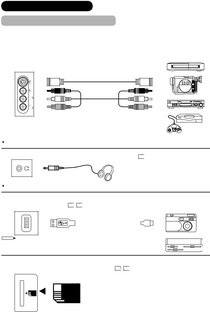
 Terminals on Side
Since the following terminals are located on the side, it is very convenient to connect an extra device on a temporary basis after completing the connections on the rear panel.
AV5 can be connected to the equipment with S-Video output and composite output.
IN |
OUT |
|
|
S-VIDEO |
INPUT(AV5) |
L/MONO |
AUDIO VIDEO |
|
R |
|
[Example]
VCR
Camcorder
DVD player
Home video game system
 If your external device has S-video terminal, S-VIDEO connection is recommended for higher quality picture.
Headphone The detail settings can be adjusted from Audio Menu on page 38 .
(Mini Stereo plug)
 The audio from the speaker will be muted when connecting the headphone to this terminal.
Photo Input terminal can be connected to digital still camera or USB card reader with USB cable. For details, refer to the Photo Input function shown on 61 ~ 66 . [Example]
PHOTO |
INPUT |
Digital Camera
IN |
|
OUT |
|
|
|
USB Card reader
NOTE
This photo input terminal does not support general USB devices such as USB memory. Please do not connect with those devices.
SD Memory Card slot can be used for the Photo Input function with the SD (or MMC) card memory containing pictures. For details, refer to the Photo Input function shown on 61 ~ 66 .
SD MEMORY
CARD |
SD Card / MMC |
|||||
|
|
|||||
|
|
|
|
|
|
|
|
|
|
|
|
|
|
|
|
|
|
|
|
|
PUSH-EJECT
18

CONNECTION (continued)
Connecting Procedure (continued)
4. Connecting the plug into the wall socket
Connect the Power Cord after completing all other connections. (The type of plug is different from this drawing for some countries.)
UK only
Except UK

 CAUTION
 Use only the Power Cord provided.
 Do not use a power supply voltage other than that indicated(AC100-240V, 50/60Hz). It may cause fire or electric shock.
 For the plasma television, a three-core power cord with a ground terminal is used for effi ciency protection. Always be sure to connect the Power Cord to a three-pronged grounded outlet and make sure that the cord is properly grounded. If you use a power source converter plug, use an outlet with a ground terminal and screw down the ground line.
 Ensure that both ends of power cord are easily accessible.
 If you have to change the power cord, please use the certifi ed power cord that meets your region’s safety standard.
 Information
 How to secure the cables.
After connecting all of the cables to the terminals, secure them with the band.
When you secure the cables, please be careful not to tighten too much.
INPUT (AV1)
INPUT (AV2)
INPUT (AV3)
Y/VIDEO |
PB |
PR |
AUDIO |
INPUT
L(AV4)
CMONO R
SUB WOOFER VIDEO |
AUDIO |
 OUTPUT
LR
ANT
WOW, SRS and symbol are trademarks of SRS Labs, Inc.
Licensed by BBE Sound, Inc. under one or more of the following US patents : 5510752, 5736897.
BBE and BBE symbol are registered trademarks of BBE Sound, Inc.
SERVICE USE ONLY
INPUT(RGB)
AUDIO
PC
ANALOG RGB
INPUT(HDMI)
AUDIO
HDMI2
HDMI1
COMMON INTERFACE
How to fasten the band:
 To tighten
 To loosen
Knob

Pull the band in the direction of the arrow.
Loosen the band by pushing the knob in the direction of the arrow.
POWER SWIVEL
A C
C.2C.1
ENGLISH
With long band
19
BASIC OPERATION
Power On/Off
Now, turn On the main power to the unit. Make sure that the Power Cord is plugged into the wall socket.
Main Power switch (on the bottom surface)
 To turn On the power of the unit:
1. |
Press the Main Power switch on the unit. |
|
|
The Indicating Lamp will illuminates in Red (Standby mode). |
|
2. |
Press Sub Power button either on the control panel or on the remote control. |
DTT/TV |
|
The colour of the Indicating Lamp turns into Green, and the image will Sub Power button |
|
|
display on the screen. |
|
 To turn Off the power of the unit:
SD MEMORY CARD
|
|
PUSH-EJECT |
1. |
Press Sub Power button either on the control panel or on the remote control. |
|
|
The image disappears from the screen and the Indicating Lamp turns into |
P |
|
|
|
|
Red (Standby mode). |
P |
|
|
|
2. |
Press Main Power switch to completely turn Off the power of the unit. |
Sub Power button |
OK |
|
The Indicating Lamp Status Check |
PH35814 |
|
|
|
|
|
Indicating Lamp |
Power Status |
Power Switch Status |
|
Status |
|
||
|
|
|
|
Off |
Off |
Main power → Off |
|
|
|
|
|
Red |
Standby mode |
Main power → On |
|
Sub Power button → Off |
|
||
|
|
|
|
|
|
Standby mode as above |
|
Blinks in Red |
Standby mode |
whilst upgrading DTT version and operating |
|
|
|
Timer Programming on digital channel. |
|
|
|
|
|
Green |
On |
Main power → On |
|
Sub power button → On |
|
||
|
|
|
|
Orange |
Power Save mode* |
Main power → On |
|
Sub Power button → On |
|
||
|
|
|
|
|
|
Power Save mode as above |
|
Blinks in Orange |
Power Save mode |
whilst upgrading DTT version and operating |
|
|
|
Timer Programming on digital channel. |
|
|
|
|
|
20
BASIC OPERATION (continued)
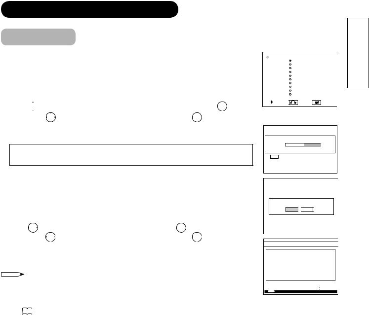
Easy Preset
When you turn ON the TV for the fi rst time, your TV automatically leads to the settings of “Language,” “Country” and “Auto Tuning.” (Also, refer to the attached Quick Guide.)
1.The fi rst screen appeared will ask you to choose the language of your Analogue TV’s display.
2.Using  button, select language you preferred from the list and press OK button.
3. Then, using |
button, select your residing country and press OK button. |
4.The auto tuning screen appears, and your TV will now search analogue channels through the frequencies storing them in order.
Depending on your residing country, it does not proceed to DTT auto tuning (5~8). DTT auto tuning process varies according to the model.
If you have 42/55PD9700U:
5.The dialogue box will appear to ask you if you wish to tune in the DTT channels and select “Yes” so that your TV will start searching the DTT channels.
If you have 42/55PD9700C:
5. |
The box appears to ask you to select language for DTT auto tuning. |
||
6. Using |
button, select language from the list and press OK button. |
||
7. |
Then, using |
button, select your residing country and press OK button. |
|
8.The dialogue box will appear to ask you if you wish to tune in the DTT channels and select “Yes” so that your TV will start searching the DTT channels.
NOTE |
MENU |
 If you want to change the setting after completing this easy preset, press
  button and set up individually.
- See 
 about the Analogue setting. - See 41 about the DTT setting.
 Language
English
Svenska
Norsk
Suomi
Dansk Česky Polski Magyar Slovenski Hrvatski
Select |
Return |
Exit |
This is an example of 42/55PD9700U.
Setup
Auto Tuning
Scanning Channel Number: 33
Cancel
OK Cancel
Do you want to start automatic search?
Yes 
 No
No
AUTOMATIC SEARCH
BBC ONE
BBC TWO
BBC THREE
BBC NEWS 24
BBCi
CBBC Channel
Searching UHF Channel: 61. Please wait. This will take a few minutes. 
0% |
100% |
|
MENU Cancel search
ENGLISH
21
BASIC OPERATION (continued)
Volume UP/DOWN
1.To increase the sound volume, press  button on the remote control, or Volume Up button on the control panel.
 The Volume Indicator value on the screen will shift right.
2.To decrease the sound volume, press  button on the
remote control or Volume Down button on the control panel.  The Volume Indicator value on the screen will shift left.
Mute
1.To mute the sound, press  button on the remote control.
 The sound of the unit is temporarily turned Off.
 The colour of the Volume Indicator will turn into magenta while muting the volume.
2.To turn the sound back, press  button again, or Volume Up button on either remote control or the control panel.
 The colour of the Volume Indicator will turn back to green.
NOTE
 You can decrease the volume by pressing
  button while the sound is muted.
Volume Up/Down
button
Mute button
SD MEMORY
CARD
PUSH-EJECT
Volume Up button
P
P
Volume Down button |
OK |
PH35814
Volume 15
The Volume Indicator
22
BASIC OPERATION (continued)
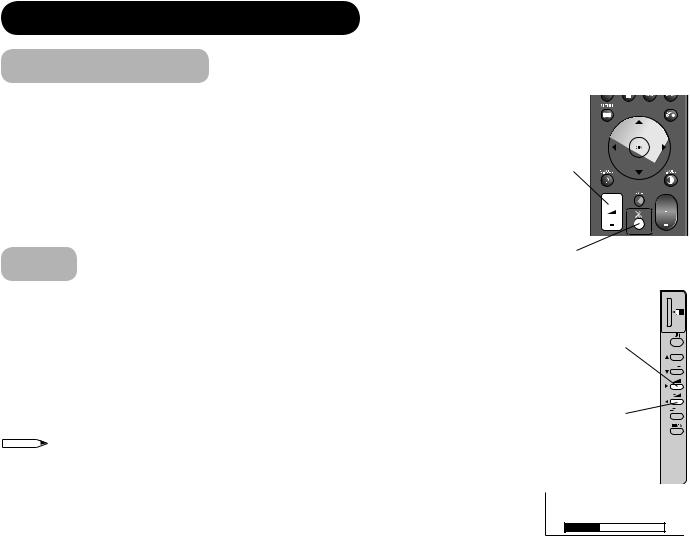
Input Switching to TV/AV1~5, HDMI, and RGB
By pressing Input Select button, you can switch the input.
 To watch actual broadcast, press Input Select button on the control panel, the numeric buttons or Channel Up/Down button on the remote control.
  To display the image outputting from the external equipments connected to each terminal (DTT / TV, AV1~5, HDMI 1 / 2, and RGB), select corresponding mode.
1. Press Input Select buttons on the remote control.
2.The Input modes can be also switched by using Input Select button on the control panel.
Each time this button is pressed, the screen displays corresponding mode by following order.
 DTT TV
 AV1
AV1 AV2
AV2  AV3
AV3
RGB HDMI 2
 HDMI 1
 AV5
AV5 AV4
AV4
3.To directly go back to TV mode, pressing channel Up/Down buttons on either remote control or the control panel.
Also, you can use the numeric buttons on the remote control.
SD MEMORY CARD
PUSH-EJECT
P
P
 OK
OK
PH35814
Input Select buttons
Channel
Up/Down button
Channel Up button
Channel Down button
Input Select button
Input Signal Screen Display
The input signal status can be displayed on the screen by pressing the  + button of the remote control.
The display in DTT mode will also appear as changing the channels and go out in |
Recall |
||||
button |
|||||
approximately 3 seconds. Refer to 44 about the information banner. |
|||||
|
|||||
The display in TV/Video/RGB mode will go out in approximately 6 seconds. |
|
||||
DTT |
|
|
|
|
|
Programme |
Now: ---- |
-- -- : -- -- - -- -- : -- -- |
Broadcasting time |
|
|
name |
Next: ---- |
-- -- : -- -- - -- -- : -- -- |
|
|
|
|
Signal Level: |
|
|
||
Channel |
1. ABCDE |
-- : -- |
|
|
|
|
|
|
|
||
name |
|
|
|
|
|
TV |
|
1 |
TV position |
|
|
ABCDE |
Name |
|
|
|
|
|
|
|
Sound mode |
Off-timer |
OFF |
-- -- Min. |
|
On-timer |
|
-- -- : -- -- |
|
|
|
|
VIDEO |
|
|
|
|
|
|
Input mode |
|
|
|
|
AV1 |
|
||
|
|
|
|
Composite |
|
Signal mode |
|
Off-timer |
|
|
|
|
|
|
|
|
|
|
|
|
|
|
|
|
OFF |
-- -- Min. |
|
|
|
||
On-timer |
|
|
-- -- : -- -- |
|
|
|
|
|
|
|
|
|
|
Input mode |
|
RGB |
|
|
|
|
|
|
|
|
|
|
|
|
|
||
|
|
|
|
|
RGB |
|
Input horizontal frequency |
|
|
|
|
H : 48.4kHz |
|
||
|
|
|
|
V : 60.1 Hz |
|
Input vertical frequency |
|
Off-timer |
|
|
|
|
|
|
|
|
|
|
|
||||
|
OFF |
-- -- Min. |
|
|
|
||
On-timer |
|
|
-- -- : -- -- |
|
|
|
|
|
|
|
|
|
|
|
|
ENGLISH
23
 Loading...