


Colour Plasma Display
Model PW2
USER'S MANUAL
42PD7500
42PD7500A
READ THE INSTRUCTIONS INSIDE CAREFULLY.
KEEP THIS USER'S MANUAL FOR FUTURE REFERENCE.
For future reference, record the serial number of your monitor.
SERIAL NO.
The serial number is located on the rear of the monitor.
USER'S MANUAL
Thank you very much for purchasing the HITACHI Plasma Display. Before using your monitor, please carefully read the "SAFETY INSTRUCTIONS" and this "USER'S MANUAL" so you will know how to operate the monitor properly. Keep this manual in a safe place. You will find it useful in the future.
Notes on lnstallation Work:
This product is marketed assuming that it is installed by qualified personnel with enough skill and competence. Always have an installation specialist or your dealer install and set up the product. HITACHI cannot assume liabilities for damage caused by mistake in installation or mounting, misuse, modification or a natural disaster.
Note for Dealers:
After installation, be sure to deliver this manual to the customer and explain to the customer how to handle the product.
1
Important
Please read this User's Instructions on Page 4
plasma monitor, which could shorten its lifespan, or cause injury to yourself. Should you encounter any difficulty in the set-up or operation of your monitor, firstly refer to the Troubleshooting guide at the rear of this manual.
In the unlikely event of a problem occurring with your plasma monitor, switch off at the mains sockets, pull out the plugs, and contact your dealer immediately.
CAUTION
Under no circumstances remove the rear cover of your plasma monitor.
Never guess or take any chances with electrical equipment of any kind - it is better to be safe than sorry!
Software Notice
It is prohibited for the end user of this product to copy, reverse engineer or reverse compile the software included therein, save to the extent permitted by law.
Plasma Monitor
After the plasma monitor has been on for any length of time, you will notice that the screen becomes warm. Please note that this is normal.
Sometimes the screen might have some tiny bright or dark spots. Please note that this is normal.
CAUTION
To prevent scratches or damages to the plasma screen, do not knock or rub the surface with sharp or hard objects. Clean the screen with a soft cloth moistened with warm water and dry with a soft cloth. A mild soap may be used if the screen is extremely dirty. Do not use harsh or abrasive cleaners!
CAUTION
Use a soft cloth to clean the cabinet and control panel of the monitor. When excessively soiled dilute a neutral detergent in water, wet and wring out the soft cloth and afterward wipe with a dry soft cloth.
Never use acid/alkaline detergent, alcoholic detergent, abrasive cleaner, powder soap, OA cleaner, car wax, glass cleaner, etc. especially because they would cause discoloration, scratches or cracks.
Information for users applicable in European Union countries
This symbol on the product or on its packaging means that your electrical and electronic equipment should be disposed at the end of life separately from your household wastes. There are separate collection systems for recycling in EU.
For more information, please contact the local authority or the dealer where you purchased the product.
FEATURES
Large-screen, high-definition plasma display panel
The 42-inch colour plasma display panel, with a resolution of 1024
(H) x 1024(V) pixels, creates a high-definition, large-screen (aspect ratio : 16:9) and low-profile flat display. Free from electromagnetic interferences from geomagnetic sources and ambient power lines, the panel produces high-quality display images free from colour misconvergence and display distortion.
High Performance Digital Processor
A wide range of input signals can be handled, including composite, component, and HDMI.
High Definition Digital Processor creates the fine-textured image with dynamic contrast.
In addition, it corresponds to a broad array of personal computer signals, from 640 x 400, and 640 x 480 VGA to 1600 x 1200 UXGA. (Analogue Input)
Easy-to-use remote control and on screen display system
The remote control included eases the work of setting display controls. Further, the on-screen display system, displays the status of signal reception and display control settings in an easy-to-view fashion.
Connecting to an Audio Visual Device
• Two Scart terminals*1, composite/S terminal*2, a component terminal*3, and a HDMI terminal have been added. A composite video output terminal is also provided as a monitoring output.
*1 |
AV1 scart applies to composite/ S-video |
|
|
|
AV2 applies to composite/ RGB |
*2 |
A composite/S terminal = Side Input |
*3 |
With AV3 input, if a composite terminal and a component |
|
terminal are used at the same time, the component terminal |
|
would govern. |
•A wide range of devices can be also connected besides personal computers.
Power Swivel Feature
It allows turning the plasma display left or right within ± 30 degree using the remote control.
Digital Terrestrial Television Broadcasting
Converting into digital signal enables to provide more channels and various useful features, such as Electric Programme Guide, Digital Teletext, and so on. Further, digital signal can create high quality picture.
This logo indicates that the product is compliant with European Digital Broadcasting.
DVB is a registered trademark of the DVB Project.
This logo indicates that the product is set up to view digital terrestrial TV.
FREEVIEW and the FREEVIEW logo are trade marks of DVT Services Ltd and are used under license. FREEVIEW Logo © DTV Services Ltd 2002.
This logo indicates that the product will work after implementation of full digital switchover.
The Digital logo is a Certification Mark.
2

CONTENTS |
|
FEATURES .................................................... |
2 |
SAFETY INSTRUCTIONS .............................. |
4 |
IMAGE RETENTION OF PLASMA DISPLAY |
..8 |
COMPONENT NAMES .................................. |
9 |
Main Unit ............................................................................ |
9 |
Remote control .................................................................. |
10 |
Loading Batteries ............................................................ |
10 |
Handling the Remote Control.......................................... |
10 |
INSTALLATION INSTRUCTIONS ................ |
12 |
Installation.......................................................................... |
12 |
Anti-tumble measures........................................................ |
12 |
Connecting to an Audio Visual Device.............................. |
13 |
Connecting to a PC .......................................................... |
15 |
Mounting the Speaker Unit................................................ |
16 |
Mounting the Side Input .................................................... |
18 |
Power Cord Connection .................................................... |
19 |
BASIC OPERATION .................................... |
20 |
Turning Power On and Off ................................................ |
20 |
Input Switching .................................................................. |
21 |
Size Switching .................................................................. |
21 |
Volume Adjustment............................................................ |
23 |
Audio Mute ........................................................................ |
23 |
Power Swivel .................................................................... |
24 |
Input Signal Screen Display .............................................. |
25 |
Displaying MULTI PICTURE .............................................. |
26 |
Picture Freezing ................................................................ |
28 |
DIGITAL TERRESTRIAL TELEVISION (DTT) |
|
OPERATION ................................................ |
29 |
Using the Menu Screen (On-screen display system) ...... |
29 |
Installing the Channels ...................................................... |
30 |
Changing the Channels .................................................... |
31 |
Editing the Channels ........................................................ |
32 |
Utilizing the Information Tool ............................................ |
32 |
Setting Timer and Programme Reminder.......................... |
35 |
Configuring the Setting...................................................... |
36 |
Using Common Interface .................................................. |
37 |
TV Setup Menu .................................................................. |
37 |
TV SETUP OPERATION .............................. |
38 |
Using the Menu Screen (On-screen display system) ...... |
38 |
SETUP MENU (TV mode) .................................................. |
39 |
SETUP MENU (Video mode) ............................................ |
41 |
SETUP MENU (RGB mode: RGB1 (DVI-PC), |
|
RGB2 (RGB)) .................................................................. |
42 |
FUNCTION MENU ............................................................ |
44 |
PICTURE MENU (TV/Video mode) .................................... |
45 |
PICTURE MENU (RGB mode) .......................................... |
48 |
AUDIO MENU .................................................................... |
49 |
TIMER MENU .................................................................... |
50 |
ANALOGUE TELETEXT .................................................... |
50 |
OTHER FUNCTIONS .................................. |
51 |
Automatic Store ................................................................ |
51 |
Audio Switching ................................................................ |
52 |
Power Save Mode ............................................................ |
53 |
DVD Player/STB Selection ................................................ |
53 |
Signal Check (RGB mode) ................................................ |
54 |
TROUBLESHOOTING.................................. |
55 |
Symptoms That Seemingly Appear to be Failures............ |
55 |
Actions to Correct Abnormal Displays .............................. |
57 |
PRODUCT SPECIFICATIONS ...................... |
58 |
Signal Input ...................................................................... |
59 |
Recommended Signal List ................................................ |
60 |
Notes about This Manual
•The information in this manual is subject to change without notice.
•Whilst meticulous care has been taken in the preparation of this manual, you are requested to notify your dealer or us should you have any comments, views or questions about our product.
•Fully understand the prerequisites to using the product, such as hardware and software specifications and constraints, in using the product. We are not held liable for damages caused by improper handling of the product.
•Reproduction of this manual in whole or in part without our prior written permission is prohibited.
•The product names mentioned in this manual may be trademarks or registered trademarks of their respective owners.
3
SAFETY INSTRUCTIONS
This Plasma monitor has been designed and manufactured to meet international safety standards, but like any electrical equipment, care must be taken if you are to obtain the best results and safety is to be assured.
Before using this product, please read and understand the Safety Instructions thoroughly to ensure correct usage, and follow all the instructions.
About the Symbols
Various symbols are used in this manual, the user’s manual and on the product itself to ensure correct usage, to prevent danger to the user and others, and to prevent property damage. The meanings of these symbols are described below. It is important that you read these descriptions thoroughly and fully understand the contents.

 WARNING

 CAUTION
Typical Symbols
This symbol indicates information that, if ignored, could possibly result in personal injury or even death due to incorrect handling.
This symbol indicates information that, if ignored, could result possibly in personal injury or physical damage due to incorrect handling.
This symbol indicates an additional warning (including cautions). An illustration is provided to clarify the contents.
This symbol indicates a prohibited action. The contents will be clearly indicated in an illustration or nearby (the symbol to the left indicates that disassembly is prohibited).
This symbol indicates a compulsory action. The contents will be clearly indicated in an illustration or nearby (the symbol to the left indicates that the power plug should be disconnected from the power outlet).

 WARNING
Never use the monitor if a problem should occur.
Abnormal operations such as smoke, strange odor, no image, no sound, excessive sound, damaged casing, elements, cables, penetration of liquids or foreign matter, etc. can cause a fire or electrical shock.
In such case, immediately turn off the power switch and then disconnect the power plug from the power outlet. After making sure that the smoke or odor has stopped, contact your dealer. Never attempt to make repairs yourself because this could be dangerous.
Disconnect the plug from the power outlet.
Do not insert liquids or foreign objects.
Penetration of liquids or foreign objects could result in fire or electrical shock. Use special caution in households where children are present.
If liquids or foreign objects should enter the monitor, immediately turn off the power switch, disconnect the power plug from the power outlet and contact your dealer.
•Do not place the monitor in a bathroom.
•Do not expose the monitor to rain or moisture.
•Do not place flower vases, pots, cups, cosmetics, liquids such as water, etc on or around the monitor.
•Do not place metals, combustibles, etc on or around the monitor.
Never disassemble or modify the monitor.
The monitor contains high voltage components. Modification could result in fire or electrical shock.
• Never remove any fixed cover.
Do not disassemble.
Do not give the monitor any shock or impact.
If the monitor should be shocked and/or broken, it could result in an injury, and continued use could result in fire or electrical shock. If the glass panel is broken or damaged, immediately turn off the power switch, disconnect the power plug from the power outlet and contact your dealer.
Do not place the monitor on an unstable surface.
If the monitor should be dropped and/or broken, it could result in an injury, and continued use could result in fire or electrical shock.
• Do not place the monitor on an unstable, slant or vibrant surface such as a wobbly or inclined stand.
Do not obstruct the ventilation of the monitor.
If the ventilation is obstructed during the operation of the monitor or just after switching off the power, it could result in damage and shorten the lifespan of your monitor due to overheating. Make sure there is ample ventilation.
•Keep a space of 100mm (10cm) or more between the sides, rear and top of the monitor and other objects such as walls.
•Do not place anything around ventilation openings of the monitor.
•Never block ventilation openings.
•Do not put the plasma screen side up.
•Do not cover the monitor with a tablecloth, etc.
•Do not place the monitor on a carpet or bedding, or near a curtain.
Use only the correct power outlet.
Incorrect power supply could result in fire or electrical shock. Use only the correct power outlet depending on the indication on the monitor and the safety standard.
• The enclosed power cord must be used depending on the power outlet to be used.
4
SAFETY INSTRUCTIONS (continued)
About the Symbols (continued)
a soft and dry cloth to clean the power plug. or contact failure.
. If you wish to extend the lead,
replace with new one of the same value,
.
at the power outlet using the enclosed of the obsolete outlet.
Surely connect the ground wire.
Be careful in handling the power cord and external connection cables.
If you keep using a damaged the power cord or cables, it can cause a fire or electrical shock. Do not apply too much heat, pressure or tension to the power cord and cables.
If the power cord or cables are damaged (exposed or broken core wires, etc.), contact your dealer.
•Do not place the monitor or heavy objects on the power cord and cables. Also, do not place a spread, cover, etc, over them because this could result in the inadvertent placing of heavy objects on the concealed power cord or cables.
•Do not pull the power cord and cables. When connecting and disconnecting the power cord or cables, do it with your hand
holding the plug or connector.
•Do not place the cord near the heater.
•Do not touch the power plug just after disconnecting it from the power outlet to prevent electric shock.
•Do not touch the power plug when lightening is close to you.
•Avoid coiling the power cord and bending it sharply.
•Protect the power cord from being walked on, pinched particularly at plugs, conveniences receptacles, and the point where they exit from the apparatus.
•Do not modify the power cord.
Be careful in handling the battery of the remote control.
Incorrect handling of the battery could result in fire or personal injury. The battery may explode if not handled properly.
•Keep the battery away from children and pets. If swallowed consult a physician immediately for emergency treatment.
•Do not allow the battery to be exposed to fire or water.
•Avoid fire or high-temperature environment.
•Do not hold the battery with metallic tweezers.
•Keep the battery in a dark, cool and dry place.
•Do not short circuit the battery.
•Do not recharge, disassemble or solder the battery.
•Do not physically impact the battery.
•Use only the battery specified in the manual of this monitor.
•Make sure the plus and minus terminals are correctly aligned when loading the battery.
•If you observe a leakage of the battery, wipe out the liquid and then replace the battery. If the liquid adheres your body or clothes, rinse well with water.
•Obey the local laws on disposing the battery.
IMPORTANT FOR UNITED KINGDOM
WORDING FOR CLASS I EQUIPMENT INSTRUCTION BOOKS AND LABELS
The mains lead on this equipment is supplied with a molded plug incorporating a fuse, the value of which is indicated on the pin face of the plug. Should the fuse need to be replaced, an ASTA or BSI approved BS 1362 fuse must be used of the same rating. If the fuse cover is detachable never use the plug with the cover omitted. If a replacement fuse cover is required, ensure it is of the same colour as that visible on the pin face of the plug. Fuse covers are available from your dealer.
DO NOT cut off the mains plug from this equipment. If the plug fitted is not suitable for the power points in your home or the cable is too short to reach a power point, then obtain an appropriate safety approved extension lead or consult your dealer. Should it be necessary to change the mains plugs, this must be carried out by a competent person, preferably a qualified electrician. If there is no alternative to cutting off the mains plug, ensure that you dispose of it immediately, having first removed the fuse, to avoid a possible shock hazard by inadvertent connection to the mains supply.
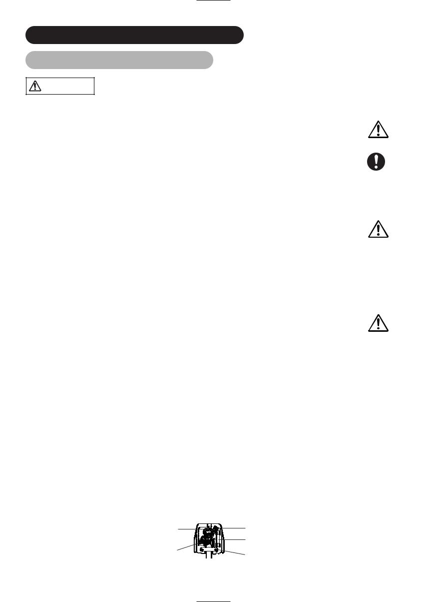
WARNING: THIS EQUIPMENT MUST BE EARTHED
IMPORTANT
The wires in the mains lead are coloured in accordance with the following code : Green and Yellow = Earth, Blue = Neutral, Brown = Live.
As these colours may not correspond with the coloured markings identifying the terminals in your plug, proceed as follows:
The wire which is coloured GREEN and YELLOW must be connected to the terminal in the plug which is marked with the letter E or by the earth symbol  or coloured GREEN or GREEN and YELLOW.
The wire coloured BLUE must be connected to the terminal marked with the letter N or coloured BLUE or BLACK. The wire coloured BROWN must be connected to the terminal marked with the letter L or coloured BROWN or RED.
Green & Yellow |
Brown to Live |
to Earth |
Fuse |
|
|
Blue to Neutral |
Cord Clamp |
|
5
SAFETY INSTRUCTIONS (continued)
About the Symbols (continued)
all external connections.
injury or damage. Use special caution in
could result in fire or electrical shock. or humidity.
in transformation, melting or fire. a hot object such as heater, etc.
periods of time. shock.
Be careful in operating power swivel.
Placing hands or faces near the monitor whilst operating the swivel function could cause a physical injury or damage. Use special caution in households where children are present.
PRECAUTIONS
Installation environment
Disconnect the plug from the power outlet.
Do not obstruct a ventilation hole.
Do not put the monitor on carpet or blanket, or near a curtain which has a possibility of obstructing a ventilation hole of the monitor. Do not put the monitor in the following places.
•Hot places such as near heater, place exposed to the direct rays of the sun.
•A place where the temperature is widely changing.
•Places with soot, dust or high humidity.
•Poor air ventilation place.
•Place near fire.
•A wet place such as bathroom, or shower room.
•Place where you can trip over it.
•Always vibrating or strongly vibrating places.
•Distorted or unstable places.
How to view the monitor
If you use the monitor in too dark a room, your eyes may become tired.
Please use it in a reasonably bright room.
Avoid direct rays of the sun to the screen in order to prevent eye fatigue.
Your eyes will get fatigued after viewing the monitor for long period of time.
Relax your eyes by viewing away from the monitor from time to time.
Please watch the monitor in downward direction.
Note on image retention
The plasma monitor illuminates phosphor to display images. The phosphor has a finite illumination life. After extended periods of illumination, the brightness of the phosphor will be degraded to such extent that stationary images would burn-in that part of the screen as greyed-out images. Tips to prevent such image retention are:
•Do not display images having sharp brightness differences or high-contrast images, such as monochrome characters and graphic patterns, for long.
•Do not leave stationary images appearing for long, but try to refresh them at appropriate intervals of time, or try to move them using screen saver function.
•Turn down the contrast and brightness controls.
How to clean the plasma screen panel of the monitor
Before cleaning the monitor, turn off the monitor and disconnect the power plug from the power outlet.
To prevent scratching or damaging the plasma screen face, do not knock or rub the surface with sharp or hard objects. Clean the screen with a soft cloth moistened with warm water and dry with a soft cloth. If it is not enough, then use a cloth with mild detergent. Do not use harsh or abrasive cleaners.
How to clean the cabinet of the monitor
Use a soft cloth to clean the cabinet and control panel of the monitor. When excessively soiled dilute a neutral detergent in water, wet and wring out the soft cloth and afterward wipe with a dry soft cloth.
Never use acid/alkaline detergent, alcoholic detergent, abrasive cleaner, powder soap, OA cleaner, car wax, glass cleaner, etc. especially because they would cause discoloration, scratches or cracks.
6

SAFETY INSTRUCTIONS (continued)
About the Symbols (continued)
prevent a problem to Radio receivers.
other than the monitor. above.
between the pieces of equipment), are withdraw the power plug before making or changing
such as Radio etc.
is transported.
to the monitor.
could invalidate the remote control.
.
neighborhood environment.
safety, always fit the manufacturers approved stand
or sold with the apparatus. When a cart is used, use
stability. Do not apply excessive pulling force to the damage and/or personal injury.
.
your equipment.
that it is designed for unattended operation or has a how to do this. Make special arrangements for infirm or
region.
to be safe than sorry!
7
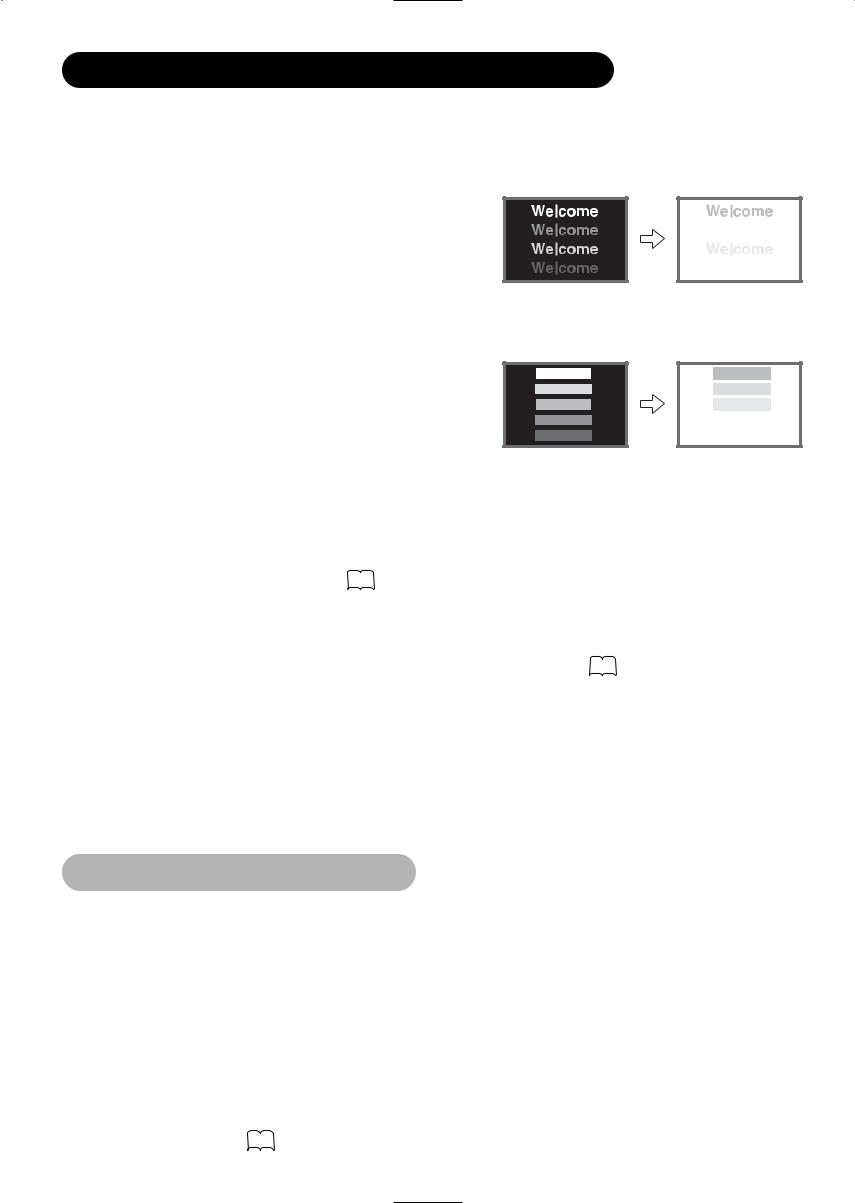
IMAGE RETENTION OF PLASMA DISPLAY
There are different characteristics that result in panel image retention depending on how the plasma display is used. Situations and effective usage methods related to ghosting are provided below.
Image retention characteristics of a plasma display
The image retention phenomenon of a plasma panel occurs due to partial phosphor degradation arising from partial character and figure display.
For example, when the character image as shown in Fig. A at the right is continuously displayed for a long period of time, the only part of the phosphor (Red, Green, Blue) that will degrade will be the colour of the applicable character display portion. Consequently, when a white image is displayed on the entire screen as shown in Fig. a, the character marks displayed up to that time will become a colour difference visible to the eye, but the phosphor will never burn.
[Fig. A] |
[Fig. a] |
■ The degree of image retention is proportional to the brightness of the characters and figures displayed as well as the display time.
• The tendency of the phosphor is to degrade more the brighter the characters and figures are displayed. When images of figures with different levels of brightness, as shown in Fig. B, are continuously displayed for a long period of time, it becomes easier for image marks at locations when the brighter figures are displayed to be noticeable.
[Fig. B] |
[Fig. b] |
*The image retention images in this document are exaggerated for the purpose of explanation. The actual manner in which the image retention is seen differs depending on the operation time and brightness.
Methods to Reduce the Occurrence of Image Retention
• Lower the Contrast and Brightness settings of the plasma display as much as possible.
A function is provided in the display that controls the brightness of the screen to reduce degradation of the panel. Using this function makes it possible to reduce image retention.
(Refer to Panel Life (Extend 1.or Extend 2) shown on
• Set the plasma monitor to an “Screen Wipe” or “Luminance Manager” display.
The occurrence of image retention when displaying images of identical patterns, such as static images, for long periods of time can be reduced by displaying a completely white screen for about 1 ~ 2 hours after terminating the display. Using Luminance Manager function works to reduce image retention when displaying images on the four corners, such as TV station logos and clock display.
(Settings can be made using Screen Wipe and Luminance Manager from Function MENU shown on 44 .)
uniform for moving images, the occurrence of partial image moving images such as a DVD.
in a two screen display state for a long period of time.
time in which the left and right or top and bottom of the image are cut of time at the same portion of the screen. Image retention in these
Notes
About screen defects
•High precision technology is used in the making of plasma panels but there may be dark spots (points that do not illuminate) and bright spots (points that are too bright) in some cases. These do not indicate a malfunction.
About residual images
•In some cases, residual images may remain after the short-term display of still images and another image is displayed, but these will disappear and return to normalcy. This is not a malfunction.
About the panel screen
•Plasma displays display images by means of electrical discharges inside the panel. Because of this, the temperature of the panel surface may rise in some cases. Also, plasma displays are made of finely processed glass. A reinforced glass filter is installed over the panel surface but avoid strong impact because there is still danger of glass breakage.
About the power swivel
•Do not put hands or faces close to the monitor whilst operating the swivel function. It could cause a physical injury. Use special caution in households where children are present.
(Refer to Power Swivel shown on 24 .)
8

COMPONENT NAMES
Main Unit
Front
Panel |
Cabinet |
|
(front frame) |
||
|
Control panel
• Adjustment buttons are located on the bottom.
• The back cover is provided with indications to distinguish the adjustment buttons.
Remote-control
10
receiver
Indicating lamp 20
• The main power switch is located at the back, on the
|
|
|
|
MENU button 38 |
lower surface. |
|
|
|
|
Main power switch 20 |
|
|
|
|
|
|
|
|
|
|
|
INPUT SELECT button 21 |
|
VOLUME |
|
|
(OK button) |
|
|
UP/DOWN |
|
||||
CHANNEL |
|
||||
buttons |
23 |
|
|||
UP/DOWN buttons |
|
||||
( |
button) |
|
|||
( |
button) 21 |
|
|||
|
|
|
|
||
SUB-POWER button 20
• ( ) indicates the function whilst the MENU is displayed on the screen.
Caution when moving the main unit
•As this product is heavy, whenever it is moved, two people are required to transport it safely.
•Whenever the unit is moved it should be lifted forwards using the two handgrips at the back, and the unit should then be held at the base on both sides for stability.
Handgrips
|
Rear |
Handgrip |
Handgrip |
External |
External |
speaker |
speaker |
terminals |
terminals |
15 |
15 |
External device connection terminals
RGB input terminals
9
COMPONENT NAMES (continued)
Remote control
POWER button
INPUT SELECT buttons
MENU button
OK button
SOUND MODE button
VOLUME UP/DOWN button
PROGRAMME SELECT buttons
RECALL button
FUNCTION SELECT button
DVD CONTROL buttons
RETURN button
CURSOR button PICTURE MODE button CH I/CH II button
CHANNEL UP/DOWN button MUTE button
FREEZE/MULTI MODE |
MULTI PICTURE button |
button
TV/TEXT button
SWIVEL button
Loading Batteries
1.Open the battery cover.
•Slide back and remove the battery cover in the direction of the arrow.
2.Load batteries.
•Load two Size AA batteries included observing the correct polarities.
3.Close the battery cover.
•Replace the battery cover in the direction of the arrow and snap it back into place.
Handling the Remote Control
Use the remote control within about 5 m from front of the unit’s remote-control sensor and within 30 degrees on both sides.
Within 30 Within 30 degrees degrees
About 3m |
About 3m |
About 5m

 CAUTION
•Do not use new and old batteries together. The batteries could explode or leak, resulting in fires, physical injury, or stains.
•When loading batteries, observe their correct polarities as marked on the product. If loaded in the wrong direction, the batteries could explode or leak, resulting in fires, physical injury, or stains.
ATTENTION
•Do not drop or impact the remote control.
•Do not splash the remote control with water or put it on a wet object to avoid possible failures.
•Before leaving the remote control out of use for an extended period of time, remove the batteries from it.
•If the remote control begins to lack responsiveness, replace the batteries.
•Strong light such as direct sunlight impinging on the photoreceptor of the remote control can cause operational failure. Position this unit to avoid direct contact with such light.
10

COMPONENT NAMES (continued)
function *1
RECALL (TV/Video/RGB)
Press this button to display input signal.
DVD CONTROL
You can use these buttons to operate the selected brand of DVD player.
RETURN
Press this button to return to the previous screen or normal picture.
PICTURE MODE
You may recall the picture mode by pressing this button. Each time pressed, picture mode is changed in following sequence.
 Dynamic
  Natural
  Cinema
MUTE
Press this button to turn off the set sound. When press again or the volume up button, the audio will be restored.
MULTI PICTURE
Press this button to change the screen to multi-pictures. Press it again to return to normal picture.
SWIVEL
Press this button to rotate TV. Use cursor key ( ) to select the degree of rotation.
These buttons are not available in this model.
DVD Player, DVD Recorder, and Set Top Box as well as this set. modes.
below the function selected.
53
or blinking).
 button to change modes when the LED is lit.
. You can set up the maker of DVD or STB whilst the LED is still
53 54 .
11
INSTALLATION INSTRUCTIONS
Installation

 WARNING
Use one of the special mount units to install this product. A mount of insufficient strength or inadequate design can cause overturning or dropping and result in fire, electrical shock or injury. Please note that our company assumes absolutely no responsibility for personal injuries or property damage caused by use of other mount units or improper installation.
10cm (4 inches as walls, etc.,
Cord or chain
Wall or Pillar
Clamp
 10cm or more*
Anti-tumble measures

 CAUTION
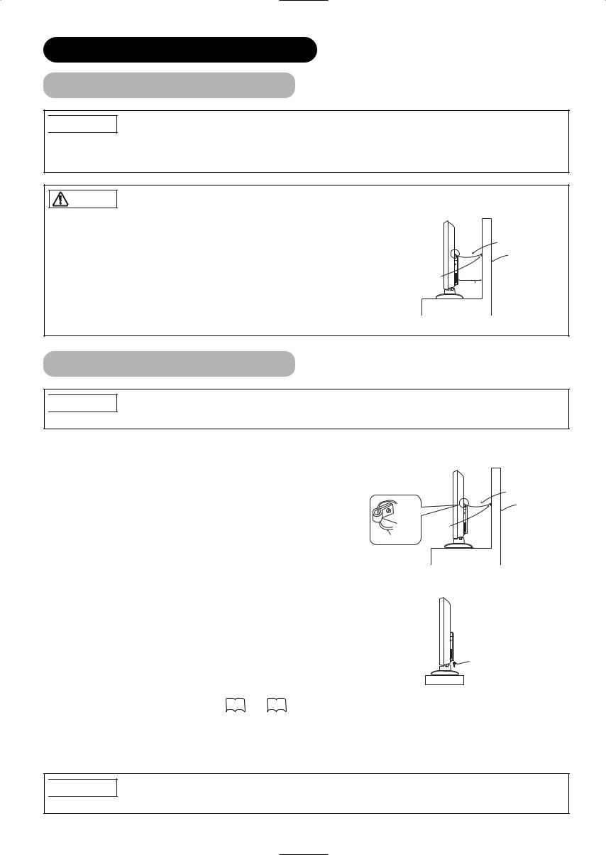
Have this unit mounted in a stable place. Take measures to prevent it from tumbling down to avoid possible physical injury.
Securing to a wall or pillar
Using a commercially available cord, chain and clamp, secure the set to a firm wall or pillar.
Cord or chain
Wall or Pillar
Hook Clamp
Cord or chain
Securing desktop
1)Using wood screws (two), fasten the set to the clamping screw holes on the rear of the stand as shown.
2)Using commercially available wood screws, secure the set firmly in position.
Wood screw
 Two places
Read SAFETY INSTRUCTIONS ( 4 to 7 ) carefully to ensure maximum safety before proceeding to these steps:
•Choose an appropriate site and install the product on a level table where the stand is secure.
•Install the monitor to have ready access to a power socket available.
•Make sure that the power switch of this device is turned off.

 CAUTION
Loosen a cord or chain enough whilst operating power swivel to avoid possible physical injury.
12
INSTALLATION INSTRUCTIONS (continued)
terminal on the rear panel of this
(rear panel) |
Speaker (L) |
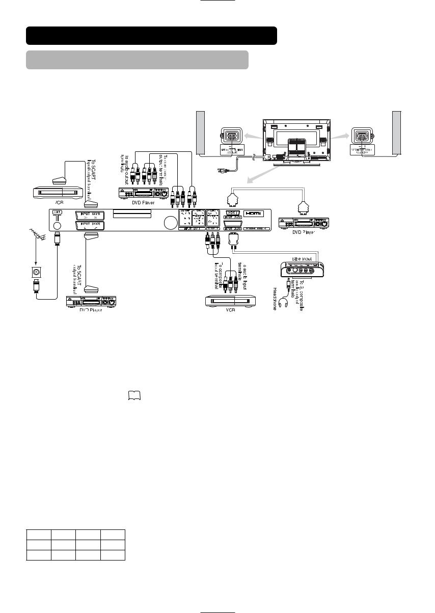
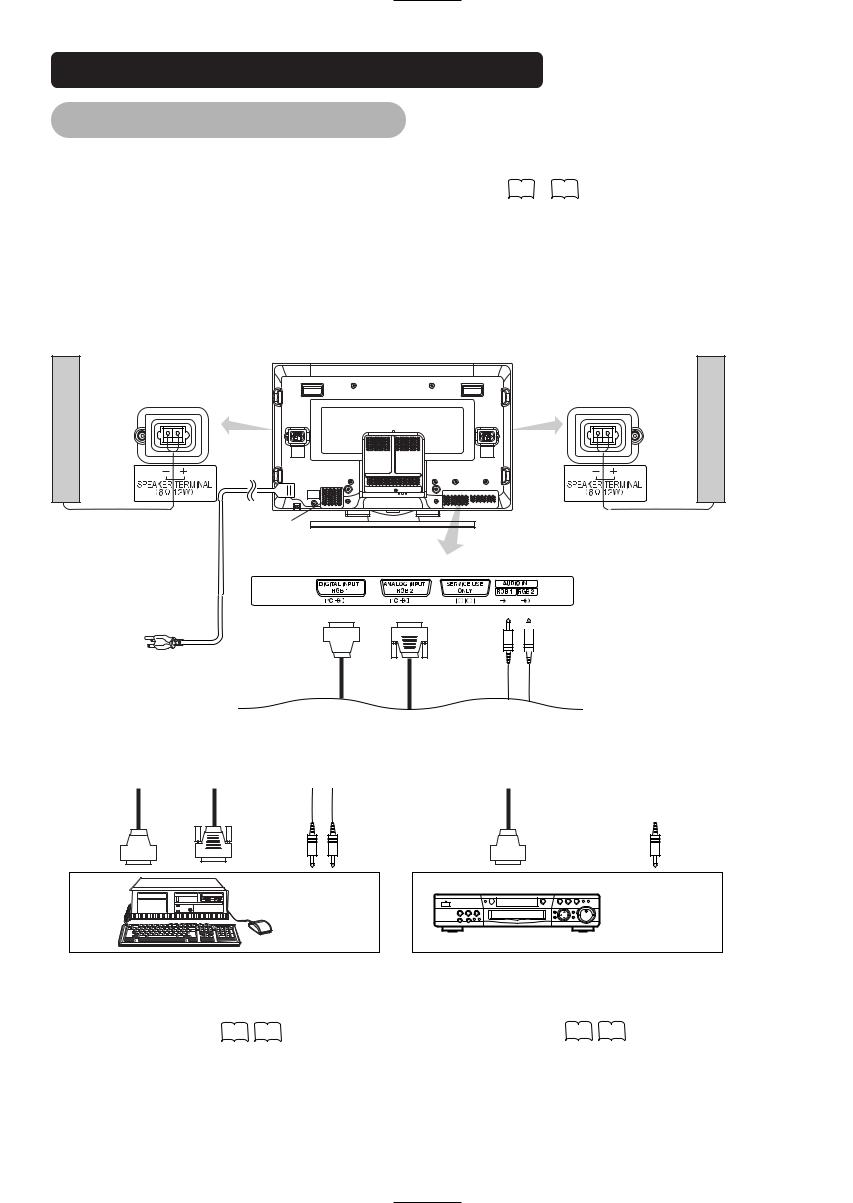
of connecting audio visual devices]
•AV1 SCART applies to composite/S-video, and AV2 SCART applies to composite/RGB.
•If a component input terminal and a composite input terminal of AV3 connect to the monitor at the same time, component input would govern.
•If video equipment with an S video output terminal is used, cabling by the S video cable is recommended to provide finer video quality. (If an S video input terminal and a video input terminal of AV4 (side input) connect to the monitor at the same time, S video input would govern.)
•If the OUTPUT (Monitor) terminal is connected to an external monitor with a 75 Ohm terminal, it is possible to view the same image as on the main unit. But it is possible to monitor only the composite video signal from AV1 ~ AV4 input that is displayed on the screen at the time.
•Whilst watching TV or DTT broadcasting, it is possible to switch between TV and DTT from AV1. At the time, SCART OUTPUT in Setup menu
need to be set to TV or DTT. Refer to 41 .
• Secure connecting cables to the stand with the provided clamp.
Common Interface*1
•Common interface allows you to receive Pay TV service with detachable modules.
•Inserting the common interface module:
1.Turn off the main power.
2.Insert the module all the way into the slot on the rear panel.
HDMI*2
• HDMI (High-Definition Multimedia Interface) is a digital interface based on DVI (Digital Visual Interface), which is an added function for audiovideo equipment.
–It does not have degradation by transmission since it is digital.
–With only one cable, it is possible to transmit both picture signals and audio signals.
• In case of using analogue audio, when connecting with DVI-HDMI transformation connector, use analogue audio terminal for AV3 input.
SCART Specification
|
CVBS |
S-video |
RGB |
AV1 |
|
|
— |
AV2 |
|
— |
|
13

INSTALLATION INSTRUCTIONS (continued)
feeder wire as interference
.
(not provided) for RF LEADS to
14
INSTALLATION INSTRUCTIONS (continued)
with the specifications of this
62 .
device to the display signal output
computer.
adapter or the adapter provided with manual of the personal computer or ask
Speaker (L)

 3.5mm Stereo
  mini jack
Audio Visual Device
To audio output terminal
(Example) DVD Player
61 |
62 |
to 60 |
61 . |
15
INSTALLATION INSTRUCTIONS (continued)

 CAUTION
Make sure that the main power switch of the monitor is turned off (standby mode or the indicating lamp: off/red) when removing or connecting the speaker cables.
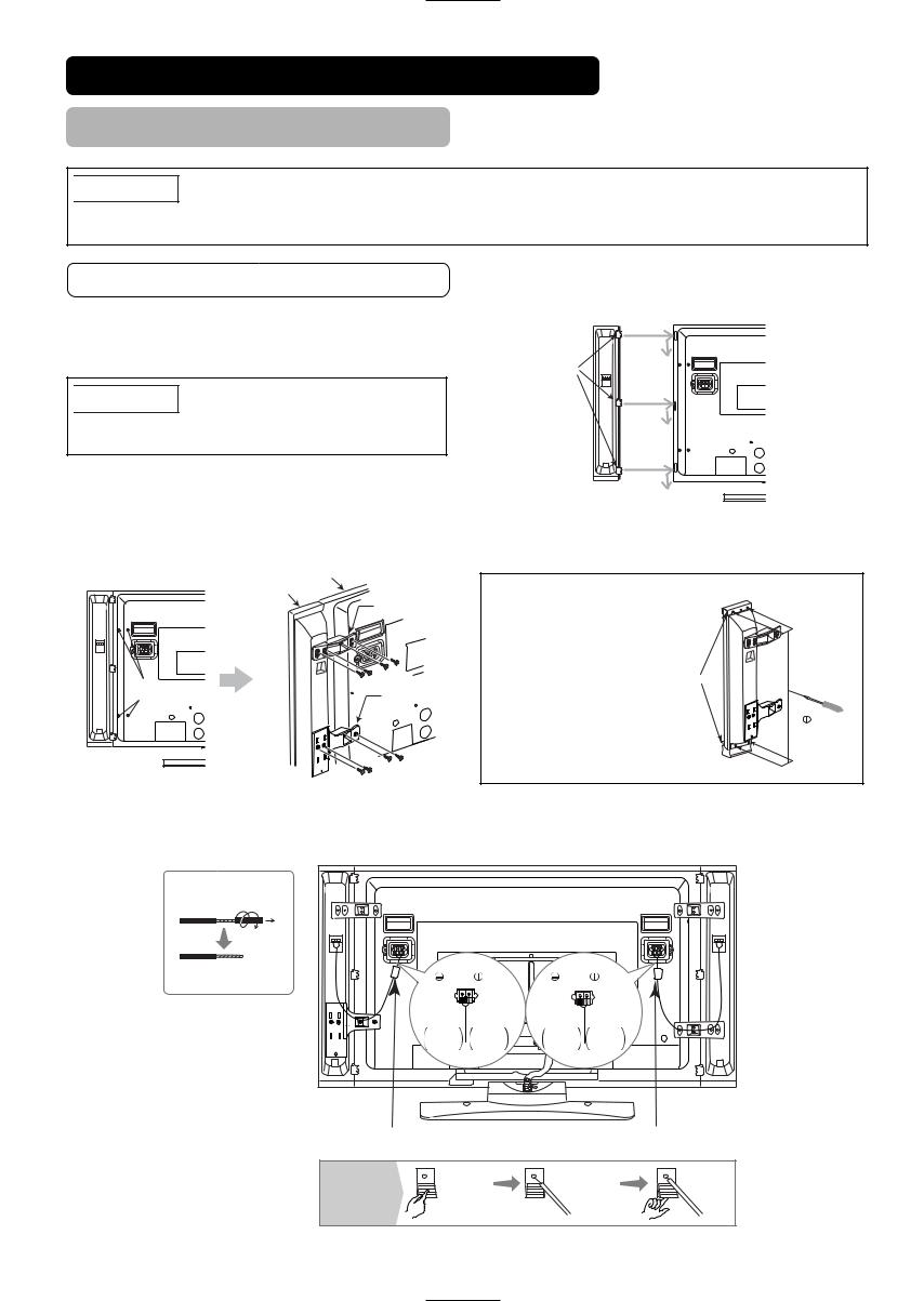
Mounting the Speaker System to the Monitor
1.Mounting the Speaker System to the Monitor.
Hook the clamps (3 pieces) into the holes as shown in the figure, and pull them down.
Follow the step for both Left and Right sides.
Right Side
Clamps

 CAUTION
Make sure to use the speaker systems fastened with the speaker holders and the screws.
Rear of the monitor
2.Attach the speaker holders.
After twisting the screws off as shown, fasten the speaker system to the monitor with the speaker holder by the screws. The speaker holder direction is opposite on the Right and Left speaker systems.
Right Side |
|
Monitor |
|
|
|
Speaker |
NOTE |
|
|
|
|
|
||
|
|
System |
|
|
|
|
Speaker holder |
In the event of the |
|
|
|
|
speakers not |
|
|
|
|
aligning correctly |
|
|
|
|
with the panel. |
|
|
|
Screws x 4 |
Loosen the screws |
Aluminum trims |
|
Twist off |
holding the aluminum |
|
|
|
Speaker holder |
|
||
|
the screws |
trims and adjust up or |
|
|
|
|
|
||
|
|
|
|
|
|
|
|
down to fit. |
Screwdriver |
|
|
|
|
Rear of the monitor
Screws x 4

 Place to attach the side input.
3. Attach the speaker connecting cables to the monitor. (Make sure the ferrite core is toward the monitor side.)
Treating the wire ends
Pull off whilst twisting
Please prepare the supplied speaker cables
(R) |
(L) |
||
Black |
Red |
Black |
Red |
Connect the |
Connect the |
Connect the |
Connect the |
silver |
copper |
silver |
copper |
colored wire |
colored wire |
colored wire |
colored wire |
Ferrite core |
|
|
Ferrite core |
|
How to connect |
Press down |
Insert the wire |
Raise |
|
the speaker |
||||
the lever |
|
lever |
||
cables |
|
|||
|
|
|
||
(Monitor side) |
|
|
|
16
INSTALLATION INSTRUCTIONS (continued)
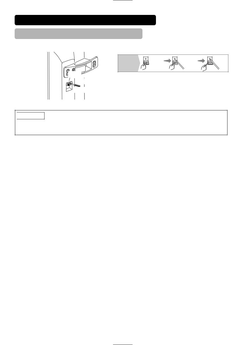
4. Attach the speaker cables to speaker systems.
How to connect the speaker cables (Speaker side)
Speaker terminals
Connect the copper colored wire to the  Red side.
Connect the silver colored wire to the  Black side.
Hold down |
Insert the wire |
Release |
the lever |
|
lever |

 CAUTION
Make sure to secure the power cable and the connecting cables for other audio visual devices, except the speaker connecting cables, to the clamps of the monitor stand and the rear of the monitor. When the monitor is swivelled, the connectors may drop out and generate heat. It could cause fire and/or connector failures.
17
INSTALLATION INSTRUCTIONS (continued)
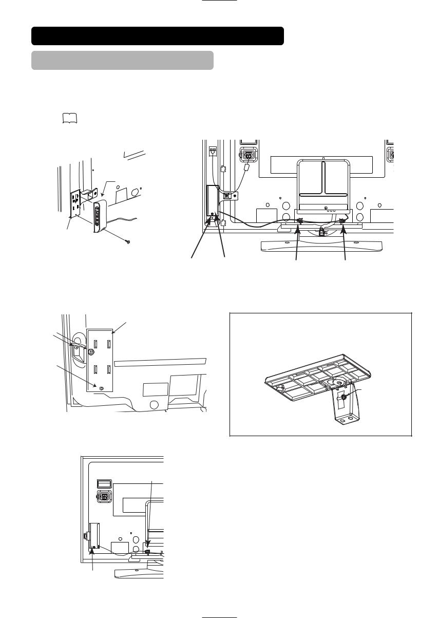
With the speaker unit
1. Mount the side input into the speaker holder.
Hook the clamps (4 pieces) of the speaker holder into the holes as shown in the figure and pull them down until it sounds click. Fasten the side input with the speaker holder by the screw.
Refer to 13 about the connection of side input. See the below figure how to treat the cable.
Side input
Speaker holder |
Screw x 1 |
Screw hole Side input |
Clamp |
Clamp |
Without the speaker unit
1. Attach the holder for the side input.
Holder
Screw x 2
Screw hole
2.Mount the side input into the securing holder.
Fasten the side input with the speaker holder by the screw. See the below figure how to treat the cable.
Clamp |
NOTE
About the fixing screw for the Side Input
•The screw for fixation is attached with the tape on the holder as shown below.
Screw
Side input
18
INSTALLATION INSTRUCTIONS (continued)
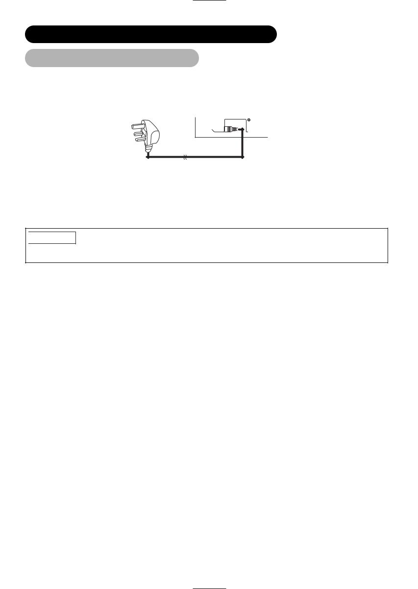
Power Cord Connection
.


 CAUTION
•Use only the power cord provided.
•Do not use a power supply voltage other than that indicated (AC220-240V, 50Hz) as this may cause fire or electric shock.
19
 Loading...