


Henny Penny
Pressure Fryer
Model PFG-690
TECHNICAL MANUAL
This manual should be retained in a convenient location for future reference.
A wiring diagram for this appliance is located on the rear shroud cover of the control panel.
Post in a prominent location, instructions to be followed if user smells gas. This information should be obtained by consulting the local gas supplier.
Do not obstruct the f ow of combustion and ventilation air. Adequate clearance must be left all around appliance for suff cient air to the combustion chamber.
The Model PFG-690 pressure fryer is equipped with a continuous pilot. But fryer cannot be operated without electric power. Fryer will automatically return to normal operation when power is restored.
Keep appliance area free and clear from combustibles.
Improper installation, adjustment, alteration, service or maintenance can cause property damage, injury or death. Read the installation, operating and maintenance
instructions thoroughly before installing or servicing this equipment.
DO NOT STORE OR USE GASOLINE OR OTHER FLAMMABLE VAPORS
AND LIQUIDS IN THE VICINITY OF THIS OR ANY OTHER APPLIANCE. FIRE OR EXPLOSION COULD RESULT.
810 |
FM06-006 |
Revised 8-12-10 |

HENNY PENNY
8 HEAD GAS PRESSURE FRYER
SPECIFICATIONS
Height |
61” (155 cm) |
Width |
24” (61 cm) |
Depth |
41¾” ( 106 cm) |
Floor Space |
Approximately 7 sq. ft. (0.65 sq. m.) |
Pot Capacity |
8 Head of chicken (32 lbs.) (14.4 kg.) |
|
130 lbs. shortening (59 kg.) |
Electrical |
120 VAC, 1 Phase, 50/60 Hz, 10 Amp, 3 Wire Service |
|
240 VAC, 1 Phase, 50/60 Hz, 5 Amp, 3 Wire Service |
Heating |
Propane or Natural Gas; 100,000 Btu/hr (105.51 MJ/hr) |
Pressure |
12 psi operating pressure (827 mbar) |
|
14.5 psi safety relief pressure (999 mbar) |
Shipping Weight |
Approximately 935 lbs. (424 kg.) |
A data plate, located on the back shroud behind the lid, gives the information of the type of fryer, serial number, warranty date, and other information pertaining to fryer. Also, the serial number is stamped on the outside of the frypot. See f gure below.
803

TABLE OF CONTENTS
Section |
|
|
|
|
|
|
Page |
Section 1. |
TROUBLESHOOTING.............................................................................................. |
|
|
|
1-1 |
||
|
1-1. |
Introduction .................................................................................................... |
|
|
|
|
1-1 |
|
1-2. |
Safety.............................................................................................................. |
|
|
|
|
1-1 |
|
|
1-3. |
Troubleshooting .............................................................................................. |
|
1-2 |
||
|
1-4. |
Error Codes .................................................................................................... |
|
|
|
|
1-11 |
Section 2. |
MAINTENANCE........................................................................................................ |
|
|
|
|
2-1 |
|
|
2-1. |
Introduction .................................................................................................... |
|
|
|
|
2-1 |
|
2-2. |
Maintenance Hints.......................................................................................... |
|
|
|
2-1 |
|
|
2-3. |
Preventive Maintenance |
................................................................................. |
|
2-1 |
||
|
2-4. |
High Temperature Limit Control.................................................................... |
|
2-2 |
|||
|
2-5. |
Power/Pump Switch ....................................................................................... |
|
|
|
2-4 |
|
|
2-6. |
Temperature Probe Replacement.................................................................... |
|
2-5 |
|||
|
2-7. |
Complete Control Panel - Henny Penny ........................................................ |
2-6 |
||||
|
2-8. |
Pressure Regulation........................................................................................ |
|
|
|
2-7 |
|
|
2-9. |
Tilting the Lid Upright ................................................................................... |
|
|
2-7 |
||
|
2-10. |
Reversing the Lid Gasket ............................................................................... |
|
2-8 |
|||
|
2-11. |
Lid Counterweight Cables.............................................................................. |
|
2-9 |
|||
|
2-12. |
Pressure Pad ................................................................................................... |
|
|
|
|
2-10 |
|
2-13. |
Lid Adjustment............................................................................................... |
|
|
|
2-11 |
|
|
2-14. |
Clean the Nylatrons........................................................................................ |
|
|
|
2-11 |
|
|
|
2-15. |
Solenoid |
Valve |
................................................................................................ |
2-12 |
|
|
2-16. |
Deadweight Valve........................................................................................... |
|
|
|
2-14 |
|
|
2-17. |
Removal & Cleaning of Safety Relief Valve.................................................. |
2-15 |
||||
|
2-18. |
Pressure Gauge............................................................................................... |
|
|
|
2-16 |
|
|
2-19. |
Gas Control Valve .......................................................................................... |
|
|
|
2-17 |
|
|
2-20. |
Blower Assembly ........................................................................................... |
|
|
|
2-19 |
|
|
2-21. |
Transformer .................................................................................................... |
|
|
|
|
2-20 |
|
|
2-22ow. SwitchAirf............................................................................................... |
|
|
|
2-21 |
|
|
|
2-23. |
Drain |
|
Microswitch .......................................................................................... |
2-22 |
|
|
2-24. |
Drain Valve and Extension............................................................................. |
|
2-23 |
|||
|
|
2-25. |
Air |
Valve......................................................................................................... |
|
2-24 |
|
|
2-26. |
Cleaning the Dilution Box.............................................................................. |
|
2-25 |
|||
|
2-27. |
Cleaning the Blower Wheel ........................................................................... |
|
2-25 |
|||
|
|
2-28. |
Ignition |
Modules |
............................................................................................ |
2-26 |
|
|
|
2-29. |
Ignitor |
|
Assembly |
............................................................................................ |
2-27 |
|
|
2-30. |
Flame |
|
Sensor |
Assembly ................................................................................. |
2- |
|
2-31. |
Ignitor and Flame Sensor Adjustment............................................................ |
2-28 |
||||
|
2-32. |
Nylatron Strips Replacement ......................................................................... |
|
2-29 |
|||
|
2-33. |
Lubricating Lid Rollers .................................................................................. |
|
|
2-30 |
||
|
|
120 Volt Wiring Diagram (AP0803002 & BELOW) ..................................... |
2-31 |
||||
|
|
120 Volt Wiring Diagram (AP0803003 & ABOVE)...................................... |
2-32 |
||||
|
|
220-240 Volt Wiring Diagram (AP0803002 & BELOW).............................. |
2-33 |
||||
|
|
220-240 Volt Wiring Diagram (AP0803003 & ABOVE)............................... |
2-34 |
||||
|
|
230 Volt Wiring Diagram (AP0803002 & BELOW) ..................................... |
2-35 |
||||
|
|
230 Volt Wiring Diagram (AP0803003 & ABOVE)...................................... |
2-36 |
||||
810 |
|
|
|
|
|
|
i |

TABLE OF CONTENTS (Continued)
Section |
|
Page |
Section 2 |
MAINTENANCE (Continued) |
|
|
230 Volt Ladder Diagram (AP0803002 & BELOW)..................................... |
2-37 |
|
230 Volt Ladder Diagram (AP0803003 & ABOVE)...................................... |
2-38 |
|
100-120 Volt FAST Wiring Diagram (AP0803002 & BELOW) ................... |
2-39 |
|
100-120 Volt FAST Wiring Diagram (AP0803003 & ABOVE) .................... |
2-40 |
|
230 Volt FAST Wiring Diagram (AP0803002 & BELOW)........................... |
2-41 |
|
230 Volt FAST Wiring Diagram (AP0803003 & ABOVE) ........................... |
2-42 |
|
220-240 Volt FAST Wiring Diagram (AP0803002 & BELOW) ................... |
2-43 |
|
220-240 Volt FAST Wiring Diagram (AP0803003 & ABOVE) .................... |
2-44 |
Section 3. PARTS INFORMATION............................................................................................. |
3-1 |
|
3-1. |
Introduction .................................................................................................... |
3-1 |
3-2. |
Genuine Parts ................................................................................................. |
3-1 |
3-3. |
When Ordering Parts...................................................................................... |
3-1 |
3-4. |
Prices .............................................................................................................. |
3-1 |
3-5. |
Delivery.......................................................................................................... |
3-1 |
3-6. |
Warranty ......................................................................................................... |
3-1 |
3-7. Recommended Spare Parts for Distributors................................................... |
3-2 |
|
ii |
810 |
SECTION 1. TROUBLESHOOTING
1-1. INTRODUCTION
1-2. SAFETY
103
This section provides troubleshooting information in the form of an easy-to-read table.
If a problem occurs during the f rst operation of a new fryer, recheck the installation per the Installation section of the Operator’s Manual.
Before troubleshooting, always recheck the operation procedures per section 3 of the Operator’s Manual.
Where information is of particular importance or safety related, the words DANGER, WARNING, CAUTION, and NOTICE are used. Their usage is described below.
SAFETY ALERT SYMBOL is used with DANGER, WARNING, or CAUTION which indicates a personal injury type hazard.
NOTICE is used to highlight especially important information.
CAUTION used without the safety alert symbol indicates a potentially hazardous situation which, if not avoided, may result in property damage.
CAUTION indicates a potentially hazardous situation which, if not avoided, may result in minor or moderate injury.
WARNING indicates a potentially hazardous situation which, if not avoided, could result in death or serious injury.
DANGER INDICATES AN IMMINENTLY HAZARDOUS SITUATION WHICH, IF NOT AVOIDED, WILL RESULT IN DEATH OR SERIOUS INJURY.
1-1

1-3. TROUBLESHOOTING |
To isolate a malfunction, proceed as follows: |
1.Clearly def ne the problem (or symptom) and when it occurs.
2.Locate the problem in the Troubleshooting table.
3.Review all possible causes. Then, one at a time, work through the list of corrections until the problem is solved.
4.Refer to the maintenance procedures in the Maintenance section to safely and properly make the checkout and re-
pair |
needed. |
If maintenance procedures are not followed correctly, injuries and/or property damage could result.
1-2

1-3. TROUBLESHOOTING (Continued)
Problem |
Cause |
Correction |
|
|
|
COOKING SECTION |
|
Product Color Not Correct: |
|
|
|
A. Too Dark |
• Temperature too high |
• Check temperature setting |
|
|
|
|
in the program mode; see |
|
|
|
Programming section of |
|
|
|
Operator’s Manual |
|
|
• Faulty temperature probe |
• Remove and replace tempera- |
|
|
|
ture probe |
|
|
• Shortening too old |
• Change shortening |
|
|
• Shortening too dark |
• Filter shortening |
|
|
|
• Change shortening |
|
|
• Breading product too far |
• Bread product closer to |
|
|
in advance |
actual frying period |
B. Too Light |
• Temperature too low |
• Check temperature setting |
|
|
|
|
• Remove and replace tempera- |
|
|
|
ture probe |
|
|
• Fryer incorrect preheat |
• Allow proper preheat time |
|
|
• Slow fryer heat-up/recovery |
• Low gas pressure; have gas |
|
|
|
pressure checked going to |
|
|
|
burners |
|
|
• Wrong cook button |
• Be sure to select the correct |
|
|
pushed |
amount of product to be cooked |
C. Product |
• Shortening old |
• Replace shortening |
Greasy |
|
|
|
• Temperature too low |
• Check temperature setting |
|
|
• Temperature not recovered |
|
|
when product was dropped |
|
|
in frypot |
|
• Faulty temperature probe |
• Remove and replace defective |
|
|
temperature probe |
|
• Frypot overloaded |
• Reduce cooking load |
|
• Product not removed from |
•Remove product from |
|
frypot immediately after |
frypot immediately after |
|
depressurization |
depressurization |
1002 |
|
1-3 |

1-3. TROUBLESHOOTING
(Continued) |
|
|
|
|
|
|
|
|
|
Problem |
Cause |
|
Correction |
|
|
|
|
|
|
|
COOKING SECTION (Continued) |
|
|
|
|
|
|
|
|
D. Spotted |
• Improper separation of the |
|
• Load product into basket |
|
Product |
product |
|
properly |
|
|
• Breading not uniform on |
|
• Sift breading regularly |
|
|
the product |
|
• Separate product during |
|
|
|
|
breading |
|
|
• Burned breading particles |
|
• Filter the shortening more |
|
|
on product |
|
frequently |
|
|
• Product sticking together |
|
• Separate product prior to |
|
|
|
|
pressure cooking |
|
E. Dryness of |
|
|
|
|
• Moisture loss prior to |
|
• Use fresh products |
||
Product |
cooking |
|
|
|
|
• Overcooking the product |
|
• Reduce cooking time |
|
|
|
|
• Reduce cooking |
|
|
|
|
temperature |
|
|
• Low operating pressure |
|
• Check pressure gauge reading, |
|
|
|
|
check for pressure leaks |
|
|
• Wrong cook button pushed |
|
• Be sure to select the |
|
|
|
|
correct amount of |
|
|
|
|
product to be cooked |
|
Product Flavor (Taste): |
• Breading mixture is too salty |
|
• Sift breading after each use |
|
A. Salty Taste |
|
|||
|
|
|
• Incorrect breading mixture |
|
|
|
|
• Discard old breading |
|
|
• Incorrect choice of |
|
• Use breading designed for |
|
|
breading |
|
the desired product |
|
B. Burned Taste |
• Burned shortening f avor |
|
• Replace shortening |
|
|
• Frypot not properly cleaned |
|
• Drain and clean frypot |
|
C. Bland Taste |
• Raw product not fresh |
|
• Use fresh raw product |
|
|
• Breading mixture incorrect |
|
• Use breading designed for |
|
|
for product (spice content |
|
desired product |
|
|
too low) |
|
|
|
|
• Cooking temperature too |
|
• Check temperature |
|
|
high (spice f avors lost) |
|
|
|
1-4 |
|
|
1002 |
|
1-3. TROUBLESHOOTING (Continued)
|
Problem |
Cause |
|
Correction |
|
|
|
|
|
|
|
|
|
|
COOKING SECTION (Continued) |
|
|
D. Rancid Taste |
|
• Shortening too old |
|
• Replace shortening and |
|
|
|
|
|
|
follow recommended care |
|
|
|
|
|
and use of shortening |
|
|
|
• Infrequent f ltering |
|
• Replace shortening and |
|
|
|
|
|
follow recommended care |
|
|
|
|
|
and use of shortening |
|
|
|
• Non-compatible products |
|
• Replace shortening |
|
|
|
cooked within the same |
|
• Use compatible products |
|
|
|
shortening |
|
and follow recommended care |
|
|
|
|
|
and use of shortening |
|
|
|
• Raw product not fresh |
|
• Use fresh product |
|
|
|
|
|
|
General: |
|
• Incorrect meat cut |
|
• Use correct meat cutting |
|
|
|
|
|
|
procedures |
A. Meat Separation |
|
• Overcooking |
|
• Check cooking time |
|
|
From Bone |
|
• Product not fresh |
|
• Use fresh product |
B. Bone Color |
|
|
|
|
|
|
• Using frozen product |
|
• Use fresh product |
||
|
Not Proper |
|
(black bone) |
|
|
|
|
|
• Improper processing of |
|
• Use proper processing |
|
|
|
product (black bone) |
|
procedure for product |
|
|
|
• Product not thoroughly |
|
• Check cooking time |
|
|
|
cooked (red bone) |
|
• Check cooking temperature |
|
|
|
|
|
|
C. Breading Falls |
|
• Incorrect breading |
|
• Use correct breading |
|
|
Off |
|
procedures |
|
procedure |
|
|
|
• Product partially frozen |
|
• Thoroughly thaw the |
|
|
|
|
|
product before breading |
|
|
|
|
|
|
D. Product |
|
• Product breaded too long |
|
• Refer to breading and |
|
|
Sticking |
|
prior to cooking |
|
frying instructions |
|
Together |
|
• Improper loading |
|
• Properly load product per |
|
|
|
|
||
|
|
|
procedure |
|
loading procedures |
|
|
|
• Wrong cook button pushed |
|
• Be sure to select the |
|
|
|
|
|
correct amount of product |
|
|
|
|
|
to be cooked |
1002 |
|
|
|
1-5 |
|
|
|
|
|||

1-3. TROUBLESHOOTING (Continued)
Problem |
Cause |
Correction |
|
POWER SECTION |
|
With switch in |
• Open circuit |
• Check to see that unit is |
POWER position, |
|
plugged in |
the fryer is com- |
|
• Check the breaker or fuse |
pletely inoperative |
|
at supply box |
(NO POWER) |
|
• Check voltage at wall |
|
|
receptacle |
|
|
• Check MAIN POWER |
|
|
switch; replace if defective |
|
|
• Check cord and plug |
|
|
|
|
PRESSURE SECTION |
|
|
|
|
Pressure will not |
• Exhaust line from solenoid |
• Turn unit off and allow |
exhaust at end of |
valve to exhaust tank |
fryer to cool to release |
cook cycle |
clogged |
pressure from frypot; |
|
|
clean all pressure lines, |
|
|
exhaust stacks, and exhaust |
|
|
tank |
|
• Solenoid valve clogged |
• Check and clean solenoid |
|
|
valve per maintenance |
|
|
section on solenoid valve |
|
|
|
Operating |
• Dead weight clogged |
• Turn unit off and allow |
pressure too high |
|
fryer to cool to release |
|
|
pressure from frypot; |
|
|
remove deadweight and |
|
|
clean |
|
• Exhaust line to stack clogged |
• Clean exhaust line to stack |
|
|
|
DO NOT OPERATE UNIT IF HIGH-PRESSURE CONDITIONS EXIST; SEVERE INJURIES AND BURNS WILL RESULT. PLACE POWER/PUMP SWITCH IN THE OFF POSITION IMMEDIATELY. RELEASE THE PRESSURE BY ALLOWING UNIT TO COOL. THE PRESSURE WILL THEN DROP. DO NOT RESUME USE OF UNIT UNTIL CAUSE OF HIGH PRESSURE HAS BEEN FOUND AND CORRECTED.
1-6 |
1002 |

1-3. TROUBLESHOOTING (Continued)
Problem |
Cause |
|
Correction |
|
|
|
|
|
|
|
PRESSURE SECTION (Continued) |
|
|
|
|
|
|
|
|
Pressure does not |
• Not enough product in fryer |
|
• Place proper quantity of |
|
build |
or product not fresh |
|
fresh product within |
|
|
|
|
frypot to generate steam |
|
|
• Metal shipping spacer not |
|
• Remove shipping spacer; |
|
|
removed from deadweight |
|
see Unpacking section of |
|
|
|
|
Operator’s Manual |
|
|
• Lid open or not latched |
|
• Close and latch lid |
|
|
• Solenoid valve leaking or |
|
• Check or clean solenoid |
|
|
not closing |
|
valve per maintenance |
|
|
|
|
section on the solenoid valve |
|
|
• Deadweight valve leaking |
|
• Repair per maintenance sec- |
|
|
|
|
tion on deadweight valve |
|
|
• Pressure not programmed |
|
• Check programming |
|
|
• Lid gasket leaking |
|
• Reverse gasket or lid needs |
|
|
|
|
adjusted; see sections 2-10 & |
|
|
|
|
2-13 |
|
|
• Safety relief valve leaking |
|
• Check and replace if |
|
|
|
|
necessary per maintenance |
|
|
|
|
section on the safety relief |
|
|
|
|
valve |
|
|
• Pressure pad broken or crushed |
|
• Replace pressure pads |
|
|
|
|
|
|
1002 |
1-7 |

1-3. TROUBLESHOOTING (Continued)
Problem |
Cause |
Correction |
HEATING OF SHORTENING SECTION
Shortening will not heat |
• Gas valve knob turned to the OFF |
|
|
|
position |
|
• |
Blown fuse or tripped |
|
|
circuit breaker at supply |
|
|
box or control panel |
|
• Blown fuse in PC board |
|
|
• Faulty Power/Pump switch |
|
|
• |
Faulty cord and plug |
|
• |
Faulty drain switch |
|
• |
Faulty PC Board |
|
• |
Faulty high limit control switch |
|
• |
Drain valve open |
|
• |
Possible faulty gas control |
|
|
valve |
|
• |
Possible faulty temperature probe |
|
• |
Bad spark ignitor |
|
• |
Low air pressure |
|
• |
Faulty ignitor module |
|
• |
Spark ignitor or f ame sensor out of |
|
|
adjustment |
|
|
|
•Make sure the gas valve knob is turned to the ON position
•Reset breaker or replace fuse
•Replace glass fuse in board
•Check Power/Pump switch
per maintenance section on the Power/Pump switch
•Check cord and plug and power at wall receptacle
•Check drain switch per maintenance section on drain switches
•Remove and replace control panel
•Check high limit control switch per maintenance section on the high limit
•Close drain valve
•With power removed from fryer, check across elec-
trical leads of gas control valve with multimeter, and gas valve in ON position
•Replace temperature probe
•Replace spark ignitor
•Clean or replace blower
•Replace air pressure switch
•Replace module
•The spark ignitor must be 1/8 inch from the pilot hood, and 1/4 inch from the f ame sensor
1-8 |
1002 |

1-3. TROUBLESHOOTING (Continued)
Problem |
|
Cause |
Correction |
|
|
HEATING OF SHORTENING SECTION (Continued) |
|
||
|
|
|
|
|
Heating of |
|
• Supply line too small - low |
• Increase supply line size; |
|
shortening too |
|
gas volume |
refer to installation |
|
slow |
|
|
instructions |
|
|
|
• Improper ventilation |
• Refer to installation |
|
|
|
system |
instructions |
|
|
|
|
• Observe burners |
|
|
|
|
• Check gas pressure |
|
|
|
|
• Clean dilution box; refer to |
|
|
|
|
section 2-25 |
|
|
|
• Burner out of adjustment |
• Clean blower wheel; refer to |
|
|
|
|
section 2-26 |
|
|
|
|
|
|
Shortening |
|
• Programming wrong |
• Check temperature setting |
|
overheating |
|
|
in the program mode |
|
|
|
• Faulty PC Board |
• Remove and replace control |
|
|
|
|
panel |
|
|
|
• Faulty temperature probe |
• Remove and replace tempera- |
|
|
|
|
ture probe |
|
|
|
|
|
|
1002 |
1-9 |

1-3. TROUBLESHOOTING (Continued)
Problem |
|
|
Cause |
Correction |
|
SHORTENING FOAMING/DRAINING SECTION |
|||
|
|
|
|
|
Foaming or boil- |
|
|
• Water in shortening |
• At end of a cook cycle, |
ing over of |
|
|
|
drain shortening and clean |
shortening |
|
|
|
frypot; add fresh |
|
|
|
|
shortening |
|
|
|
• Condensation line stopped up |
• Remove and clean conden- |
|
|
|
|
sation line |
|
|
|
• Improper or bad |
• Use recommended |
|
|
|
shortening |
shortening |
|
|
|
• Improper f ltering |
• Refer to the procedure |
|
|
|
|
covering f ltering the |
|
|
|
|
shortening |
|
|
|
• Cold zone full of cracklings |
• Filter shortening |
|
|
|
• Improper rinsing after |
• Clean and neutralize the |
|
|
|
cleaning the fryer |
frypot; rinse with vinegar |
|
|
|
|
to remove the alkaline, then |
|
|
|
|
rinse with hot water, and |
|
|
|
|
dry frypot |
|
|
|
|
|
Shortening will |
|
|
• Drain valve clogged with |
• Open valve, push cleaning |
not drain from |
|
|
crumbs |
rod through drain open- |
frypot |
|
|
|
ing from inside of frypot |
Shortening leaking |
• Obstruction in drain |
• Remove obstruction |
through drain |
|
|
valve |
|
|
|
• Faulty drain valve |
• Replace drain valve |
1-10 |
1002 |

1-4. ERROR CODES |
In the event of a control system failure, the digital display shows |
|||
|
|
an error message. These messages are coded: “E-4”, “E-5”, “E-6”, |
||
|
|
“E-32”, “E-41” and “E-71”. A constant tone is heard when an |
||
|
|
error code is displayed, and to silence this tone, press any of the |
||
|
|
product buttons. |
|
|
|
|
|
|
|
DISPLAY |
CAUSE |
|
PANEL BOARD CORRECTION |
|
“E-4” |
Control board overheating |
Turn switch to OFF position, then turn |
||
|
|
|
switch back to ON; if display still shows |
|
|
|
|
“E-4”, the board is getting too hot; check for |
|
|
|
|
signs of overheating behind the control |
|
|
|
|
panel; once panel cools down the controls |
|
|
|
|
should return to normal; if “E-4” persists, |
|
|
|
|
have control panel replaced |
|
|
|
|
||
“E-5” |
Shortening overheating |
Turn switch to OFF position, then back to |
||
|
|
|
ON; if display shows “E-5”, the heating |
|
|
|
|
circuits and temperature probe should be |
|
|
|
|
checked; once the unit cools down, the |
|
|
|
|
controls should return to normal; if “E-5” |
|
|
|
|
persists, have control panel replaced |
|
|
|
|
||
“E-6” |
Temperature probe failure |
Turn switch to OFF position, then back to |
||
|
|
|
ON; if the display shows “E-6”, the tempera- |
|
|
|
|
ture probe should be checked; once the |
|
|
|
|
probe is repaired, or replaced, the controls |
|
|
|
|
should return to normal; if “E-6” persists, |
|
|
|
|
have control panel replaced |
|
|
|
|
||
“E-41” |
Programming failure |
Turn switch to OFF position, then back to |
||
|
|
|
ON; if display shows “E-41”, the control |
|
|
|
|
should be re-initialized (See Programming |
|
|
|
|
Section) if the error code persists, have |
|
|
|
|
control panel replaced |
|
“E-71” |
|
|
||
Pump motor relay failure or |
Replace relay if contacts are stuck closed; |
|||
|
wiring problem |
|
check wiring on POWER/PUMP switch, or at |
|
|
|
|
wall receptacle; L1 and N may be reversed |
|
“E32, CHECK |
|
|
||
Air pressure switch open; clogged |
Clean dilution box or replace blower if |
|||
HIGH LIMIT, |
dilution box or faulty blower; open |
necessary; have drain switch checked; reset |
||
DRAIN VALVE, |
drain switch; open high limit; open |
high limit or have high limit checked; check |
||
VACUUM |
||||
vacuum switch |
|
vacuum switch |
||
SWITCH, |
|
|||
BLOWER MOTOR |
|
|
|
|
|
|
|
|
|
806 |
1-11 |

1-4. ERROR CODES (Continued)
|
|
CE Only - Along with error codes from preceding page, CE |
|
|
|
units have the following self-diagnostic error codes: |
|
|
|
|
|
DISPLAY |
CAUSE |
|
PANEL BOARD CORRECTION |
“E-10” |
High limit |
|
Allow unit to cool (15-20 minutes), reset the high limit by |
|
|
|
manually pushing up on red reset button; if high limit does |
|
|
|
not reset, high limit must be replaced per section 2-4 |
|
|
|
|
“E-15” |
Drain Switch |
|
Close the drain using drain valve handle; if display still |
|
|
|
shows “E-15,” check the drain microswitch per section 2-22 |
|
|
|
|
“E-20A” |
Air Pressure |
|
Press the Timer button to try the ignition process again; |
|
Switch Failure |
|
if “E-20A” persists, call Henny Penny’s Service Depart- |
|
(stuck closed) |
|
ment |
|
|
|
|
“E-20B” |
Draft Fan or |
|
Press the Timer button to try the ignition process again; if |
|
Air Pressure |
|
“E-20B” persists, call Henny Penny’s Service Department; |
|
(stuck open) |
|
Switch Failure Number of failures can be seen in Review |
|
|
|
Usage (pg. 3-24) of Operator’s Manual, then press EXIT |
|
|
|
COOL |
“E-20C” |
Left Gas Module |
|
Press the Timer button to try the ignition process again; if |
|
Failure |
|
“E-20C” persists, call Henny Penny’s Service Department |
|
|
|
|
“E-20D” |
Right Module |
|
Press the Timer button to try the ignition process again; if |
|
Failure |
|
“E-20D” persists, call Henny Penny’s Service Department |
|
|
|
|
“E-20E” |
Both Modules |
|
Press the Timer button to try the ignition process again; if |
|
Failure |
|
“E-20E” persists, call Henny Penny’s Service Department |
|
|
|
|
“E-20F” |
Left Module |
|
Press the Timer button to try the ignition process again; if |
|
No Flame Sense |
|
“E-20F” persists, call Henny Penny’s Service Department |
|
|
|
|
“E-20G” |
Right Module |
|
Press the Timer button to try the ignition process again; if |
|
No Flame Sense |
|
“E-20G” persists, call Henny Penny’s Service Department |
|
|
|
|
“E-20H” |
Both Modules |
|
Press the Timer button to try the ignition process again; if |
|
No Flame Sense |
|
“E-20H” persists, call Henny Penny’s Service Department |
|
|
|
|
1-12 |
810 |

SECTION 2. MAINTENANCE |
||
|
|
|
2-1. INTRODUCTION |
This section provides checkout and replacement procedures for |
|
|
various parts of the fryer. Before replacing any parts, refer to |
|
|
the Troubleshooting section to aid you in f nding the cause of |
|
|
the malfunction. |
|
2-2. MAINTENANCE HINTS |
1. A multimeter will help you check the electric components. |
|
|
2. When the manual refers to the circuit being closed, the |
|
|
multimeter should read zero unless otherwise noted. |
|
|
3. When the manual refers to the circuit being open, the |
|
|
multimeter should read inf nity. |
|
|
Do not move the fryer with hot shortening in the frypot |
|
|
or drain filter pan. Severe burns can result from |
|
|
splashing hot shortening. |
|
|
4. Remove weights from frame to easily access rear of fryer. |
|
2-3. PREVENTIVE |
To ensure a long life of fryers and their components, regular |
|
MAINTENANCE |
maintenance should be performed. Refer to the chart below. |
|
|
Frequency |
Action |
|
Daily |
Clean deadweight assembly cap, weight, |
|
|
and deadweight orif ce (see section 2-15) |
|
See KFC’s |
Filtering of shortening |
|
Standards Library |
|
|
Monthly |
Check dilution box, clean as needed |
|
|
(see section 2-25) |
|
Monthly |
Clean the Nylatrons (see section 2-14) |
|
Annually |
Clean blower wheel (see section 2-26) |
|
Annually |
Lubricate lid rollers in back of fryer |
|
|
(see section 2-32) |
|
Annually |
Remove and clean safety relief valve |
|
|
(see section 2-16) |
|
See KFC’s |
Cleaning the frypot |
|
Standards Library |
|
|
Every 90 Days |
Reversing lid gasket (see section 2-10) |
810 |
|
2-1 |

2-4. HIGH TEMPERATURE |
|
LIMIT CONTROL |
This high temperature control is a safety, manual reset control, |
|
which senses the temperature of the shortening. If the shorten- |
|
ing temperature exceeds 425°F (218°C), this switch opens and |
|
shuts off the heat to the frypot. When the temperature of the |
|
shortening drops to a safe operation limit (15-20 minutes), |
|
manually reset by pressing the red reset button. The red reset |
|
button is located under the control panel, in the front of the |
|
fryer. Once reset, the frypot starts heating. |
|
Before replacing a high temperature limit control, check to see |
|
that its circuit is closed. |
Checkout
The shortening temperature must be below 380°F (193°C) to accurately perform this check.
1.Remove electrical power supplied to the fryer.
To avoid electrical shock or property damage, move the power switch to OFF and disconnect main circuit breaker, or unplug cord at wall receptacle.
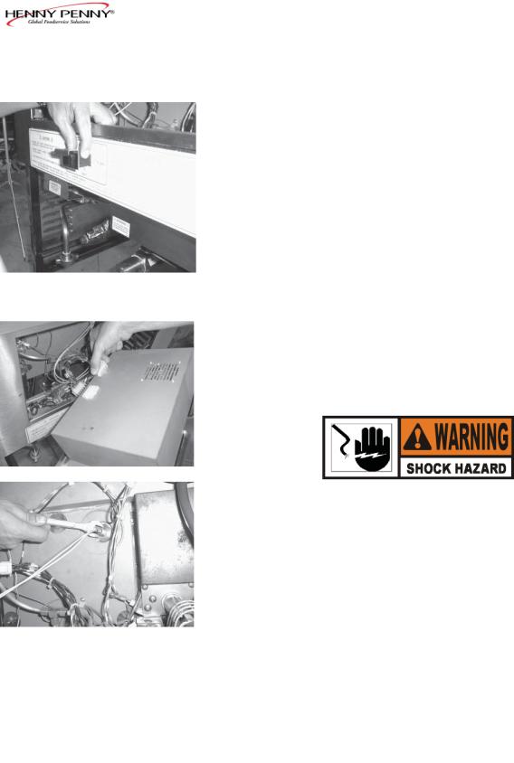
2.Remove the control panel.
3.Remove the two nuts securing high limit bracket to the unit, and pull the bracket from the unit.
4.Remove the two screws securing the high limit to bracket, and remove the high limit from the bracket.
5.Remove the two electrical wires from the high temperature limit control.
6.Manually reset the control, then check for continuity between the two terminals after resetting the control. If the circuit is open, replace the control, then continue with this procedure. (If the circuit is closed, the high limit is not defective. Reconnect the two electrical wires.)
2-2 |
810 |
2-4. HIGH TEMPERATURE
LIMIT CONTROL
(Continued) |
|
Replacement |
To avoid electrical shock or property damage, move the |
|
power switch to OFF and disconnect main circuit |
|
breaker, or unplug cord at wall receptacle. |
1. |
If the tube is broken or cracked, the control will open, |
|
shutting off electrical power. The control cannot be reset. |
2. |
Drain shortening from the frypot and discard. A substance |
|
in the tube could contaminate the shortening. |
3. |
Remove control panel. |
4. |
Loosen small inside screw nut on capillary tube. |
5. |
Remove capillary bulb from bulb holder inside the frypot. |
6. |
Straighten the capillary tube. |
7. |
Remove larger outside nut that threads into pot wall, and |
|
remove defective control from control panel area. |
8. |
Insert new control and replace screws. |
9. |
Uncoil capillary line, starting at capillary tube, and insert |
|
through frypot wall. |
|
To avoid electrical shock or other injury, run the capillary |
|
line under and away from all electrical power wires and |
|
terminals. The tube must NEVER be in such a position |
|
where it could accidentally touch the electrical power |
|
terminals. |
10. |
Carefully bend the capillary tube as shown in photo and place |
|
into bulb brackets. |
1002 |
2-3 |
2-4. HIGH TEMPERATURE |
11. Pull all excess capillary line from the frypot and tighten nut |
||
LIMIT CONTROL |
|
into frypot |
wall. |
(Continued) |
|
|
|
|
|
Be sure capillary bulb of high limit is positioned so it does |
|
|
|
not interfere with the carrier or get damages when clean- |
|
|
|
ing the frypot. |
|
|
12. |
With excess capillary line pulled out, tighten smaller nut. |
|
|
13. |
Replace front panel. |
|
|
14. |
Ref ll with shortening. |
|
2-5. POWER/PUMP SWITCH |
The Power/Pump switch is a three-way rocker switch with a |
||
|
center OFF position. With the switch in the POWER position, |
||
|
the fryer operates. With the switch in the PUMP position, the |
||
|
f lter pump operates, but the unit will not heat. |
||
To avoid electrical shock or property damage, move the power switch to OFF and disconnect main circuit breaker, or unplug cord at wall receptacle.
Checkout
1.Remove Control Panel.
2.Label and remove wires from the switch.
3.“OFF” Position - should be open circuit anywhere on the switch.
4.“Power” Position. Check from:
5.“Pump” Position. Check from:
#5 to #6 closed circuit #l to #2 closed circuit
#4 to #5 closed circuit #3 to #2 closed circuit
Check across the jumpers on the wires of the Power/Pump switch. These jumpers have resistors and capacitors which may be faulty.
2-4 |
1002 |
2-5. |
POWER/PUMP SWITCH |
|
|
|
(Continued) |
|
|
|
Replacement |
|
|
|
|
1. With control panel removed, and wires off the switch, |
|
|
|
|
push in on tabs on the switch to remove from the panel. |
|
|
2. Replace with new switch, and reconnect wires to switch |
|
|
|
|
following the wiring diagram. |
|
|
3. Replace the control panel. |
|
2-6. |
TEMPERATURE PROBE |
TemperatureProberelaystheactualshorteningtemperature |
|
|
REPLACEMENT |
to the control. If it becomes disabled, “E-6” will show in the |
|
|
|
display. Also, if the temperature is out of calibration more than |
|
|
|
10°F, or 10°C, the temperature probe should be replaced. An |
|
|
|
Ohm check can be performed also. See chart at end of this |
|
|
|
section. |
|
|
|
1. |
Remove electrical power supplied to the fryer. |
|
|
|
To avoid electrical shock or property damage, move the |
|
|
|
power switch to OFF and disconnect main circuit |
|
|
|
breaker, or unplug cord at wall receptacle. |
|
|
2. |
Drain the shortening from the frypot. |
|
|
3. |
Remove the Control Panel. |
|
|
4. |
Using a 1/2” wrench, remove the nut on the compression |
|
|
5. |
Remove the temperature probe from the frypot. |
6.
Figure |
2-1 |
Place nut and new ferrule on new temperature probe and insert the temperature probe into the compression f tting until it extends 1/2 inch (1.3 cm) into the frypot. Use the temperature probe gauge provided in the temperature probe kit to ensure proper placement in frypot. See Figures 2-1 and 2-2.
806 |
2-5 |

2-6. TEMPERATURE PROBE 7. Tighten hand tight and then a half turn with wrench.
REPLACEMENT (Continued)
Excess force will damage temperature probe.
8. Connect new temperature probe to PC board and replace Control Panel.
9.Replace shortening.
10.Turn power ON and check out fryer.
Figure 2-2
2-7. COMPLETE CONTROL Should the Control Panel become inoperative, follow these PANEL - HENNY PENNY instructions for replacing the board.
1.Remove electrical power supplied to the fryer.
To avoid electrical shock or property damage, move the power switch to OFF and disconnect main circuit breaker, or unplug cord at wall receptacle.
2.Remove the two screws securing the Control Panel and lift panel up and out.
3.Unplug the connectors going to the Control Board.
4.Install a new Control Panel.
2-6 |
806 |

2-8. PRESSURE REGULATION The Henny Penny Fryer uses pressure as one of the components of the cooking process. Once the lid is sealed to the frypot and the solenoid valve closes, a deadweight valve maintains the correct pressure in the frypot.
The lid has minimal and limited maintenance and repair procedures, which are addressed in the following sections.
The following is a routine maintenance schedule for the lid:
Every 90 days
•Clean and reverse the lid gasket.
Yearly Inspection
•Check lid gasket for splitting and tears - replace if neces sary.
•Check pressure pads for wear - rotate if necessary.
•Check cam slide guides - replace if worn or broken.
•Check lid rollers - replace if cracked or damaged.
2-9. TILTING THE LID |
The lid assembly is easily tilted up for cleaning or servicing. |
UPRIGHT |
|
1.Raise the lid and remove racks and carrier.
2.Grasping the lid handle, lift the front of the lid up until it stops in an upright position.
Be sure the metal arm on the left side of the lid is in the vertical position holding the lid upright, or severe injuries could result. (See photo at left.)
1002 |
2-7 |
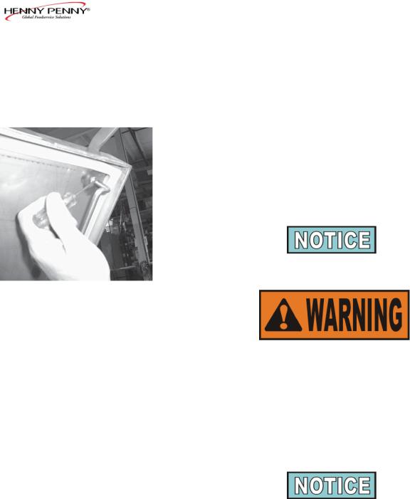
2-10. REVERSING THE LID |
The gray rubber gasket surrounding the inside of the lid is |
||
GASKET |
designed to be reversed. |
|
|
|
Because of heat expansion and the pressure used for the cook |
||
|
ing process, the gasket is constantly under extreme stress. |
||
|
Reversing the lid gasket will help to ensure that the fryer will |
||
|
not lose pressure through leakage. |
|
|
|
1. |
Put the lid in the upright position, as previously described. |
|
|
2. |
Using a thin blade screwdriver, pry out the gasket at the |
|
|
|
corners. Remove the gasket. |
|
|
|
Check the gasket for any tears or nicks. If the gasket is |
|
|
|
damaged, it needs to be replaced. |
|
|
|
Be sure the metal arm on the left side of the lid is in the |
|
|
|
vertical position holding the lid upright, or severe |
|
|
|
injuries could result. (See photo on page 2-7.) |
|
|
3. |
Clean the gasket and gasket seat with hot water. |
|
|
4. |
Rotate the gasket with the opposite side facing out. |
|
|
|
Install the four corners of the lid gasket. Smooth the gasket |
|
|
|
into place, working from the corners towards the middle of |
|
|
|
each |
side. |
2-8 |
1002 |
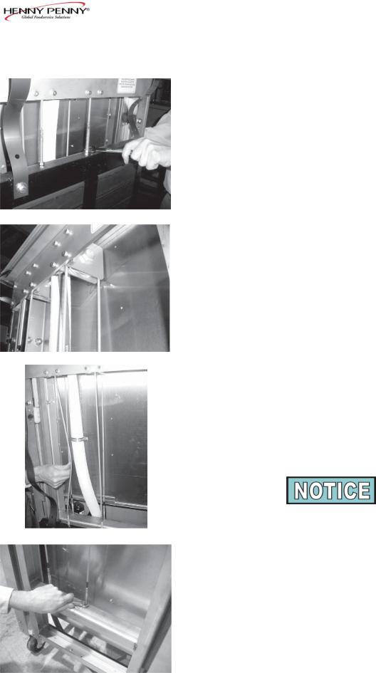
2-11. LID COUNTERWEIGHT The Lid Counterweight in the back of the fryer balances the CABLES weight of the lid system to allow easier opening and closing of
the lid. The weight has two cables attached to it, and weighs about 150 lbs. (67.5 Kg).
1.Using a 3/8” socket, remove the nuts securing the rear shroud of the fryer and remove the shroud.
2.Using Phillip’s-head screwdriver, remove screws securing the top cap and remove cap.
3.Raise the lid.
4.Unscrew the broken cable from the weight assembly and bracket attached to the fryer, and remove broken cable.
5.Screw a 5/16” nut on each end of the new cable.
6.Using a wrench, screw the new cable into the weight assembly until tight.
7.Using a 1/2” wrench, tighten nut (already threaded on the cable) against the weight assembly, securing the cable into
weight assembly.
8. Pull the cable over the pulley and down behind the weight assembly .
9.Insert the cable into the hole in bracket and screw a 5/16” nut onto end of the cable. Tighten cable, by screwing the cable through this nut until the weight assembly
becomes level.
The safety cable should now have slack in it with the weight assembly level.
10.Tighten the nut against the top of the bracket, securing the cable.
11.Replace top cap and rear shroud; repair is now complete.
507 |
2-9 |
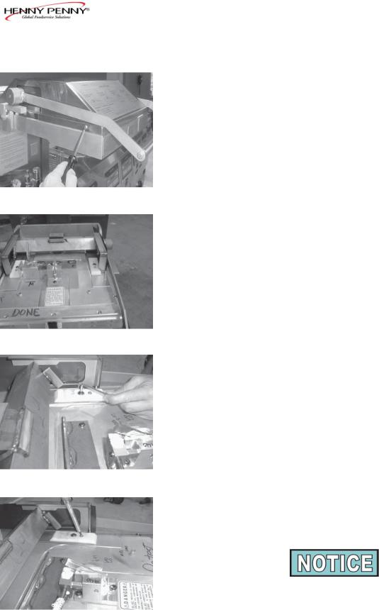
2-12. PRESSURE PAD |
The pressure pads are plastic strips that the lid cam presses |
|
|
against to seal the lid. |
|
|
1. |
Raise the lid. |
|
2. |
Remove the four screws securing the lid cover and remove |
|
|
cover. |
|
3. |
Push the lid cam back, off the pressure pads. |
4.Using an Allen wrench, remove the large bolt securing pad.
5.Using a Phillips head screw driver, remove the small screw securing the pad and remove the broken pad.
If the pressure pad is worn, but not broken, it can be reversed 180 degrees, and the other end of the pad used.
6.Install new pad in reverse order.
2-10 |
1002 |
2-13. LID ADJUSTMENT |
If steam leaks out from around the lid gasket, the pressure pads |
|
could be worn or broken. If the pressure pad is worn, but not |
|
broken, it can be reversed 180 degrees, and the other end of the |
|
pad used. See Section 2-12. |
|
If steam leaks, check for: |
• Pressure pad wear
• Cracked or worn gasket
• Gasket installed improperly
• Fryer operating above 12 psi (827 mbar)
Fryer should be operating at 12 psi (827 mbar), or serious burns could result.
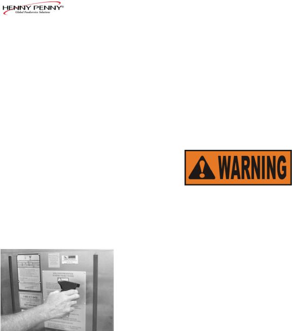
2-14. CLEAN THE NYLATRONS 1. Spray Henny Penny biodegradable, food safe, foaming degreaser (part no. 12226) on Nylatrons.
2.Raise lid up and down several times to spread degreaser.
3.Wipe Nylatrons to remove food soil, grease, and degreaser residue.
810 |
2-11 |
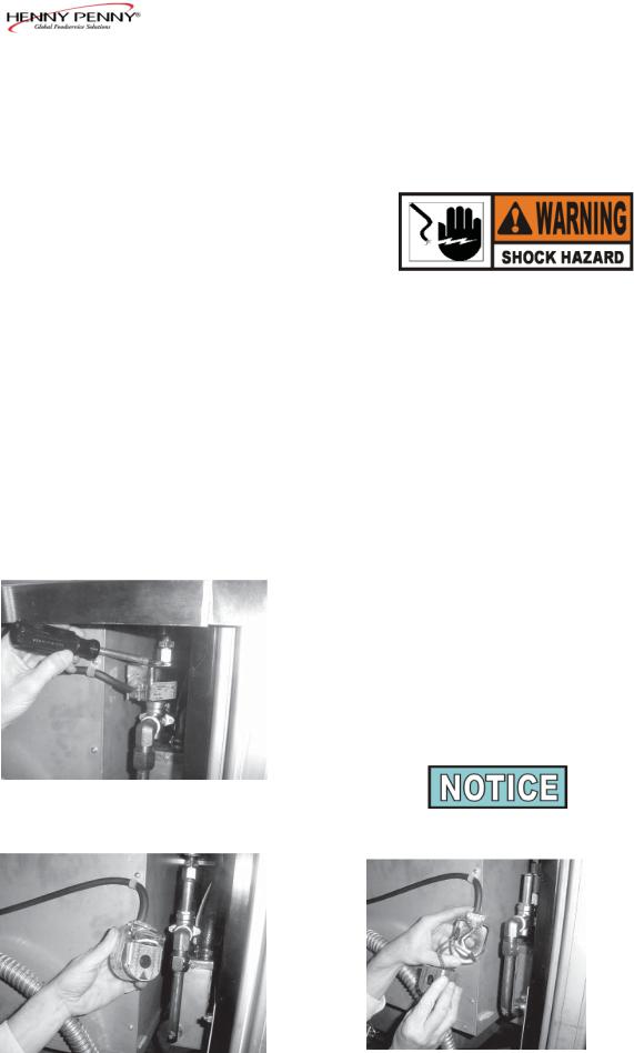
2-15. SOLENOID VALVE |
This is an electromechanical device that causes pressure to be |
|
held in the frypot. The solenoid valve closes at the beginning |
|
of the cook cycle and opens automatically at the end of the |
|
cook cycle. If this valve should become dirty, or the Tef on |
|
seat nicked, pressure will not build up. The gas fryer uses a |
|
120 volt, 60 Hz coil (208/240 volt, 50 Hertz internationally). |
To avoid electrical shock or property damage, move the power switch to OFF and disconnect main circuit breaker, or unplug cord at wall receptacle.
Coil Check Procedure
Remove the solenoid wires from the wire nuts which are found behind the control panel. Check across wires.
|
RESULTS |
208/240 Volt, 60 Hertz |
150 Ohms |
208/240 Volt, 50 Hertz |
230 Ohms |
120 Volt, 60 Hertz |
50 Ohms |
Replacement
1.Remove the right side panel.
2.Remove the Tru-Arc retaining clip on top of coil housing.
3.Remove the cover.
4.If only the coil is to be replaced, disconnect the two coil wires at the wire nuts in the coil housing. Remove the coil, insert new coil, and connect the wires at the wire nuts. Assemble in reverse order of disassembly.
The wires may be connected in any order.
2-12 |
807 |
 Loading...