


OFE-322
Henny Penny OFE-322, OFE-321, OFE-324, OFE-323, OFG-321 User Manual
...
Model OFE/OFG-321,322,323,324
SECTION 2. MAINTENANCE
2-1. INTRODUCTION
This section provides procedures for the checkout and replacement
of the various parts used within the fryer. Before replacing any
parts, refer to the Troubleshooting Section. It will aid you in
determining the cause of the malfunction.
2-2. MAINTENANCE HINTS
1. You may need to use a multimeter to check the electric
components.
2. When the manual refers to the circuit being closed, the
multimeter should read zero unless otherwise noted.
3. When the manual refers to the circuit being open, the
multimeter will read infinity.
2-3 HIGH TEMPERATURE
LIMIT CONTROL The high temperature limit control is a safety, manual reset control
(Gas Units)
that senses the temperature of the shortening. If the shortening
temperature exceeds 425°F (218°C), this switch will open
and shut off heat to the frypot. When the temperature of the
shortening drops to a safe operation limit, the control must be
manually reset by pressing the red reset button. The red reset
button is located under the control panel, in the front of the fryer.
This will allow heat to be supplied to the frypot once again.
Checkout Before replacing a high temperature limit control, check to see
that its circuit is closed.
The shortening temperature must be below 380°F
(193°C) to accurately perform this check.
Checkout:
1. Remove electrical power supplied to fryer.
To avoid electrical shock or property damage, move the
POWER switch to OFF and disconnect main circuit
breaker, or unplug cord at wall receptacle.
2. Remove the control panel.
203 2-1
Model OFE/OFG-321,322,323,324
2-3 HIGH TEMPERATURE
LIMIT CONTROL
(Continued)
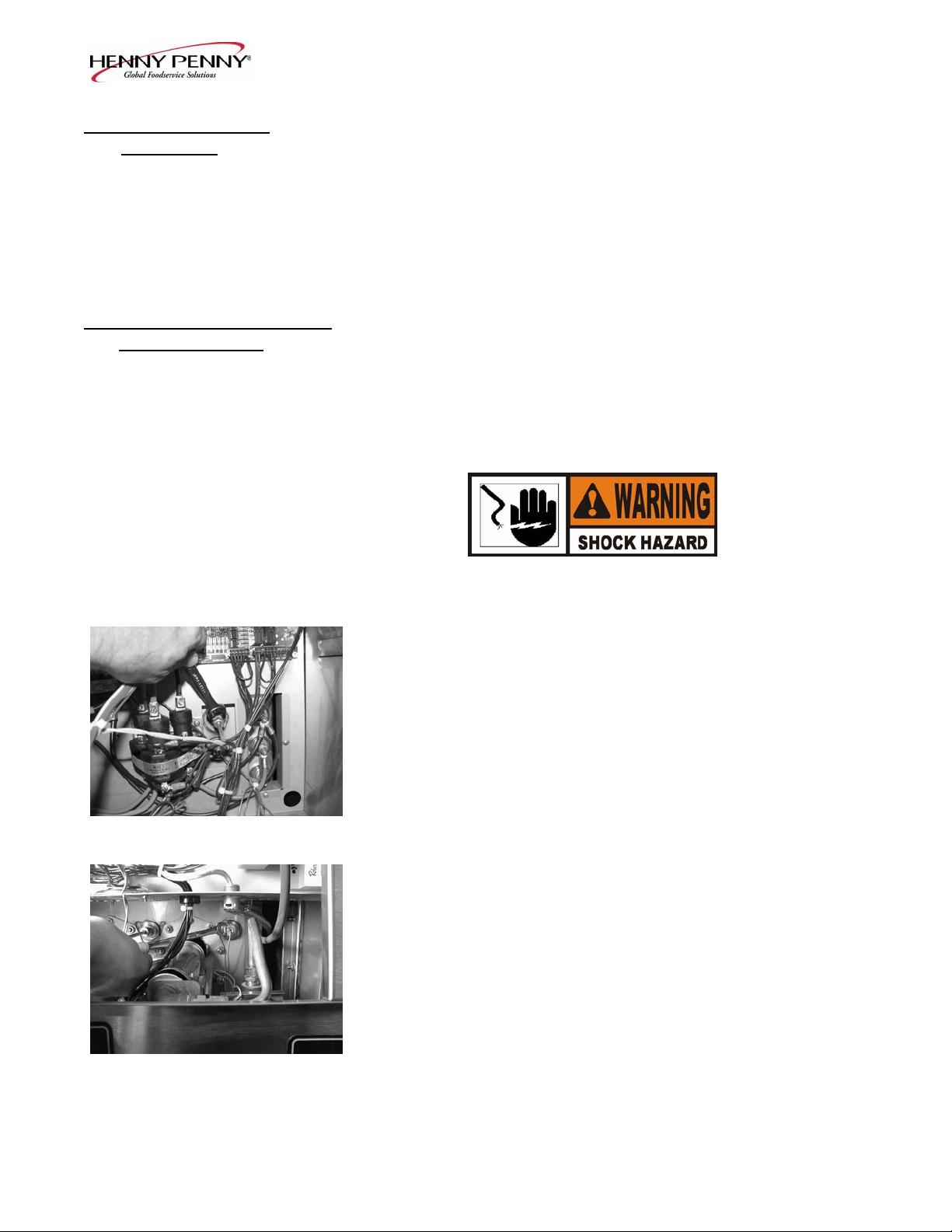
3. Remove the two nuts securing the high limit bracket to the unit
and pull the bracket from the unit.
4. Remove the two screws securing the high limit to the bracket,
and remove the high limit from the bracket.
5. Remove the two electrical wires from the high temperature
limit control.
6. Manually reset the control, then check for continuity between
the two terminals after resetting the control. If the circuit is
open, replace the control, then continue with this procedure.
(If the circuit is closed, the high limit is not defective. Re-
connect the two electrical wires.)
Replacement:
To avoid electrical shock or property damage, move the
POWER switch to OFF and disconnect main circuit
breaker, or unplug cord at wall receptacle.
1. If the tube is broken or cracked, the control will open, shutting
off electrical power to the heat circuit. The control cannot be
reset, and it will continuously click when pushed.
2. Drain the shortening from the frypot and discard. A substance
in the tube could contaminate the shortening.
3. Remove the control panel.
4. Loosen small inside screw nut on capillary tube.
2-2 203
Model OFE/OFG-321,322,323,324
2-3 HIGH TEMPERATURE
LIMIT CONTROL
(Continued)
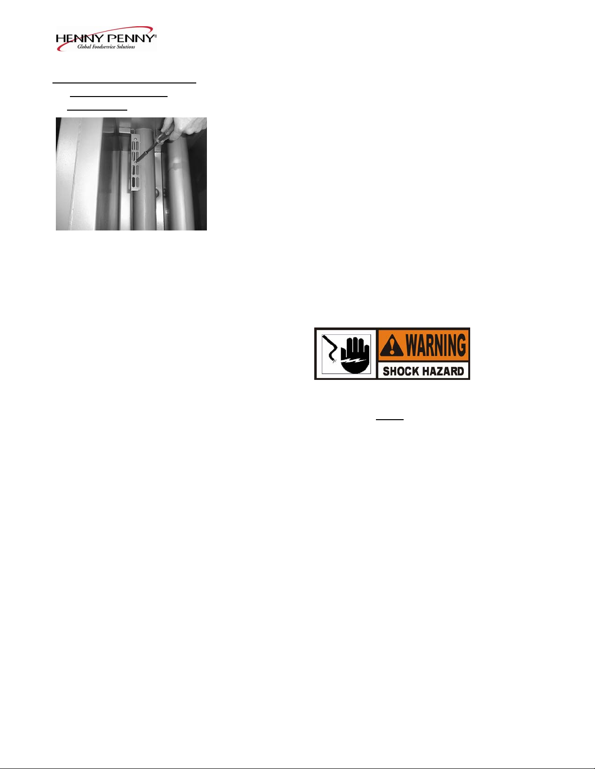
5. Remove the bracket from the heat tube covering the high limit
bulb.
6. Straighten the capillary tube behind the pot wall.
7. Pull the high limit bulb through the retainers on the heat tube.
8. Remove the larger outside nut that threads into the pot wall.
9. Remove the defective high limit from the control panel area.
10. Insert new high limit into bracket and replace wires.
11. Uncoil capillary line, starting at capillary tube, and insert
through frypot wall.
To avoid electrical shock or other injury, run the capillary
line under and away from all electrical power wires and
terminals. The tube must never
be in such a position where
it could accidentally touch the electrical power terminals.
12. Insert capillary line through brackets on heat tube, and then
pull back through pot wall until capillary bulb is secure in
brackets.
13. Pull excess capillary line from pot and tighten nut into
frypot wall.
14. With excess capillary line pulled out, tighten smaller nut.
15. Replace bracket on heat tube covering the high limit bulb.
16. Replace front panel.
17. Refill frypot with shortening.
203 2-3
Model OFE/OFG-321,322,323,324
2-4. COMPLETE CONTROL
PANEL REPLACEMENT
Should the control board become inoperative, follow these
instructions for replacing the board.
1. Remove electrical power supplied to the unit.
To avoid electrical shock or property damage, move the
POWER switch to OFF and disconnect main circuit
breaker, or unplug cord at wall receptacle.
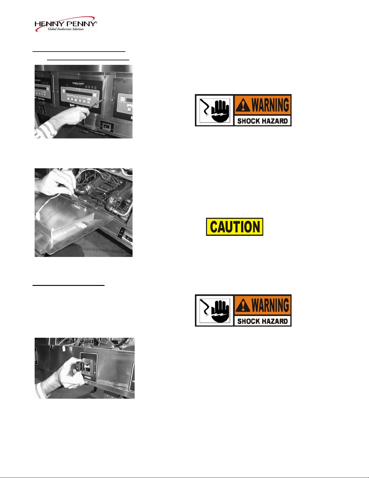
2. Remove the four screws securing the control panel and lift
out.
3. Unplug the wire connectors going to the control board.
4. Install new control panel in reverse order.
When plugging connectors onto new control panel, be sure
the connectors are inserted onto all of the pins, and that the
connectors are not forced onto the pins backwards. If not
connected properly, damage to the board could result.
2-5. POWER SWITCH 1. Remove electrical power supplied to fryer.
To avoid electrical shock or property damage, move the
POWER switch to OFF and disconnect main circuit
breaker, or unplug cord at wall receptacle.
2. Remove control panel.
3. Label and remove the wires from the switch. With test
instrument, check across the terminals of the switch with
the switch in the ON position, then in the OFF position.
With the switch in the ON position, the circuit should be
closed. With the switch in the OFF position, the circuit
should be open. If the switch checks defective, replace by
continuing with this procedure.
2-4 203
Model OFE/OFG-321,322,323,324
2-5. POWER SWITCH
(Continued)
4. With control panel removed, and the wires off the switch, push
in on tabs on the switch to remove from panel.
5. Replace with new switch, and reconnect wires to switch.
6. Replace the control panel.
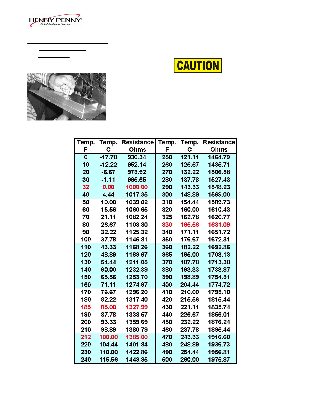
2-6. TEMPERATURE PROBE
The temperature probe relays the actual shortening temperature to
REPLACEMENT
the control board. If it becomes disabled, “E-6B” will show in the
display. Also, if the shortening temperature is out of calibration by
more than 10°F or C°, the temperature probe should be replaced.
An Ohm check can be performed also. See chart on page 2-7.
1. Remove electrical power supplied to the fryer.
To avoid electrical shock or property damage, move the
power switch to OFF and disconnect main circuit
Electric breaker, or unplug cord at wall receptacle.
2. Drain the shortening from the frypot.
3. Remove the control panel.
Gas
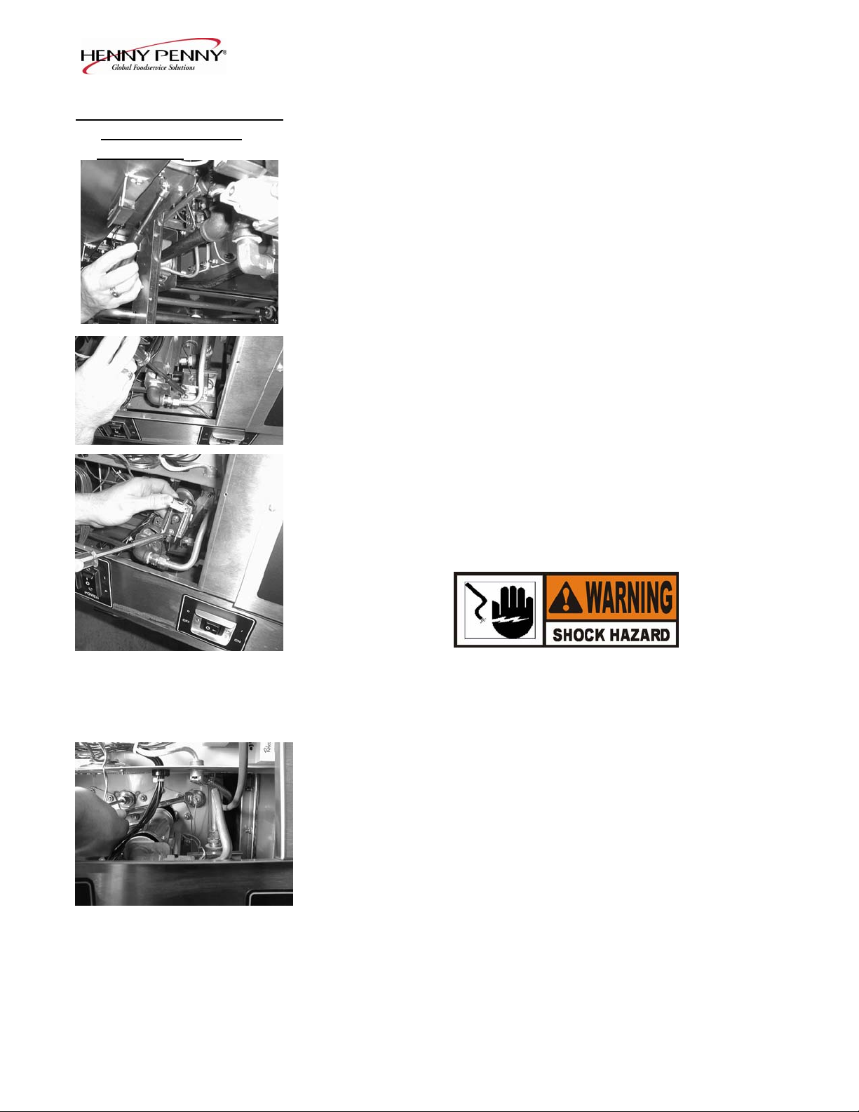
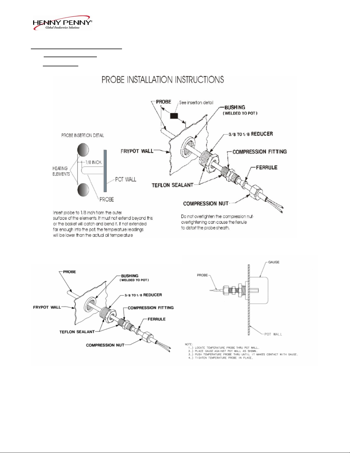
4. Using a 1/2" wrench, remove the nut on the compression
fitting.
5. Remove the temperature probe from the frypot.
6. Follow the appropriate instructions, on the following page,
depending upon the type of fryer, gas or electric.
606 2-5
Model OFE/OFG-321,322,323,324
2-6. TEMPERATURE PROBE
REPLACEMENT
(Continued)
ELECTRIC
GAS
2-6 606
Model OFE/OFG-321,322,323,324
2-6. TEMPERATURE PROBE 7. Tighten the compression nut hand tight and then a half turn
REPLACEMENT
with wrench.
(Continued)
Excess force will damage temperature probe.
8. Connect new temperature probe to PC board and replace
control panel.
9. Replace shortening.
10. Turn power on and check out fryer.
606 2-7

Model OFE/OFG-321,322,323,324
2-7. FLAME SENSOR
The flame sensor recognizes the pilot flame and allows gas to
(Gas Units)
continue to the pilot. The flame sensor must send a minimum of
two (2) micro amps to the ignition module. The pilot flame should
be split in two by the flame sensor, causing the flame sensor to be
bright red in color.
1. Remove electrical power supplied to the unit.
To avoid electrical shock or property damage, move the
POWER switch to OFF and disconnect main circuit
breaker, or unplug cord at wall receptacle..
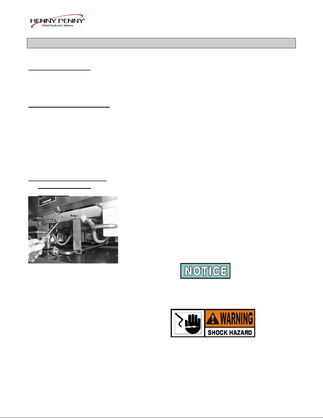
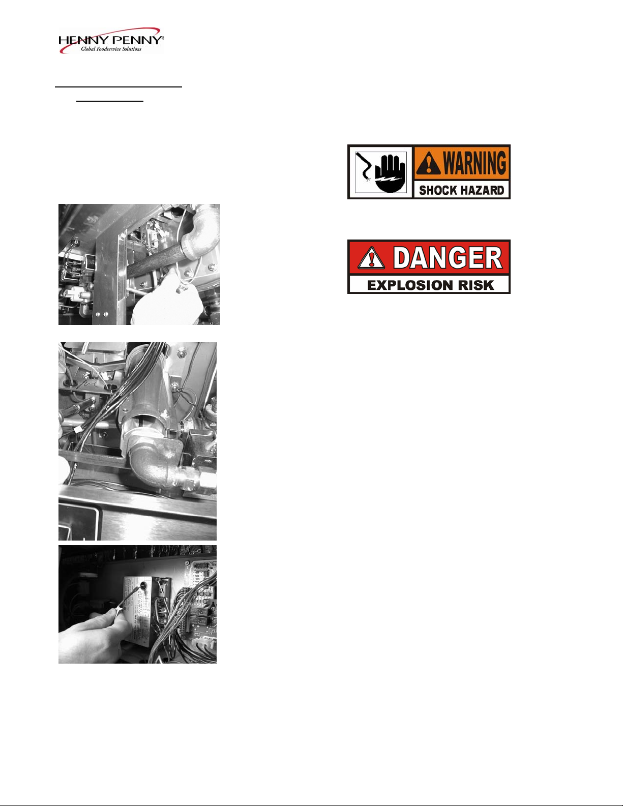
2. To access flame sensor, open the filter doors in the front of the
unit. Follow the small gauge yellow wire running to the sensor
behind the pilot assembly.
3. Disconnect the flame sense wire from the flame sensor.
4. Using a pair of needle nosed pliers, pull the flame sensor out
of the pilot assembly bracket.
5. Insert new flame sensor and reconnect flame sensor wire.
6. Turn power on and check fryer.
2-8 203
Model OFE/OFG-321,322,323,324
2-8. PILOT / IGNITOR The Henny Penny open fryer (gas) has electronic spark ignition
ASSEMBLY
that lights a standing pilot. The gap between the spark electrode
and the pilot hood should be set at 1/8 of an inch.
1. Remove electrical power supplied to the unit.
To avoid electrical shock or property damage, move the
POWER switch to OFF and disconnect main circuit
breaker, or unplug cord at wall receptacle.
TO AVOID PERSONAL INJURY OR PROPERTY
DAMAGE, BEFORE STARTING THIS
PROCEDURE, MOVE THE MAIN POWER SWITCH
TO THE OFF POSITION. DISCONNECT THE MAIN
CIRCUIT BREAKERS AT THE CIRCUIT BREAKER
BOX OR UNPLUG SERVICE CORD FROM WALL
RECEPTACLE. TURN OFF THE MAIN GAS
SUPPLY TO THE FRYER AND DISCONNECT AND
CAP THE MAIN SUPPLY LINE TO FRYER, OR
POSSIBLE EXPLOSION COULD RESULT.
2. Remove the control panel as discussed in Complete Control
Panel Replacement Section.
3. Disconnect the pilot gas line fitting at the pilot assembly with
a ½ inch wrench.
4. With a Phillips head screwdriver, remove the two screws
securing the pilot assembly to the mounting bracket.
5. Remove the flame sensor wire from the flame sensor.
6. Follow the wire from the spark ignitor back to the module, and
remove wire from module.
7. After removing assembly from unit, pull the flame sensor out
of the bracket as discussed in section 6-7. Insert flame sensor
into new pilot/ignitor assembly.
8. Reinstall the new pilot/ignitor assembly in reverse order. Be
extremely careful not to cross thread the pilot gas line fitting.
203 2-9
 Loading...