


SL-6157
Chime
Model SL-6157
Access
Door
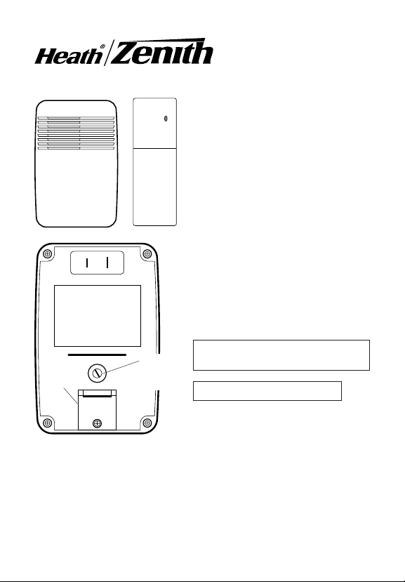
Figure 1
Chime
Volume
Control
Extender
Your chime extender includes (Style
of transmitter and chime may vary
from illustration):
• Plug-in doorbell chime
• Extension Transmitter
• Hardware pack
NOTE: You will need to purchase
four AAA batteries for the
transmitter.
Your Heath
lows you to add doorbell coverage to any
room in your house without the need to
run additional wires. The Chime Extender
"listens" for your existing doorbell to ring,
then transmits a radio frequency signal
to the plug-in chme unit in another part
of the house.
1. Set the chime volume on the back
2. Plug-in the doorbell chime.
To reduce the risk of electrical shock, this
equipment has a polarized plug (one
blade is wider than the other). This plug
will fit in a polarized outlet only one way.
If the plug does not fit fully in the outlet,
reverse the plug. If it still does not fit,
contact a qualified electrician to install the
proper outlet. Do not change the plug in
any way.
®
/Zenith Chime Extender al-
of the plug-in chime, if desired.
© 2003 DESA Specialty Products™ 595-5345-06
1 2 3 4 5 6 7 8
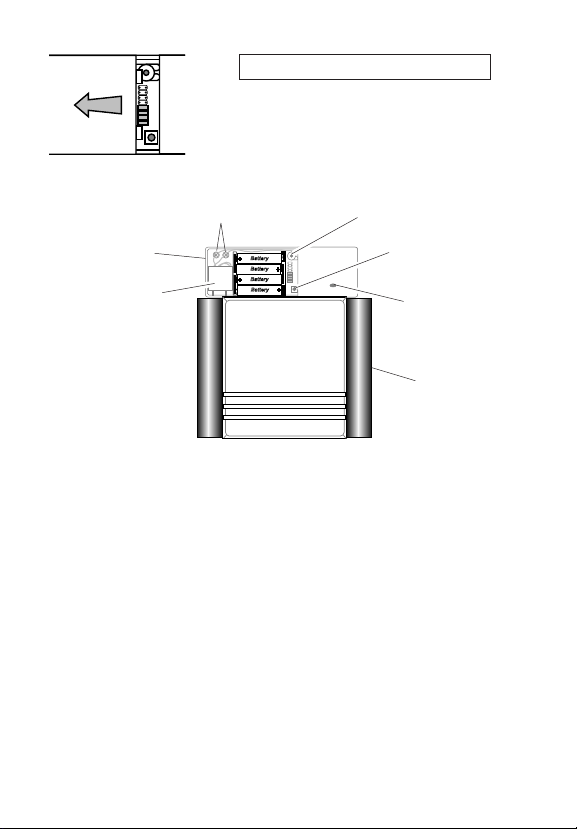
3. Install the Extension Transmitter.
1. Remove the battery cover from the Extension
Transmitter by pressing on the cover with your
thumb, then slide the cover off as shown Figure 2.
2. Install four AAA batteries (not provided). Make
Figure 2
Extension
Transmitter
Microphone
sure batteries are oriented properly (see page 5).
Microphone
Wire Terminals
Microphone Sensitivity
Adjustment
Test Button
Transmit
Light
Existing
Doorbell
Figure 3
3. Note: The transmitter can be oriented horizontally or vertically. Temporarily place the Extension Transmitter in the intended mounting position.
Press the Test Button. If the plug-in chime sounds, continue with step 4. If
the plug-in chime does not sound, go to the Troubleshooting section before continuing with step 4.
4. With the Extension Transmitter still in the intended location, activate the
existing door chime. If the plug-in chime sounds, proceed to step 7. If it
does not sound, try different positions for the transmitter, or increase the
microphone sensitivity (Figure 3) by turning the Microphone Sensitivity
Adjustment clockwise. In some instances, it may be necessary to take the
removable microphone out of the transmitter case, and mount it directly
on the existing chime case or inside the existing chime case on a resonating chamber (not on chime bars). Please note–the microphone wires can
be temporarily removed from the wire terminals (Figure 3) by loosening
the terminals with a phillips screwdriver if wire routing through small openings in the existing chime cover is desired. There is a slot on the transmitter cover for the wires if an external mounting is required. Double-sided
tape is provided to attach the microphone to your existing chime case.
-2-
595-5345-06
5. Adjust the Microphone Sensitivity so that it is at the least sensitive position to reliably activate the transmitter. If the sensitivity is set too high, it
may false trigger on common household noises.
6. When the system is working properly, carefully mark the desired location
of the Extension Transmitter, and go to step 7 for final installation.
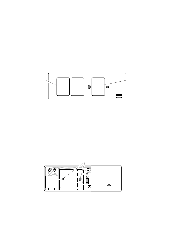
7a - Mount with Double Sided Tape
❐ Install the battery cover.
❐ Peel the protective backing from one side of two pieces of the double
sided tape, and apply the tape to the areas on the back of the transmitter
as shown in Figure 4.
Double
Sided Tape
Figure 4
Double
Sided Tape
❐ Remove the remaining protective backing. Carefully stick the transmitter
to the exact location marked in step 6.
7b - Mount with Screws & Hollow-Wall Fasteners
❐ Temporarily remove the batteries.
❐ Hold the transmitter in the desired location, and mark the two mounting holes.
❐ Set the transmitter aside. Drill two 7/32 inch mounting holes. Tap the hol-
low-wall fasteners into the two holes.
❐ Hold the transmitter in place, and secure with the two screws.
❐ Reinstall the batteries and the battery cover.
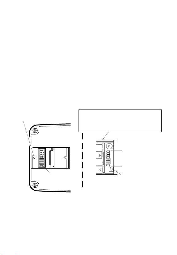
Mounting Holes
595-5345-06
Figure 5
-3-

Code and Tune Settings
Note: Most installations will not require you to change any of the jumpers on your doorbell.
WARNING: Disconnect chime unit from power source before opening
code access door. Close door and replace screw before reconnecting
to power.
The transmitter and chime communicate by using a code that can be changed
by removing and/or adding jumpers on both the transmitter and chime. The
code is factory set; however, there are 128 selectable codes that allow you
to expand your system and prevent outside interference. Another wireless
doorbell system or other wireless products may cause interference and the
system may not function properly. Follow the instructions below for setting a
new code.
1. Disconnect the power to the transmitter and chime.
2. Open the cases and locate the jumpers on both the transmitter and chime
(See illustration).
3. The transmitter and chime both have eight different jumper locations. The
jumper positions 1 through 7 are used for setting the code.
4. To change the code, add and/or remove jumpers as needed. There are
128 different combinations. It is recommended to only change one jumper
at a time and then check to see if system is functioning properly. Note:
Jumpers in positions 1 through 7 must be exactly the same for both the
transmitter and chime for this system to function.
Code Settings
-4-
595-5345-06
Your Heath
®
/Zenith wireless chime has different selectable tunes: Ding (one
Tune Settings
note), Ding-Dong (two note), or Westminster (eight note) (Available on selected Heath®/Zenith chimes). The factory setting is for the Ding-Dong tune
(or Westminster, when available). This tune can be changed by following the
instructions below.
• Ding (one note tune)
Transmitter: Add a jumper to location 8.
• Ding-Dong (two note tune)
Transmitter: Remove jumper from location 8.
Chime: Remove jumper from location 8.
• Westminster (Eight note tune) (Available on selected Heath®/Zenith
chimes)
Transmitter: Remove jumper from location 8.
Chime: Add a jumper to location 8.
Note: All models have both front and back door tune capabilities. You may
purchase any Heath
Remove screw to
open access door
®
/Zenith wireless push button for a second entrance.
Transmitter Battery Replacement
Install four alkaline AAA batteries. See
diagram inside push button for correct
battery orientation.
Back of
Chime
12345678
12345678
* Code Settings 1-7
Must Match Both
Transmitter and
Chime
Tune Setting
(Not used on
all models)
Inside
Transmitter
Tune Setting
Note: Some models might require the use of tweezers to remove and replace the jumpers.
595-5345-06
-5-

Troubleshooting
Chime does not sound:
• Red light on the transmitter does not light. Check polarity of batteries. Re-
place the transmitter batteries.
• Red light on the transmitter does light. Make sure the transmitter and the
chime channels are the same (see page 5). Make sure the plug-in chime
has power going to it.
Battery seems OK, but the chime does not work when installed:
• Do not mount the transmitter on metal or near metal studs. This reduces
the transmitter range. Use 1/4" to 1/2" (6 to 13 mm) wood shims to move
the transmitter off the metal surface.
• Attach the microphone directly to the existing chime case very near the
ringing part (but not on it) of the existing chime.
•Try locating chime closer to transmitter.
The range of the chime can vary with location, temperature, and battery condition.
Chime false triggers to loud noises:
The Extension Transmitter has special circuitry to reduce false triggers from
most common household noises. The transmitter is designed to optimize its
response to mid-frequency sound where most mechanical doorbells operate
and to minimize response to extremely low or high frequency sounds. Also,
the desired sound must be present continuously for at least 2 seconds. This
design reduces the response to door slams, vibration, normal music and
talking, etc. Loud continuous noises such as yelling children or very loud
music may cause false triggering. When operating in a location with unusually high ambient noise levels try the remedies below.
•Turn the sensitivity control counterclockwise to reduce sensitivity.
• Mount the microphone inside the existing chime as mentioned in step 4.
-6-
595-5345-06

Technical Service
If you experience a problem, follow this guide. You may also want to visit our Web
site at: www.desatech.com. If the problem persists, call* for assistance at 1-
800-858-8501, 7:30 AM to 4:30 PM CST (M-F). You may also write* to:
DESA Specialty Products™
P.O. Box 90004, Bowling Green, KY 42102-9004
ATTN: Technical Service Specialty Products
* If contacting Technical Service, please have the following information available: Model Number, Date of Purchase, and Place of Purchase.
No Service Parts Available for this Product
(Do Not Send Products)
Regulatory Information
This device (SL-6166-RX-A, SL-6157-A-TX) complies with Part 15 of the FCC
Rules and RSS-210 of Industry Canada. Operation is subject to the following
two conditions: (1) this device may not cause harmful interference, and (2)
this device must accept any interference received, including interference that
may cause undesired operation.
The user is cautioned that changes or modifications not expressly approved
by the party responsible for regulatory compliance could void the user’s authority to operate the equipment.
595-5345-06
-7-

This is a "Limited Warranty" which gives you specific legal rights. You may
FIVE YEAR LIMITED WARRANTY
also have other rights which vary from state to state or province to province.
For a period of five years from the date of purchase, any malfunction
caused by factory defective parts or workmanship will be corrected at no
charge to you. Batteries are not covered. To obtain a refund or a
replacement, return the product to the place of purchase.
Not Covered - Repair service, adjustment and calibration due to misuse,
abuse or negligence, light bulbs and other expendable items are not
covered by this warranty. Unauthorized service or modification of the
product or of any furnished component will void this warranty in its entirety.
This warranty does not include reimbursement for inconvenience, installation, setup time, loss of use, or unauthorized service.
This warranty covers only DESA Specialty Products™ assembled products and is not extended to other equipment and components that a
customer uses in conjunction with our products.
THIS WARRANTY IS EXPRESSLY IN LIEU OF ALL OTHER WARRANTIES, EXPRESS OR IMPLIED, INCLUDING ANY WARRANTY,
REPRESENTATION OR CONDITION OF MERCHANT ABILITY OR
THAT THE PRODUCTS ARE FIT FOR ANY PARTICULAR PURPOSE
OR USE, AND SPECIFICALLY IN LIEU OF ALL SPECIAL, INDIRECT,
INCIDENTAL, OR CONSEQUENTIAL DAMAGES.
REPAIR OR REPLACEMENT SHALL BE THE SOLE REMEDY OF THE
CUSTOMER AND THERE SHALL BE NO LIABILITY ON THE PART OF
DESA SPECIALTY PRODUCTS™ FOR ANY SPECIAL, INDIRECT, INCIDENTAL, OR CONSEQUENTIAL DAMAGES, INCLUDING BUT NOT
LIMITED TO ANY LOSS OF BUSINESS OR PROFITS, WHETHER OR
NOT FORESEEABLE. Some states or provinces do not allow the exclusion
or limitation of incidental or consequential damages, so the above limitation
or exclusion may not apply to you. Retain receipt for warranty claims.
DESA Specialty Products™ reserves the right to discontinue and to change
specifications at any time without notice without incurring any obligation to
incorporate new features in previously sold products.
-8-
595-5345-06
 Loading...