


High Pressure Sodium Dusk-
to-Dawn Security Light
Model SL-5660
Installation Instructions
READ ALL INSTRUCTIONS CAREFULLY BEFORE BEGINNING INSTALLATION.
NOTE: All wiring must be run in accordance with the National Electrical Code (Canadian Electrical Code in Canada) through conduit or another acceptable means. Contact a qualified electrician if there is any question as to the suitability of the system.
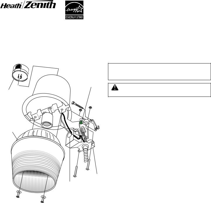
Photocontrol
Lens/Reflector
Assembly
Ground
Screw
Cover Plate
Fixture wires thru this hole
Lamp in Fixture Contains Mercury. Dispose According to Local, State, or Federal Laws.
 WARNING: Turn power off at the fuse or circuit breaker.
1.Select a location on a flat wall with structurally sound wood and from 10 to 25 feet (3 to 7.6 m) from the ground. The wood should be at least one inch (25 mm)thick to safely secure the fixture.
2.Using the mounting template as a guide, mark the 3 mounting holes. We suggest drilling 3/16" (4.8 mm) pilot holes for the lag screws.
3.Install the two bottom lag screws first. Screw in the lag screws so that there is about 3/8" (9.5 mm) of space under the head.
4.Place the fixture on these two screws and install the top lag screw. Tighten the top lag screw first, then tighten the remaining lag screws.
5.Secure your outdoor cable or flexible conduit to the cover plate with a fitting in accordance with the National Electrical Code.
6.Thread the black and white fixture wires through the hole in the cover plate as shown.
7.Connect the fixture wires to the service wires (black to black and white to white).
8.This fixture must be connected to ground. Secure the service ground wire under the head of the green ground screw.
9.Install the cover plate. Secure with the two screws and nuts provided.
10.Install the reflector/lens assembly. Secure with the two screws and washers provided.
11.Screw in the 70 watt H.P. Sodium type S62 lamp provided.
12.Loosen the screw in the center of the photocontrol socket two turns. Twist the socket so that the arrow points north. Note: There is a stop to prevent the socket from turning all the way around. If you have trouble turning the socket, try turning it the other direction. Retighten the screw in the center of the socket.
13.Align the photocontrol (it will only plug-in one way). Plug it in and twist clockwise until it stops.
To test operation during daylight, cover the photocontrol with a small box. Turn on the power. Not all photocontrols are alike. Some may have a time delay of a few minutes, others will turn on as soon as power is applied. The light will take up to ten minutes to reach full brightness. Uncover the photocontrol and your unit will operate automatically—on at dusk, off at dawn.
© 2007 HeathCo LLC |
598-1089-03 |

Ballast Assembly Replacement Instructions
Ballast assembly can be replaced without the cutting of any wires. Use of a qualified electrician is recommended.
 WARNING: Turn power off at the fuse or circuit breaker.
1.Remove bulb.
2.Loosen two screws holding plastic/aluminum reflector and remove reflector.
3.Remove two screws connecting ballast assembly to aluminum housing.
4.Remove tape from wire bundle. Be careful not to damage wires.
5.Label wires according to wiring diagram.
6.Remove wire nuts from wires. Retain wire nuts to connect replacement ballast assembly.
7.Remove screw holding ignitor to ballast assembly.
8.Remove two screws holding lamp socket to ballast assembly.
9.Dispose of used ballast assembly.
10.Connect the replacement ballast assembly following steps 1 through 8 in reverse order.
|
Red |
|
|
Photocell |
|
|
|
|
|
||
|
|
|
|
Socket |
|
Black |
Lamp |
|
WhiteWhite |
Black |
|
Socket |
Black |
||||
Red |
|
||||
|
|
|
Red |
White |
|
|
Blue |
Blue |
|
|
|
|
|
White |
|
||
|
|
|
|
Black |
|
|
Ballast |
|
|
|
|
|
|
|
Ignitor |
120V AC |
|
|
|
|
|
Input |
|
Aluminum
Housing
Ignitor Retention Screw
Ballast Assembly
Ignitor
Lamp Socket
Lock Washer
Ballast Retention Screw
Lamp Socket
Retention Screw
2 |
598-1089-03 |
Luz de Seguridad del Atardecer al
Amanecer con Sodio a Alta Presión
Modelo SL-5660
Indicaciones para su instalación
LEA TODAS LAS INDICACIONES CON CUIDADO ANTES DE COMENZAR LA INSTALACION.
NOTA: Todo el cableado debe realizarse de acuerdo con el Código Nacional Eléctrico (Código Eléctrico Canadiense en Canadá) usando tubería u otro medio aceptable. Contáctese con un electricista calificado si tiene alguna pregunta respecto a la adaptabilidad del sistema.
La lámpara en el dispositivo contiene mercurio. Deseche de acuerdo con las leyes locales, estatales o federales.
Tornillo de conexión a tierra
Fotocontrol
ADVERTENCIA: Apague la energía en el fusible o cortacircuitos.
|
1. |
Escoja un lugar sobre una pared plana y con una buena estructura |
|
|
|
de madera de 3 a 7,6 m (10 a 25 pies)del piso. La madera deber ser |
|
|
|
de por lo menos 25 mm (una pulgada) de espesor para que sostenga |
|
|
|
el aparato con seguridad. |
|
Conjunto del |
2. |
Usando la plantilla de montaje como guía, marque los tres agu- |
|
|
jeros de montaje. Le sugerimos que perfore agujeros pilotos de |
||
Reflector/Placa |
|
||
|
4,8 mm (3/16 pulg.) para los tirafondos. |
||
Translúcida |
|
||
|
3. |
Instale primero los dos tirafondos del fondo.Atornille los tirafondos |
|
|
|
de manera que haya un espacio de 9,5 mm (3/8 pulg.) debajo de la |
|
|
|
cabeza. |
|
|
4. |
Ponga el aparato sobre estos dos tornillos e instale el tirafondo |
|
|
|
de arriba. Ajuste primero el tirafondo de arriba y luego los tira- |
|
|
|
fondos restantes. |
|
|
5. |
Asegure el cable de fuera de casa o el conducto flexible a la |
|
|
|
placa cubertora con un accesorio de cableado de acuerdo con |
|
Placa |
|
el Código Eléctrico Nacional. |
|
6. |
Pase los cables negro y blanco del aparato por el agujero de la |
||
Cubertora |
|
placa cubertora, como se muestra. |
|
Cables del aparato |
|
||
7. |
Conecte los cables del aparato a los cables de servicio (negro |
||
por este agujero |
|||
|
a negro y blanco a blanco). |
||
|
|
||
|
8. |
Este aparato debe estar conectado a tierra. Asegure el cable de co- |
|
|
|
nexión a tierra de servicio debajo de la cabeza del tornillo verde de |
|
|
|
conexión a tierra. |
|
|
9. |
Instale la placa cubertora. Asegúrela con los dos tornillos y |
|
|
|
tuercas suplidos. |
|
|
10. Instale el conjunto del reflector/placa translúcida. Asegúrelo con |
||
|
|
los dos tornillos y arandelas suplidos. |
|
|
11. Atornille la lámpara suplida de 70 vatios de sodio a A.P. tipo |
||
|
|
S62. |
|
12.Afloje con dos giros el tornillo del centro del enchufe del fotocontrol. Gire el enchufe de tal forma que la flecha apunte hacia el norte. Nota: Existe un tope para evitar que el enchufe gire por completo. Si tiene problemas en girar el enchufe, trate de girarlo en la otra dirección. Ajuste de nuevo el tornillo del centro del enchufe.
13.Alinee el fotocontrol (se enchufa en sólo una dirección). Enchúfelo y gírelo hacia la derecha hasta que tope.
Para probar su funcionamiento durante el día, cubra el fotocontrol con una caja pequeña. Prenda la electricidad. No todos los fotocontroles son iguales. Algunos pueden tener un retardo de tiempo de unos pocos minutos, otros pueden prenderse tan pronto como se aplique la electricidad. La luz tomará unos diez minutos hasta llegar a su máxima claridad. Descubra el fotocontrol y la unidad funcionará automáticamente --prendida al atardecer, apagada al amanecer.
© 2007 HeathCo LLC |
3 |
598-1089-03 S |
|
|
598-1089-03 |
 Loading...