


INSTALLATION
MANUAL
VMH 09/12/18/27/36
Version C
InverterFlex
Ductless Mini-Split Heat Pump
Heat Controller, Inc. • 1900 Wellworth Ave. • Jackson, MI 49203 • (517)787-2100 • www.heatcontroller.com
VMH InverterFlex Mini-Split |
INSTALLATION MANUAL |
Heat Controller, Inc. |
Table of Contents |
|
|
Safety Precautions |
|
|
Warnings and Cautions............................................................................ |
|
2 |
Installation Instructions |
|
|
Selecting an installation location.............................................................. |
|
3 |
Accessories.............................................................................................. |
|
4 |
System installation.................................................................................... |
|
5 |
Indoor unit installation............................................................................... |
|
6 |
Outdoor unit installation............................................................................ |
|
9 |
Refrigerant Pipe Connection |
|
|
Refrigerant pipe connection.................................................................... |
|
10 |
Electrical Work |
|
|
Electrical Work........................................................................................ |
|
12 |
Air Purging |
|
|
Air purging with vacuum pump............................................................... |
|
14 |
Safety and refrigerant leak check........................................................... |
|
16 |
Testing the System |
|
|
Test Run................................................................................................. |
|
17 |
!Caution
•Contact an authorized service technician for repair or maintenance of this unit.
•Contact an authorized installer for installation of this unit.
•Installation work must be performed in accordance with local and national electrical codes and standards by authorized personnel only.
1
Heat Controller, Inc. |
INSTALLATION MANUAL |
VMH InverterFlex Mini-Split |
•Read the follow SAFETY PRECAUTIONS carefully before installation.
•Electrical work must be performed by a licensed electrician. Be sure to use the correct rating of the power cord and main circuit for the model to be installed.
•Incorrect installation due to ignoring the instruction will cause harm or damage.
nThe seriousness is classified by the following indications.
!WARNING! This symbol indicates the possibility of death or serious injury.
!CAUTION! This symbol indicates the possibility of injury or damage to property.
The items to be followed are classified by the symbols:
This symbol denotes item that is PROHIBITED from doing.
!WARNING!
1)Do not install without an authorized servicer/installer.
2)Install according to this installation instruction. If installation is defective, it can cause water leakage, or electrical shock/fire.
3)Use the supplied accessories and specified parts for installation.
4)Install the indoor unit on a wall strong enough to hold the unit’s weight. Install the outdoor unit on a raised concrete pad or blocks to provide a solid, level foundation. In a location with high winds, anchor the unit and provide an air baffle. In snowy areas (for heat pump models), install the outdoor unit on a raised platform so that it is higher than drifting snow. Provide snow vents.
5)For electrical work, follow local and national electric codes and these installation instructions. An independent circuit and single outlet must be used. If electrical circuit capacity is not enough or defects are found in electrical work, it will cause electrical shock or fire.
6)Use the specified cable and connect tightly and clamp the cable so that no external force will stress the terminal. Loose wiring may cause overheating at the connection points and a possible fire hazard.
7)Wiring routing must be properly arranged so that control board cover is fixed properly. If control board cover is not fixed perfectly, it will cause overheating at connection point of terminal, fire or electrical shock.
8)When charging the unit, take care not to let air/substances other than the specified refrigerant go into refrigeration cycle. Otherwise, it will cause lower capacity, abnormal high pressure in the refrigeration cycle, explosion and injury.
9)Do not modify the length of the power supply cord or use an extension cord, and do not share the single outlet with other electrical appliances. Otherwise, it will cause fire or electrical shock.
!CAUTION!
1)This equipment must be grounded and installed with a ground leakage current breaker. It may cause electrical shock if grounding work doesn’t comply with local/national electric codes.
2)Do not install the unit at place where leakage of flammable gas may occur. If gas leaks and accumulates near the unit, it may cause fire.
3)Carry out drainage piping as mentioned in installation instructions. If not done correctly, water may enter the room and damage personal belongings.
2
VMH InverterFlex Mini-Split |
INSTALLATION MANUAL |
Heat Controller, Inc. |
1. Wall-mounted type
Selecting installation place
Read completely, then follow step by step.
Indoor unit
•Do not expose the indoor unit to heat or steam.
•Select a place where there are no obstacles in front or around the unit.
•Make sure that condensation drainage can be conveniently routed away.
•Do not install near a doorway.
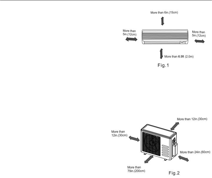
•Ensure that the space on the left and right of the unit is more than 5in.(12cm).
•Use a stud finder to locate studs to prevent unnecessary damage to the wall.
•The indoor unit should be installed on the wall at a height of 6.5ft.(2m) or more from the floor.
•The indoor unit should be installed allowing a minimum clearance of 6in.(15cm) from the ceiling.
•Any variations in pipe length may require adjustment to refrigerant charge.
•Do not expose unit to direct sunlight. The sun will fade the plastic cabinet and affect its appearance.
Outdoor unit
•If an awning is built over the outdoor unit to prevent direct sunlight or rain exposure, make sure that heat radiation from the condenser is not restricted.
•Ensure that the clearance around the back of the unit is more than 12in.(30cm) and left side is more than 12in.(30cm). The front of the unit should have more than 79in.(200cm) of clearance and the connection side (right side) should have more than 24in.(60cm)of clearance.
•Do not place animals and plants in the path of the air inlet or outlet.
•Take the air conditioner weight into account and select a place where noise and vibration will not be an issue.
•Select a place so that the warm air and noise from the air conditioner do not disturb neighbors.
Rooftop installation
•If the outdoor unit is installed on a roof structure, be sure to level the unit.
•Ensure the roof structure and anchoring method are adequate for the unit location.
•Consult local codes regarding rooftop mounting.
•If the outdoor unit is installed on roof structures or external walls, this may result in excessive noise and vibration, and may also be considered a non-serviceable installation.
3
Heat Controller, Inc. |
|
INSTALLATION MANUAL |
|
|
|
|
|
VMH InverterFlex Mini-Split |
|||||||||||
|
|
|
|
|
|
|
|
|
|
|
|
|
|
|
|
|
|
|
|
Tools needed for installation: |
|
|
|
|
|
|
|
|
|
|
|
|
|
|
|
|
|||
|
Level gauge |
|
|
|
|
|
|
|
|
|
|
|
|
|
|
|
|
|
|
|
Level gauge |
|
|
|
|
|
|
|
Vacuum pump |
||||||||||
|
Screwdriver |
|
|
|
|
|
|
|
|||||||||||
|
Screwdriver |
|
|
|
|
|
|
|
Gauge manifold |
||||||||||
|
ElectricElectricdrill,drill,Holelecore drilli l(o .25in6in..(65mm)) |
|
|
|
|||||||||||||||
|
tool |
|
|
|
|
|
|
|
Users manual |
||||||||||
|
Flaringtool set |
|
|
|
|
|
|
|
Thermometer |
||||||||||
|
Specified torque wrenches: 1.8kgf.m, 4.2kgf.m, |
||||||||||||||||||
|
Torque wrench |
|
|
|
|
|
|
|
Multimeter |
||||||||||
|
5.5kgf.m, 6.6kgf.m(different depending on model No.) |
||||||||||||||||||
|
Spanner (half union) |
|
|
|
|
|
|
Pipe cutter |
|||||||||||
|
Spanner (half union) |
|
|
|
|
|
|
||||||||||||
|
wrench (1.5in. |
|
|
|
|
|
|
Measuring tape |
|||||||||||
|
Hexagonal wrench (1.5in.(4mm)) |
|
|
|
|||||||||||||||
- |
|
|
|
|
|
|
|
|
|
|
|
|
|
|
|
|
|
|
|
|
Gas-leakdetector |
|
|
|
|
|
|
|
|
|
|
|
|
|
|
|
|
||
Accessories |
|
|
|
|
|
|
|
|
|
|
|
|
|
|
|
|
|||
|
|
|
|
|
|
|
|
|
|
|
|
|
|
|
|
||||
|
Number |
|
Name of Accessories |
|
|
|
|
|
|
|
|
Q Qty/unitt o e unit |
|
||||||
|
1 |
|
Installation Plate |
|
|
|
|
|
|
|
1 |
|
|
|
|
||||
|
2 |
|
Plastic Expansion Sheath |
|
|
|
|
|
|
|
8 |
|
|
|
|
||||
|
3 |
|
Self-tapping Screw A ST3.9X25 |
|
|
|
|
8 |
|
|
|
|
|||||||
|
4 |
|
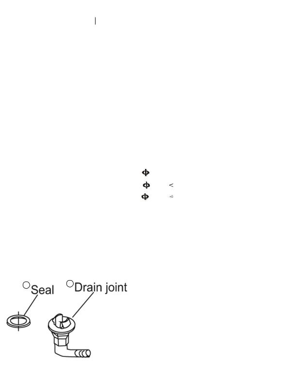
Seal (See Page 8 for details) |
|
|
|
|
1 |
|
|
|
|
|||||||
|
5 |
|
Drain Joint (See page 8 for details) |
|
|
|
|
1 |
|
|
|
|
|||||||
|
|
|
|
Liquid side |
|
|
|
|
|
|
|
|
|
|
Parts you must |
|
|
|
|
|
|
|
|
|
|
|
1/4" (6.35mm) |
|
|
|
|
|
|
|
|
|
|||
|
6 |
|
Connecting |
|
|
6.35 |
|
|
|
|
|
purchase |
|
||||||
|
|
|
|
|
|
|
|
|
|
|
|
||||||||
|
|
|
|
|
|
|
|
|
|
|
|
||||||||
|
|
pipe |
|
|
|
|
|
|
|
|
|
(The minimum pipe |
|
||||||
|
|
Gas side |
|
|
|
|
3/8"9.53(9.(53mm)12000Btu/h(<12,000 Btu/hmodel)model) |
|
|
|
|||||||||
|
|
|
Assembly |
|
|
|
|
|
|
|
|
|
wall-thickness |
|
|||||
|
|
|
|
|
|
|
|
|
|
|
|
|
|
||||||
|
|
|
|
|
|
|
|||||||||||||
|
|
|
|
|
1/2" (12(.7mm)12000Btu/h(≥12,000 Btu/hmodel)model) |
|
|
|
|||||||||||
|
|
|
|
|
|
|
12.7 |
|
|
|
|
|
of 0.7mm is required. ) |
|
|||||
|
7 |
|
Remote controller |
|
|
|
|
|
|
|
1 |
|
|
|
|
||||
|
|
|
|
|
|
|
|
|
|
|
|
|
|
|
|
||||
|
8 |
|
Self-tapping Screw B ST2.9X10 |
|
|
|
|
2 |
|
|
|
|
|||||||
|
9 |
|
Remote controller holder |
|
|
|
|
|
|
|
1 |
|
|
|
|
||||
|
|
|
|
|
|
|
|
|
|
|
|
|
|
|
|
|
|
|
|
Note: Except the above parts provided, the other parts needed during installation you must purchase.
4 5
4

VMH InverterFlex Mini-Split |
INSTALLATION MANUAL |
Heat Controller, Inc. |
|
|
|
Single-Dual Zone
Single-Tri Zone
Single-Quad Zone
CAUTION
•Use a stud finder to locate studs to prevent unnecessary damage to the wall.
•A minimum pipe run of 9.8 ft (3m) is required to minimize vibration & excessive noise.
•Two of the “A,” “B” and “C” air flow directions should be free from obstructions for the outdoor unit.
5
 Loading...