


INSTALLATION, OPERATION & MAINTENANCE MANUAL
Residential Packaged
Geothermal Heat Pump
HEV/H Series
2 to 5 Tons
Heat Controller, Inc. • 1900 Wellworth Ave. • Jackson, MI 49203 • (517)787-2100 • www.heatcontroller.com

Installation, Operation & Maintenance |
HEV/H SERIES |
Heat Controller, Inc. |
|
TABLE OF CONTENTS |
|
Model Nomenclature ............................................................................................ |
|
3 |
Safety Instructions................................................................................................ |
|
4 |
Pre-Installation...................................................................................................... |
|
5 |
Physical Data........................................................................................................ |
|
6 |
Vertical Unit Dimensions.................................................................................... |
|
7-8 |
Vertical Installation................................................................................................ |
|
9 |
Water Connection Installation............................................................................. |
14 |
|
Ground-Loop Heat Pump Applications .......................................................... |
15-16 |
|
Ground-Water Heat Pump Applications.............................................................. |
17 |
|
Water Quality Standards .................................................................................... |
|
18 |
Hot Water Generator ..................................................................................... |
|
19-21 |
Electrical Data ............................................................................................... |
|
22-26 |
Blower Performance Data ............................................................................. |
|
27-28 |
Wiring Diagrams................................................................................................. |
|
29 |
DXM2 Controls .............................................................................................. |
|
30-31 |
Unit Start-Up and Operating Conditions........................................................ |
32-38 |
|
Preventive Maintenance..................................................................................... |
|
39 |
Troubleshooting............................................................................................. |
|
40-44 |
2
Heat Controller, Inc. |
HEV/H SERIES |
Installation, Operation & Maintenance |
|
|
|
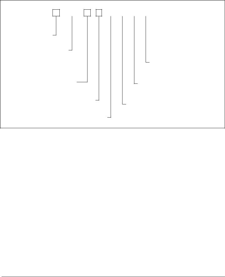
UNIT NOMENCLATURE
|
HeatController |
|
|
1 |
2 |
|
3 |
4 |
5 |
6 |
7 |
8 |
|
HEV |
|
|
|
||||||||
|
HEH |
|
|
|
|
|
|
|
|
|
|
|
|
|
|
HE |
|
H |
0 3 6 |
B |
1 |
||||
|
MODEL TYPE |
|
|
|||||||||
|
|
|
|
|
|
|
|
|
|
|
||
|
|
|
|
|
|
|
|
|
|
|
||
|
HE = HEAT CONTROLLER RESIDENTIAL 410A |
|
|
|
|
|
|
|||||
CONFIGURATION
H = HORIZONTAL
V = VERTICAL
UNIT SIZE
024
030
036
042
048
060
REVISION LEVEL
A = Current Revision
B = Current Revision
for Sizes 024, 036, 060
VOLTAGE
1 = 208-230/60/1
CONTROLS
D = DXM 2
9 |
10 |
11 |
12 |
13 |
14 |
|
|
|||||||
D |
|
0 |
|
0 |
|
A |
|
L |
|
B |
|
|||
|
|
|
|
|
|
|
|
|
|
|
|
|
|
SUPPLYAIR OPTIONS |
|
|
|
|
|
|
|
|
|
|
|
|
|
|
|
|
|
|
|
|
|
|
|
|
|
|
|
|
|
B = BACK DISCHARGE, HORIZONTAL ONLY |
|
|
|
|
|
|
|
|
|
|
|
|
|
|
T = TOP DISCHARGE, VERTICAL ONLY |
|
|
|
|
|
|
|
|
|
|
|
|
|
|
S = STRAIGHT DISCHARGE, HORIZONTAL ONLY |
|
|
|
|
|
|
|
|
|
|
RETURN AIR OPTIONS |
||||
|
|
|
|
|
|
|
|
|
|
|||||
|
|
|
|
|
|
|
|
|
|
L = LEFT RETURN w/ 1” Merv 8 Pleated Filter and Frame |
||||
|
|
|
|
|
|
|
|
|
|
R = RIGHT RETURN w/ 1” Merv 8 Pleated Filter and Frame |
||||
HEAT EXCHANGER OPTIONS
A = Copper Water Coil w/Tin Plated Air Coil
J = Cupro-Nickel Water Coil w/Tin Plated Air Coil
WATER CIRCUIT OPTIONS
0 = NONE
1 = HWG w/ INTERNAL PUMP
CABINET INSULATION
0 = RESIDENTIAL
DENTIAL CLASS UNITS COME STANDARD w/75 VA TRANSFORMER NLESS STEEL DRAIN PAN, LOOP PUMP, HWG CONNECTIONS, MOTOR, AND TWO STAGE SCROLL COMPRESSORS.
S ARE PAINTED POLAR ICE.
3
Installation, Operation & Maintenance |
HEV/H SERIES |
Heat Controller, Inc. |
|
|
|
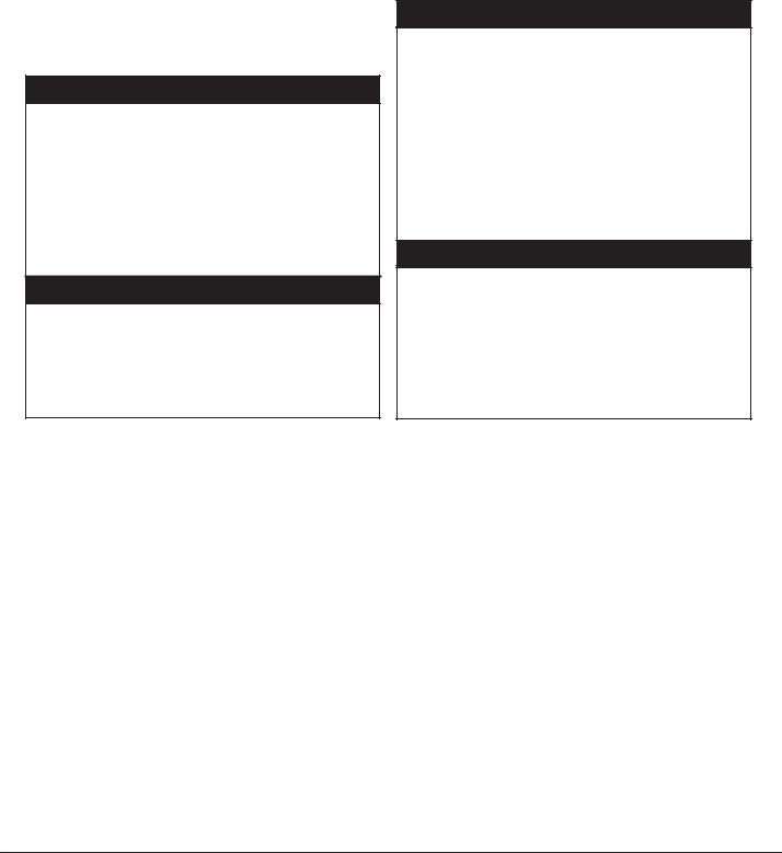
Safety
Warnings, cautions and notices appear throughout this manual. Read these items carefully before attempting any installation, service or troubleshooting of the equipment.
DANGER: Indicates an immediate hazardous situation, which if not avoided will result in death or serious injury. DANGER labels on unit access panels must be observed.
WARNING: Indicates a potentially hazardous situation, which if not avoided could result in death or serious injury.
ѥ WARNING! ѥ
WARNING! Verify refrigerant type before proceeding. Units are shipped withR--410A22 refrigerant.
ѥ WARNING! ѥ
WARNING! To avoid the release of refrigerant into the atmosphere, the refrigerant circuit of this unit must be serviced only by technicians who meet local, state, and federal proficiency requirements.
CAUTION: Indicates a potentially hazardous situation or an unsafe practice, which if not avoided could result in minor or moderate injury or product or property damage.
NOTICE: Notification of installation, operation or maintenance information, which is important, but which is not hazard-related.
ѥ WARNING! ѥ
WARNING! All refrigerant discharged from this unit must be recovered WITHOUT
EXCEPTION. Technicians must follow industry accepted guidelines and all local, state, and federal statutes for the recovery and disposal of refrigerants. If a compressor is removed from this unit, refrigerant circuit oil will remain in the compressor. To avoid leakage of compressor oil, refrigerant lines of the compressor must be sealed after it is removed.
ѥ CAUTION! ѥ
CAUTION! To avoid equipment damage, DO NOT use these units as a source of heating or cooling during the construction process. The mechanical components and filters will quickly become clogged with construction dirt and debris, which may cause system damage.
4
Heat Controller, Inc. |
HEV/H SERIES |
Installation, Operation & Maintenance |
|
|
|
GENERAL INFORMATION
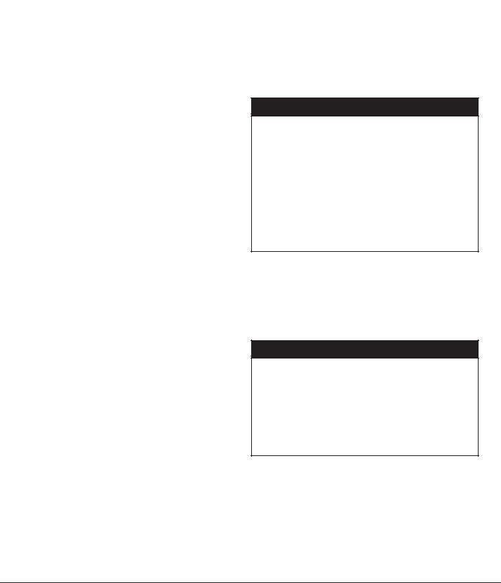
Inspection
Upon receipt of the equipment, carefully check the shipment against the bill of lading. Make sure all units have been received. Inspect the packaging of each unit, and inspect each unit for damage. Insure that the carrier makes proper notation of any shortages or damage on all copies of the freight bill and completes a common carrier inspection report. Concealed damage not discovered during unloading must be reported to the carrier within 15 days of receipt of shipment. If not filed within 15 days, the freight company can deny the claim without recourse. Note: It is the responsibility of the purchaser to file all necessary claims with the carrier. Notify Heat Controller of all damage within fifteen (15) days of shipment.
Storage
Equipment should be stored in its original packaging in a clean, dry area. Store units in an upright position at all times. Stack units a maximum of 3 units high.
Unit Protection
Cover units on the job site with either the original packaging or an equivalent protective covering. Cap the open ends
of pipes stored on the job site. In areas where painting, plastering, and/or spraying has not been completed, all due precautions must be taken to avoid physical damage to the units and contamination by foreign material. Physical
damage and contamination may prevent proper start-up and may result in costly equipment clean-up.
Examine all pipes, fittings, and valves before installing any of the system components. Remove any dirt or debris found in or on these components.
Pre-Installation
IInstallation,Operation,andMaintenanceinstructions areinstructionsprovided arewithprovidedeach unitwith. Horizontaleach unitequipment. Verticalisunit designedconfigurationsfor installationare typicallyaboveinstalledfalse ceilinga mechanicalor in ceiling plenumroom. The. Otherinstallationunit c figurationssite chosenareshouldtypicallyincludeinstalled
inadequatemechanical room. The installation site chosen ervice clearance around the unit. Before
should include adequate service clearance around the unit start-up, read all manuals and become familiar
unit. Before unit start-up, read all manuals and become with the unit and its operation. Thoroughly check the familiar with the unit and its operation. Thoroughly check system before operation.
the system before operation.
Prepare units for installation as follows:
1.Compare the electrical data on the unit nameplate with ordering and shipping information to verify that the correct unit has been shipped.
2.Keep the cabinet covered with the original packaging until installation is complete and all plastering, painting, etc. is finished.
3.Verify refrigerant tubing is free of kinks or dents and that it does not touch other unit components.
4.Inspect all electrical connections. Connections must be clean and tight at the terminals.
5.Remove any blower support packaging.
6.Loosen compressor bolts on units equipped with compressor spring vibration isolation until the
compressor rides freely on the springs. Remove shipping restraints.
77. . REMOVE COMPRESSOR SUPPORT PLATE 1/4”
8. Some airflow patterns are field convertible (horizontal
SHIPPING BOLTS (2 on each side) TO MAXIMIZE units only). Locate the airflow conversion section of
VIBRATION AND SOUND ATTENUATION. this IOM.
88.. Some airflow patterns are field convertible (horizontal 9 Locate and verify any hangers, or other accessory
units only). Locate the airflow conversion section of kits located in the compressor section or blower
this IOM. section.
9.Locate and verify any hangers, or other accessory kits located in the compressor section or blower section.
ѥ CAUTION! ѥ
CAUTION! DO NOT store or install units in corrosiveѥenvironmentsCAUTION!or in locationsѥ
subject to temperature or humidity extremes CAUTION! DO NOT store or install units
(e.g., attics, garages, rooftops, etc.).
in corrosive environments or in locations
Corrosive conditions and high temperature subject to temperature or humidity extremes
or humidity can significantly reduce (e.g., attics, garages, rooftops, etc.).
performance, reliability, and service life. Corrosive conditions and high temperature
Always move units in an upright position. or humidity can significantly reduce
Tilting units on their sides may cause performance, reliability, and service life.
equipment damage.
Always move units in an upright position.
Tilting units on their sides may cause
equipment damage.
NOTICE! Failure to remove shipping brackets from spring-mounted compressors will cause
excessive noise, and could cause component NOTICE! Failure to remove shipping brackets
failure due to added vibration.
from spring-mounted compressors will cause excessive noise, and could cause component
failure due to added vibration.
ѥ CAUTION! ѥ
CAUTION! CUT HAZARD - Failure to follow this cautionѥmayCAUTION!result in personalѥinjury.
Sheet metal parts may have sharp edges
CAUTION! CUT HAZARD - Failure to follow
or burrs. Use care and wear appropriate this caution may result in personal injury.
protective clothing, safety glasses and Sheet metal parts may have sharp edges
gloves when handling parts and servicing or burrs. Use care and wear appropriate
heat pumps.
protective clothing, safety glasses and
gloves when handling parts and servicing heat pumps.
5

Installation, Operation & Maintenance |
HEV/H SERIES |
|
|
Heat Controller, Inc. |
|||
|
|
|
|
|
|
|
|
|
|
PHYSICAL DATA |
|
|
|
||
|
|
|
|
|
|
|
|
Model |
024 |
030 |
036 |
042 |
048 |
060 |
|
|
|
|
|
|
|
|
|
Compressor (1 Each) |
|
Copeland UltraTech Two-Stage Scroll |
|
|
|||
Factory Charge HFC-410a, oz |
51 |
48 |
54 |
70 |
80 |
84 |
|
ECM Fan Motor & Blower |
|
|
|
|
|
|
|
|
|
|
|
|
|
|
|
Fan Motor, hp [W] |
1/2 [373] |
1/2 [373] |
1/2 [373] |
3/4 [559] |
3/4 [559] |
1 [746] |
|
Blower Wheel Size (Dia x W), in [mm] |
9 x 7 |
9 x 7 |
9 x 8 |
9 x 8 |
10 x 10 |
11 x 10 |
|
[229 x 178] |
[229 x 178] |
[229 x 203] |
[229 x 203] |
[254 x 254] |
[279 x 254] |
|
|
|
|
||||||
Water Connection Size |
|
|
|
|
|
|
|
|
|
|
|
|
|
|
|
Swivel - Residential Class |
1” |
1” |
1” |
1” |
1” |
1” |
|
HWG Water Connection Size |
|
|
|
|
|
|
|
|
|
|
|
|
|
|
|
Swivel - Residential Class |
1” |
1” |
1” |
1” |
1” |
1” |
|
Vertical Upflow |
|
|
|
|
|
|
|
|
|
|
|
|
|
|
|
Air Coil Dimensions (H x W), in [mm] |
20 x 17.25 |
20 x 17.25 |
24 x 21.75 |
24 x 21.75 |
28.75 x 24 |
28.75 x 24 |
|
[508 x 438] |
[508 x 438] |
[610 x 552] |
[610 x 552] |
[730 x 610] |
[730 x 610] |
|
|
|
|
||||||
Standard Filter - 1” [25.4mm] Throw- |
20 x 20 |
20 x 20 |
24 x 24 |
24 x 24 |
28 x 28 |
28 x 28 |
|
away, qty (in) [mm] |
[508 x 508} |
[508 x 508} |
[610 x 610] |
[610 x 610] |
[711 x 711] |
[711 x 711] |
|
Weight - Operating, lbs [kg] |
216 [98.0] |
224 [101.6] |
245 [111.1] |
260 [117.9] |
315 [142.9] |
330 [149.7] |
|
Weight - Packaged, lbs [kg] |
221 [100.2] |
229 [103.9] |
251 [113.8] |
266 [120.6] |
322 [146.0] |
337 [152.9] |
|
Horizontal |
|
|
|
|
|
|
|
|
|
|
|
|
|
|
|
Air Coil Dimensions (H x W), in [mm] |
16 x 22 |
16 x 22 |
20 x 25 |
20 x 25 |
20 x 35 |
20 x 35 |
|
[406 x 559] |
[406 x 559] |
[508 x 635] |
[508 x 635] |
[508 x 889] |
[508 x 889] |
|
|
|
|
||||||
Standard Filter - 1” [25.4 mm] |
18 x 24 |
18 x 24 |
2 - 14 x 20 |
2 - 14 x 20 |
1 - 20 x 24 |
1 - 20 x 24 |
|
[508 x 610] |
[508 x 610] |
|
|||||
Pleated MERV 8 Throwaway, in [mm] |
[457 x 610] |
[457 x 610] |
[356 x 508] |
[356 x 508] |
1 - 14 x 20 |
1 - 14 x 20 |
|
|
|
|
|
|
[356 x 508] |
[356 x 508] |
|
Weight - Operating, lbs [kg] |
208 [94.3] |
208 [94.3] |
233 [105.6] |
244 [110.7] |
299 [135.6] |
314 [142.4] |
|
Weight - Packaged, lbs [kg] |
213 [96.6] |
213 [96.6] |
239 [108.4] |
250 [113.4] |
306 [138.8] |
321 [145.6] |
|
All units have grommet compressor mountings, TXV expansion devices, and 1/2” [12.7mm] & 3/4” [19.1mm] electrical knockouts.
6

Heat Controller, Inc. |
|
|
|
|
|
|
|
|
|
|
|
|
HEV/H SERIES |
|
Installation, Operation & Maintenance |
|||||
|
|
|
|
|
|
|
|
|
|
|
|
|
|
|
|
|
|
|||
|
|
|
|
|
|
|
HE - VERTICAL UPFLOW DIMENSIONAL DATA |
|||||||||||||
|
|
|
|
|
|
|
|
|
|
|
|
|
|
|
|
|
|
|
||
Vertical |
|
|
Overall Cabinet |
|
|
|
|
|
|
|
|
|||||||||
Upflow |
|
A |
|
|
|
B |
|
|
C |
|
|
|
|
|
|
|
|
|||
Model |
|
Width |
|
|
|
Depth |
|
|
Height |
|
|
|
|
|
|
|
|
|||
|
|
|
|
|
|
|
|
|
|
|
|
|
|
|
|
|
|
|
|
|
024-030 |
|
in |
22.4 |
|
|
22.4 |
|
40.5 |
|
|
|
|
|
|
|
|
||||
|
cm |
56.9 |
|
|
56.9 |
|
102.9 |
|
|
|
|
|
|
|
|
|||||
|
|
|
|
|
|
|
|
|
|
|
|
|
||||||||
036-042 |
|
in |
22.4 |
|
|
26.0 |
|
46.5 |
|
|
|
|
|
|
|
|
||||
|
cm |
56.9 |
|
|
66.0 |
|
118.1 |
|
|
|
|
|
|
|
|
|||||
|
|
|
|
|
|
|
|
|
|
|
|
|
||||||||
048 -060 |
|
in |
25.4 |
|
|
29.3 |
|
50.5 |
|
|
|
|
|
|
|
|
||||
|
cm |
64.5 |
|
|
74.4 |
|
128.3 |
|
|
|
|
|
|
|
|
|||||
|
|
|
|
|
|
|
|
|
|
|
|
|
||||||||
|
|
|
|
|
|
|
|
|
|
|
|
|
|
|
|
|
||||
|
|
|
|
|
|
|
|
Water Connections - Standard Units |
|
|
|
|||||||||
Vertical |
|
1 |
|
2 |
|
3 |
|
4 |
5 |
|
|
|
|
|||||||
Upflow |
|
D |
|
|
|
E |
|
Cond. |
|
HWG In |
HWG Out |
|
Loop |
HWG |
|
|||||
Model |
|
Loop |
|
Loop |
|
|
|
|
|
|
|
|
|
|
Water |
|
||||
|
|
|
|
|
|
F |
|
|
G |
H |
|
FPT |
|
|||||||
|
|
|
In |
|
|
Out |
|
|
|
|
|
FPT |
|
|||||||
|
|
|
|
|
|
|
|
|
|
|
|
|
|
|
|
|
||||
|
|
|
|
|
|
|
|
|
|
|
|
|
|
|
|
|
|
|||
024 - 030 |
|
in |
3.8 |
|
8.8 |
|
19.5 |
|
13.4 |
15.7 |
|
1 |
1 |
|
||||||
|
cm |
9.6 |
|
22.3 |
|
49.5 |
|
34.0 |
39.9 |
|
2.5 |
2.5 |
|
|||||||
|
|
|
|
|
|
|
||||||||||||||
036 - 042 |
|
in |
3.8 |
|
8.8 |
|
22.1 |
|
15.2 |
18.5 |
|
1 |
1 |
|
||||||
|
cm |
9.6 |
|
22.3 |
|
56.1 |
|
38.6 |
47.0 |
|
2.5 |
2.5 |
|
|||||||
|
|
|
|
|
|
|
||||||||||||||
048 - 060 |
|
in |
4.0 |
|
9.5 |
|
22.1 |
|
15.2 |
18.5 |
|
1 |
1 |
|
||||||
|
cm |
10.2 |
|
24.1 |
|
56.1 |
|
38.6 |
47.0 |
|
2.5 |
2.5 |
|
|||||||
|
|
|
|
|
|
|
||||||||||||||
|
|
|
|
|
|
|
|
|
|
|
|
|
|
|||||||
|
|
|
Electrical Knockouts |
|
|
|
|
|
|
|
|
|||||||||
|
|
|
|
|
|
|
|
|
|
|
|
|
|
|
|
|
|
|
||
Vertical |
|
J |
|
|
|
K |
|
|
L |
|
|
|
|
|
|
|
|
|||
|
1/2” |
|
|
|
1/2” |
|
|
3/4” |
|
|
|
|
|
|
|
|
||||
Model |
|
|
|
|
|
|
|
|
|
|
|
|
|
|
||||||
|
Low |
|
|
|
Ext |
|
|
Power |
|
|
|
|
|
|
||||||
|
|
|
|
|
|
|
|
|
|
|
|
|
|
|||||||
|
|
|
Voltage |
|
|
Pump |
|
|
Supply |
|
|
|
|
|
|
|||||
|
|
|
|
|
|
|
|
|
|
|
|
|
|
|
|
|
||||
024 - 060 |
|
in |
4.6 |
|
|
|
6.1 |
|
|
7.6 |
|
|
|
|
|
|
|
|
||
|
cm |
11.7 |
|
|
|
15.5 |
|
|
19.3 |
|
|
|
|
|
|
|
||||
|
|
|
|
|
|
|
|
|
|
|
|
|||||||||
Notes:
1.While clear access to all removable panels is not required, installer should take care to comply with all building codes and allow adequate clearance for future field service.
2.Front & Side access is preferred for service access. However, all components may be serviced from the front access panel if side
access is not available. 3.Discharge flange is field installed.
4.Condensate is 3/4” socket.
5.Source water and optional HWG connections are 1” swivel.
7

Installation, Operation & Maintenance |
|
HEV/H SERIES |
|
|
|
|
|
Heat Controller, Inc. |
|||||||
|
|
|
|
|
|
|
|
|
|
|
|
|
|||
|
|
|
|
HE - VERTICAL UPFLOW DIMENSIONAL DATA |
|||||||||||
|
|
|
|
|
|
|
|
|
|
|
|
|
|
|
|
|
|
|
|
Discharge Connection |
|
|
|
|
Return Connection |
|
|
||||
|
|
|
|
|
|
|
Standard Deluxe Filter Frame |
|
|
||||||
Vertical |
|
Duct Flange Installed (+/- 0.10 in, +/- 2.5mm) |
|
|
|
||||||||||
|
|
(+/- 0.10 in, +/- 2.5mm) |
|
|
|||||||||||
Upflow |
|
|
|
|
|
|
|
|
|
|
|||||
|
M |
|
O |
P |
|
Q |
|
|
S |
T |
|
|
|
||
Model |
|
|
|
|
|
|
|
|
|||||||
|
Left |
N |
Supply |
Supply |
|
Right |
R |
|
Return |
Return |
|
U |
|
||
|
|
|
|
|
|
|
|||||||||
|
|
|
Return |
|
Width |
Depth |
|
Return |
|
|
Depth |
Height |
|
|
|
024 - 030 |
|
in |
7.4 |
4.2 |
13.9 |
14.0 |
|
6.7 |
2.2 |
|
18.0 |
18.0 |
|
1.0 |
|
|
cm |
18.8 |
10.7 |
35.3 |
35.6 |
|
17.0 |
5.6 |
|
45.7 |
45.7 |
|
2.5 |
|
|
|
|
|
|
|
|
||||||||||
036 - 042 |
|
in |
7.4 |
6.0 |
13.9 |
14.0 |
|
7.4 |
1.4 |
|
22.5 |
22.0 |
|
1.0 |
|
|
cm |
18.8 |
15.2 |
35.3 |
35.6 |
|
18.8 |
3.5 |
|
57.1 |
55.9 |
|
2.5 |
|
|
|
|
|
|
|
|
||||||||||
048 - 060 |
|
in |
7.4 |
6.0 |
13.9 |
14.0 |
|
8.4 |
2.8 |
|
25.8 |
26.2 |
|
1.0 |
|
|
cm |
18.8 |
15.2 |
35.3 |
35.6 |
|
21.3 |
7.1 |
|
65.5 |
66.4 |
|
2.5 |
|
|
|
|
|
|
|
|
||||||||||
Auxiliary Electric Heaters mounted externally.
|
P |
N |
O |
Front |
|
|
|
|
Q |
Air Coil Side |
|
Top View-Right Return
|
B |
N |
P |
|
Front |
Air Coil Side
Top View-Left Return
O
A
M
Field Installed |
Access Panels |
|
Discharge Flange |
||
|
Standard Filter Bracket
Air Coil |
|
BSP |
|
|
ASP |
|
Opptional |
|
2' [61cm] |
|
Service |
CSP |
Access |
Left Rtn |
|
CAP |
(Right Rtn |
|
Opposite |
|
Side) |
R |
S |
S |
R |
2' [61cm] |
Isometric |
|
|
|
|
||
|
|
|
|
Service |
View |
U |
|
U |
|
|
|
|
Air Coil |
|
Air Coil |
|
|
|
|
|
|
T |
T |
|
|
|
|
|
|
C |
|
C |
|
|
|
|
|
|
|
|
|
Power Supply |
|
|
|
EE |
|
|
|
|
3/4" [19.1 mm] HV |
|
|
5 |
|
|
|
|
|
Knockout |
|
|
|
|
|
|
|
|
Low Voltage |
|
|
4 |
|
|
|
|
|
1/2" [12.7 mm] LV |
|
|
|
FF |
|
|
|
|
Knockout |
|
|
2 |
|
|
|
|
|
|
|
|
|
|
|
|
CSP |
CSP |
Low Voltage |
|
|
|
|
DD |
|
1/2" [12.7 mm] LV |
|
|
3 |
|
|||
|
|
|
L |
|
|
F |
|
|
|
|
|
Knockout |
|
|
|
||
|
|
|
|
|
|
|
|
|
Front |
Back |
Back |
Front |
K |
J |
1 |
H |
|
|
|
|
CSP |
|
|
D |
|
|
|
Right Return Right View |
Left Return Left View |
|
|
U |
|
E |
|
|
- Air Coil Opening |
- Air Coil Opening |
|
|
|
A |
|
|
|
|
|
|
|
|
|
|
|
|
Filter Rails Removed |
|
|
|
|
|
|
|
|
See Aff---- for accessory air filter frame with duct collar |
|
|
|
|
|
|
|
8
Heat Controller, Inc. |
HEV/H SERIES |
Installation, Operation & Maintenance |
|
|
|
VERTICAL INSTALLATION
Vertical Unit Location
Units are not designed for outdoor installation. Locate the unit in an INDOOR area that allows enough space for service personnel to perform typical maintenance or repairs without removing unit from the mechanical room/
closet. Vertical units are typically installed in a mechanical room or closet. Never install units in areas subject to freezing or where humidity levels could cause cabinet condensation (such as unconditioned spaces subject
to 100% outside air). Consideration should be given to access for easy removal of the filter and access panels. Provide sufficient room to make water, electrical, and duct connection(s).
If the unit is located in a confined space, such as a closet, provisions must be made for return air to freely enter
the space by means of a louvered door, etc. Any access panel screws that would be difficult to remove after the unit is installed should be removed prior to setting the unit. Refer to Figures 7 and 8 for typical installation illustrations. Refer to unit specifications catalog for dimensional data.
1.Install the unit on a piece of rubber, neoprene or other mounting pad material for sound isolation. The pad should be at least 3/8” [10mm] to 1/2” [13mm] in thickness. Extend the pad beyond all four edges of the unit.
2.Provide adequate clearance for filter replacement and drain pan cleaning. Do not block filter access with piping, conduit or other materials. Refer to unit specifications for dimensional data.
3.Provide access for fan and fan motor maintenance and for servicing the compressor and coils without removing the unit.
4.Provide an unobstructed path to the unit within the closet or mechanical room. Space should be sufficient to allow removal of the unit, if necessary.
5.Provide access to water valves and fittings and screwdriver access to the unit side panels, discharge collar and all electrical connections.
The installation of water source heat pump units and all associated components, parts and accessories which make up the installation shall be in accordance with the regulations of ALL authorities having jurisdiction and MUST conform to all applicable codes. It is the
responsibility of the installing contractor to determine and comply with ALL applicable codes and regulations.
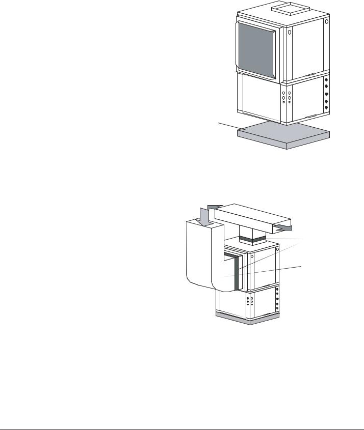
Figure 7: Vertical Unit Mounting
Air Pad or Extruded polystyrene insulation board
Figure 8: Typical Vertical Unit Installation
Using Ducted Return Air
Internally insulate supply duct for first 4’ [1.2m] each way to reduce noise
 Use turning vanes in supply transition
Flexible canvas duct connector to reduce noise and vibration
Rounded return transition
Rev 3/27/00
Internally insulate return transition duct to reduce noise
9
Installation, Operation & Maintenance |
HEV/H SERIES |
Heat Controller, Inc. |
|
|
|
VERTICAL INSTALLATION
Sound Attenuation for Vertical Units
Sound attenuation is achieved by enclosing the unit within a small mechanical room or a closet. Additional measures for sound control include the following:
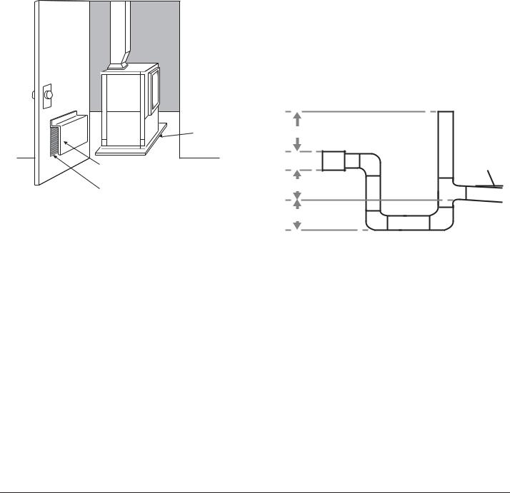
1.Mount the unit so that the return air inlet is 90° to the return air grille. Refer to Figure 9. Install a sound baffle as illustrated to reduce line-of sight sound transmitted through return air grilles.
2.Mount the unit on a rubber or neoprene isolation pad to minimize vibration transmission to the building structure.
Figure 9: Vertical Sound Attenuation
Jtpmbujpo!Qbe |
Jotvmbufe!Tpvoe!Cbggmf |
)Pqfo!Cpui!Foet!boe!Cpuupn* |
Sfuvso!Bjs!Mpvwfs!ps!Hsjmmf |
Condensate Piping for Vertical Units
Install condensate trap at each unit with the top of the trap positioned below the unit condensate drain connection as shown in Figure 4. Design the depth of the trap (waterseal) based upon the amount of External Static Pressure (ESP) capability of the blower (where 2 inches [51mm] of ESP capability requires 2 inches [51mm] of trap depth). As a general rule, 1 1/2 inch [38mm] trap depth is the minimum.
Each unit must be installed with its own individual trap and connection to the condensate line (main) or riser. Provide a means to flush or blow out the condensate line. DO NOT install units with a common trap and/or vent.
Always vent the condensate line when dirt or air can collect in the line or a long horizontal drain line is required. Also vent when large units are working against higher external static pressure than other units connected to the same condensate main since this may cause poor drainage for all units on
the line. WHEN A VENT IS INSTALLED IN THE DRAIN LINE, IT MUST BE LOCATED AFTER THE TRAP IN THE DIRECTION OF THE CONDENSATE FLOW.
Figure 4: Vertical Condensate Drain
3HU )RRW
* Some units include a painted drain connection. Using a threaded pipe or similar device to clear any excess paint accumulated inside this fitting may ease final drain line installation.
10
Heat Controller, Inc. |
HEV/H SERIES |
Installation, Operation & Maintenance |
|
|
|
VERTICAL INSTALLATION
Horizontal Unit Location
Packaged units are not designed for outdoor installation. Locate the unit in an INDOOR area that allows enough space for service personnel to perform typical maintenance or repairs without removing unit from the ceiling. Horizontal units are typically installed above a false ceiling or in a ceiling plenum. Never install units in areas subject to freezing or where humidity levels could cause cabinet condensation (such as unconditioned spaces subject to 100% outside air). Consideration should be given to access for easy removal of the filter and access panels. Provide sufficient room to make water, electrical, and duct connection(s).
If the unit is located in a confined space, such as a closet, provisions must be made for return air to freely enter the space by means of a louvered door or any other method. Any access panel screws that would be difficult to remove after the unit is installed should be removed prior to setting the unit. Refer to Figures 7a and 7b for an illustration of a typical installation. Refer to unit catalog specifications for dimensional data.
Conform to the following guidelines when selecting a unit location:
1.Provide a hinged access door in concealed-spline or plaster ceilings. Provide removable ceiling tiles in T-bar or lay-in ceilings. Refer to horizontal unit dimensions for specific series and model in unit catalog specifications. Size the access opening to accommodate the service technician during the removal or replacement of the compressor and the removal or installation of the unit itself.
2.Provide access to hanger brackets, water valves and fittings. Provide screwdriver clearance to access panels, discharge collars and all electrical connections.
3.DO NOT obstruct the space beneath the unit with piping, electrical cables and other items that prohibit future removal of components or the unit itself.
4.Use a manual portable jack/lift to lift and support the weight of the unit during installation and servicing.
The installation of geothermal heat pump units and all associated components, parts and accessories which make up the GHP system shall be in accordance with the regulations of ALL authorities having jurisdiction and MUST conform to all applicable codes. It is the responsibility of the installing contractor to determine and comply with ALL applicable codes and regulations.
Mounting Horizontal Units
Horizontal units have hanger kits pre-installed from the factory as shown in Figure 5. Figures 7a and 7b shows a typical horizontal unit installation.
Horizontal heat pumps are typically suspended above a ceiling or within a soffit using field supplied, threaded rods sized to support the weight of the unit.
Use four (4) field supplied threaded rods and factory provided vibration isolators to suspend the unit. Hang the unit clear
of the floor slab above and support the unit by the mounting bracket assemblies only. DO NOT attach the unit flush with the floor slab above.
Pitch the unit toward the drain as shown in Figure 6 to improve the condensate drainage. On small units (less than 2.5 Tons/8.8 kW) ensure that unit pitch does not cause condensate leaks inside the cabinet.
NOTE: The top panel of a horizontal unit is a structural component. The top panel of a horizontal unit must never be removed from an installed unit unless the unit is properly supported from the bottom. Otherwise, damage to the unit cabinet may occur.
Figure 5: Hanger Bracket
> PP@ 7KUHDGHG 
5RG E\ RWKHUV
9LEUDWLRQ ,VRODWRUIDFWRU\ VXSSOLHG
:DVKHU  E\ RWKHUV


'RXEOH +H[ 1XWV 
 E\ RWKHUV
Figure 6: Horizontal Unit Pitch
1/4” (6.4mm) pi  per foot for drai

 Drain
Drain
Connection
11
Installation, Operation & Maintenance |
HEV/H SERIES |
Heat Controller, Inc. |
|
|
|
HORIZONTAL INSTALLATION
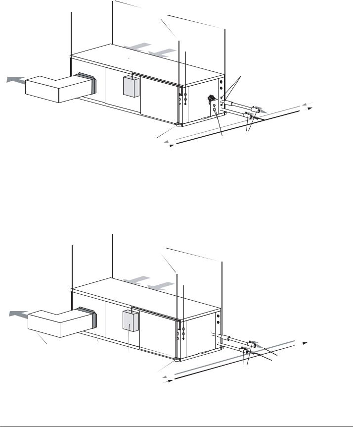
Figure 7a: Typical Closed Loop Horizontal Unit Installation
 3/8" [10mm] threaded rods (by others)
|
Return Air |
Thermostat |
|
|
|
||
|
|
Wiring |
|
|
Power Wiring |
|
|
|
|
Water |
|
Supply Air |
|
Pressure Ports |
|
|
Unit Power |
|
|
Insulated supply duct with |
Flexible Duct |
|
|
Connector |
|
||
at least one 90 deg elbow |
|
||
Unit Power |
Water Out |
||
to reduce air noise |
|||
Disconnect |
Water In |
||
|
|||
|
(by others) |
||
|
Ball Valves |
||
|
Unit Hanger |
||
|
Flush |
||
|
|
Ports |
Air Coil - To obtain maximum performance, the air coil should be cleaned before start-up. A 10% solution of dishwasher detergent and water is recommended for both sides of the coil. A thorough water rinse should follow.
Figure 7b: Typical Ground Water Horizontal Unit Installation
Supply Air
Insulated supply duct with at least one 90 deg elbow to reduce air noise
 3/8" [10mm] threaded rods (by others)
Return Air
Thermostat
Wiring
Power Wiring
Unit Power 
Building
 Loop
Loop
Flexible Duct |
|
|
Connector |
|
|
Unit Power |
Water Out |
|
Disconnect |
Water In |
|
(by others) |
||
Ball Valves |
||
Unit Hanger |
||
|
12

Heat Controller, Inc. |
HEV/H SERIES |
Installation, Operation & Maintenance |
|
|
|
FIELD CONVERSION OF AIR DISCHARGE
Field Conversion of Air Discharge
Overview - Horizontal units can be field converted between side (straight) and back (end) discharge using the instructions below.
Note: It is not possible to field convert return air between left or right return models due to the necessity of refrigeration copper piping changes.
Preparation - It is best to field convert the unit on the ground before hanging. If the unit is already hung it should be taken down for the field conversion.
Side to Back Discharge Conversion
1.Place unit in well lit area. Remove the screws as shown in Figure 8 to free top panel and discharge panel.
2.Lift out the access panel and set aside. Lift and rotate the discharge panel to the other position as shown, being careful with the blower wiring.
3.Check blower wire routing and connections for tension or contact with sheet metal edges. Reroute if necessary.
4.Check refrigerant tubing for contact with other components.
5.Reinstall top panel and screws noting that the location for some screws will have changed.
6.Manually spin the fan wheel to ensure that the wheel is not rubbing or obstructed.
7.Replace access panels.
Back to Side Discharge Conversion - If the discharge is changed from back to side, use above instruction noting that illustrations will be reversed.
Left vs. Right Return - It is not possible to field convert return air between left or right return models due to the necessity of refrigeration copper piping changes. However, the conversion process of side to back or back to side discharge for either right or left return configuration is the same. In some cases, it may be possible to rotate the entire unit 180 degrees if the return air connection needs to be on the opposite side. Note that rotating the unit will move the piping to the other end of the unit.
Figure 8: Left Return Side to Back
Water |
Remove Screws |
Connection End |
|
Return Air
Side Discharge 
Water
Connection End
Rotate
Return Air
Move to Side
Replace Screws
Water
Connection End
Back Discharge
Figure 9: Right Return Side to Back
Return Air
Supply Duct
Return Air
Drain
Discharge Air
Water
Connection End
Side Discharge
Water
Connection End
Return Air
Drain
Discharge Air
Back Discharge
13
Installation, Operation & Maintenance |
HEV/H SERIES |
Heat Controller, Inc. |
|
|
|
WATER CONNECTION INSTALLATION
External Flow Controller Mounting
The Flow Controller can be mounted beside the unit as shown in Figure 12. Review the Flow Controller installation manual for more details.
Water Connections-Residential HER Models
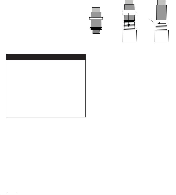
Models utilize swivel piping fittings for water connections that are rated for 450 psi (3101 kPa) operating pressure. The connections have a rubber gasket seal similar to a garden hose gasket, which when mated to the flush end of most 1” threaded male pipe fittings provides a leakfree seal without the need for thread sealing tape or joint compound. Insure that the rubber seal is in the swivel connector prior to attempting any connection (rubber seals are shipped attached to the swivel connector). DO NOT OVER TIGHTEN or leaks may occur.
The female locking ring is threaded onto the pipe threads
which holds the male pipe end against the rubber gasket, and seals the joint. HAND TIGHTEN ONLY! DO NOT OVERTIGHTEN!
Figure 11: Water Connections
Hand Tighten
Only!
Swivel Nut Do Not
Overtighten!

 Stainless steel snap ring
Gasket |
Brass Adaptor |
GROUND-LOOP HEAT PUMP APPLICATIONS
ѥ CAUTION! ѥ
CAUTION! The following instructions represent industry accepted installation practices for closed loop earth coupled heat pump systems. Instructions are provided
to assist the contractor in installing trouble free ground loops. These instructions are recommendations only. State/provincial and local codes MUST be followed and
installation MUST conform to ALL applicable codes. It is the responsibility of the installing contractor to determine and comply with ALL applicable codes and regulations.
Pre-Installation
Prior to installation, locate and mark all existing underground utilities, piping, etc. Install loops for new construction before sidewalks, patios, driveways, and other construction has begun. During construction, accurately mark all ground loop piping on the plot plan as an aid in avoiding potential future damage to the installation.
Piping Installation
The typical closed loop ground source system is shown in Figure 12. All earth loop piping materials should be limited to polyethylene fusion only for in-ground sections of the loop. Galvanized or steel fittings should not be used at any time due to their tendency to corrode. All plastic to metal threaded fittings should be avoided due to their potential to leak in earth coupled applications. A flanged fitting should be substituted. P/T plugs should be used so that flow can be measured using the pressure drop of the unit heat exchanger.
Earth loop temperatures can range between 25 and 110°F [-4 to 43°C]. Flow rates between 2.25 and 3 gpm per ton [2.41 to 3.23 l/m per kW] of cooling capacity recommended in these applications.
Test individual horizontal loop circuits before backfilling. Test vertical U-bends and pond loop assemblies prior to installation. Pressures of at least 100 psi [689 kPa] should be used when testing. Do not exceed the pipe pressure rating. Test entire system when all loops are assembled.
Flushing the Loop
Once piping is completed between the unit, Flow Controller and the ground loop (Figure 12), the loop is ready for final purging and charging. A flush cart with at least a 1.5 hp [1.1 kW] pump is required to achieve enough fluid velocity in the loop piping system to purge air and dirt particles. An antifreeze solution is used in most areas to prevent freezing. All air and debris must
be removed from the earth loop piping before operation. Flush the loop with a high volume of water at a minimum velocity of 2 fps (0.6 m/s) in all piping. The steps below must be followed for proper flushing.
1.Fill loop with water from a garden hose through the flush cart before using the flush cart pump to insure an even fill.
2.Once full, the flushing process can begin. Do not allow the water level in the flush cart tank to drop below the pump inlet line to avoid air being pumped back out to the earth loop.
3.Try to maintain a fluid level in the tank above the return tee so that air cannot be continuously mixed back into the fluid. Surges of 50 psi (345 kPa) can be used to help purge air pockets by simply shutting off the return valve going into the flush cart reservoir. This “dead heads” the pump to 50 psi (345 kPa). To purge, dead head the pump until maximum pumping
14
 Loading...