


Owner’s Manual
Installation and Operation
Models:
SL-750TRS-IPI-D
SL-550TRS-IPI-D
SL-350TRS-C
CAUTION
DO NOT DISCARD THIS MANUAL
• Important operating and |
• Read, understand and follow |
• Leave this manual with |
maintenance instruc- |
these instructions for safe |
party responsible for |
tions included. |
installation and operation. |
use and operation. |
DO DISCARDNOT
 WARNING: If the information in these instructions is not followed exactly, a fire or explosion may result causing property damage, personal injury, or death.
•Do not store or use gasoline or other flammable vapors and liquids in the vicinity of this or any other appliance.
•What to do if you smell gas
-Do not try to light any appliance
-Do not touch any electrical switch. Do not use any phone in your building.
-Immediately call your gas supplier from a neighbor’s phone. Follow the gas supplier’s instructions.
-If you cannot reach your gas supplier, call the fire department.
•Installation and service must be performed by a qualified installer, service agency, or the gas supplier.
This appliance may be installed as an OEM installation in manufactured home (USA only) or mobile home and must be installed in accordance with the manufacturer’s instructions and the manufactured home construction and safety standard, Title 24 CFR, Part 3280 or Standard for Installation in Mobile Homes, CAN/CSA Z240MH.
This appliance is only for use with the type(s) of gas indicated on the rating plate.
 WARNING
HOT! DO NOT TOUCH.
SEVERE BURNS MAY RESULT. CLOTHING IGNITION MAY RESULT.
Glass and other surfaces are hot during operation and cool down.
•Keep children away.
•CAREFULLY SUPERVISE children in same room as appliance.
•Alert children and adults to hazards of high temperatures.
•Do NOT operate with protective barriers open or removed.
•Keep clothing, furniture, draperies and other combustibles away.
This appliance has been supplied with an integral barrier to prevent direct contact with the fixed glass panel. Do NOT operate the appliance with the barrier removed.
Contact your dealer or Hearth & Home Technologies if the barrier is not present or help is needed to properly install one.
In the Commonwealth of Massachusetts:
•installation must be performed by a licensed plumber or gas fitter;
See Table of Contents for location of additional |
Í |
Commonwealth of Massachusetts requirements. |
Installation and service of this appliance should be performed by qualified personnel. Hearth & Home Technologies suggests NFI certified or factory-trained professionals, or technicians supervised
by an NFI certified professional.
Heat & Glo • SL-350TRS-C, SL-550/750TRS-IPI-D • 2065-985 Rev. J • 5/06 |
1 |
SAFETY AND WARNING INFORMATION
READ and UNDERSTAND all instructions carefully
!before starting the installation. FAILURE TO FOLLOW these installation instructions may result in a possible fire hazard and will void the warranty.
!Prior to the first firing of the appliance, READ the Using Your Appliance section of the Owners Guide.
DO NOT USE this appliance if any part has been
!under water. Immediately CALL a qualified service technician to inspect the unit and to replace any part of the control system and any gas control which has been under water.
!THIS UNIT IS NOT FOR USE WITH SOLID FUEL.
Installation and repair should be PERFORMED by a
!qualified service person. The appliance and venting system should be INSPECTED before initial use and at least annually by a professional service person. More frequent cleaning may be required due to excessive lint from carpeting, bedding material, etc. It is IMPERATIVE that the unit’s control compartment, burners, and circulating air passageways BE KEPT CLEAN to provide for adequate combustion and ventilation air.
Always KEEP the appliance clear and free from
!combustible materials, gasoline, and other flammable vapors and liquids.
!NEVER OBSTRUCT the flow of combustion and ventilation air. Keep the front of the appliance CLEAR of all obstacles and materials for servicing and proper operations.
Due to the high temperature, the appliance should
!be LOCATED out of traffic areas and away from furniture and draperies. Clothing or flammable material SHOULD NOT BE PLACED on or near the appliance.
!Children and adults should be ALERTED to the hazards of high surface temperature and should STAY AWAY to avoid burns or clothing ignition. Young children should be CAREFULLY SUPERVISED when they are in the same room as the appliance.
These units MUST use one of the vent systems
!described in the Installing the Appliance section of the Installers Guide. NO OTHER vent systems or components MAY BE USED.
This gas appliance and vent assembly MUST be
!vented directly to the outside and MUST NEVER be attached to a chimney serving a separate solid fuel burning appliance. Each gas appliance MUST USE a separate vent system. Common vent systems are
PROHIBITED.
INSPECT the external vent cap on a regular basis to
!make sure that no debris is interfering with the air flow.
!The glass door assembly MUST be in place and sealed, and the trim door assembly MUST be in place on the appliance before the unit can be placed into safe operation.
DO NOT OPERATE this appliance with the glass
!door removed, cracked, or broken. Replacement of the glass door should be performed by a licensed or qualified service person. DO NOT strike or slam the glass door.
!The glass door assembly SHALL ONLY be replaced as a complete unit, as supplied by the gas appliance manufacturer. NO SUBSTITUTE material may be used.
!DO NOT USE abrasive cleaners on the glass door assembly. DO NOT ATTEMPT to clean the glass door when it is hot.
Turn off the gas before servicing this appliance. It is
!recommended that a qualified service technician perform an appliance check-up at the beginning of each heating season.
!Any safety screen or guard removed for servicing must be replaced before operating this appliance.
!DO NOT place furniture or any other combustible household objects within 36 inches of the appliance front.
2 |
Heat & Glo • SL-350TRS-C, SL-550/750TRS-IPI-D • 2065-985 Rev. J • 5/06 |
TABLE OF CONTENTS |
|
|
Safety and Warning Information ......................................................... |
2 |
|
ÎService Parts Lists ................................................................................. |
4 |
|
Section 1: Approvals and Codes ........................................................ |
12 |
|
Appliance Certification ........................................................................... |
12 |
|
Installation Codes .................................................................................. |
12 |
|
High Altitude Installations ...................................................................... |
12 |
|
Î Requirements for the Commonwealth of Massachusetts........................ |
13 |
|
Section 2: Getting Started .................................................................. |
14 |
|
Introducing the Heat & Glo Gas Appliances ........................................... |
14 |
|
Pre-installation Preparation .................................................................... |
14 |
|
Section 3: Installing the Appliance ................................................... |
18 |
|
Constructing the Appliance Chase ......................................................... |
18 |
|
Step 1 |
Locating the Appliance .......................................................... |
18 |
Step 2 |
Framing the Appliance .......................................................... |
19 |
Step 3 |
Installing the Vent System .................................................... |
22 |
|
A. Vent System Approvals ................................................... |
22 |
|
B. Installing Vent Components ............................................. |
32 |
|
C. Vent Termination .............................................................. |
35 |
Step 4 |
Positioning, Leveling, and |
|
|
Securing the Appliance ......................................................... |
38 |
Step 5 |
The Gas Control Systems ..................................................... |
38 |
Step 6 |
The Gas Supply Line ............................................................. |
39 |
Step 7 |
Gas Pressure Requirements ................................................. |
39 |
Step 8 |
Wiring the Appliance ............................................................. |
40 |
Step 9 |
Finishing ............................................................................... |
42 |
Step 10 |
Installing Trim, Logs, and Ember Material ............................. |
43 |
|
Installing the Trim .................................................................. |
43 |
|
Positioning the Logs ............................................................. |
43 |
|
Shutter Settings .................................................................... |
43 |
|
Placing the Ember Material ................................................... |
43 |
|
Glass Specifications ............................................................. |
43 |
Step 11 Before Lighting the Appliance ................................................ |
44 |
|
Step 12 |
Lighting the Appliance ........................................................... |
44 |
After the Installation ............................................................................... |
44 |
|
Section 4: Maintaining and Servicing Your Appliance ................... |
45 |
|
|
Î= Contains updated information. |
|
Heat & Glo • SL-350TRS-C, SL-550/750TRS-IPI-D • 2065-985 Rev. J • 5/06 |
3 |
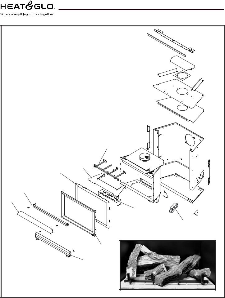
Service Parts
SL-350TRS-C
(NG, LP) Exploded Parts Diagram |
Beginning Manufacturing Date: 4-01 |
|
Ending Manufacturing Date: ______ |
4
5
1
14
6
2
13
|
7 Log Set Assembly |
|
|
3 |
|
15 |
12 |
8 |
|
|
|
11 10 9
Part number list on following page.
4 |
Heat & Glo • SL-350TRS-C, SL-550/750TRS-IPI-D • 2065-985 Rev. J • 5/06 |
(NG, LP) Service Parts List |
SL-350TRS-C |
IMPORTANT: THIS IS DATED INFORMATION. The most current information is located on your dealers VIP site. When ordering, supply serial and model numbers to ensure correct service parts.
ITEM |
STANDING PILOT |
|
SERIAL # |
PART NUMBER |
||
|
Burner Orifice NG (#43C) |
|
|
582-843 |
|
|
|
|
|
|
|
|
|
|
Burner Orifice LP (#53C) |
|
|
582-853 |
|
|
|
|
|
|
|
||
1 |
Glass Door Assembly |
|
|
GLA-350TRS |
||
|
|
|
|
|
|
|
2 |
Burner NG, LP |
|
|
540-234A |
|
|
|
|
|
|
|
|
|
3 |
Mesh Panel Door |
|
|
540-382A |
|
|
|
|
|
|
|
|
|
4 |
Log Grate |
|
|
540-361A |
|
|
|
|
|
|
|
|
|
5 |
Base Refractory |
PRE |
4/06 |
540-206T |
(Tan) |
|
POST |
4/06 |
2065-206 |
(Black) |
|||
|
|
|||||
6 |
Hood |
|
|
SRV540-174 |
||
|
|
|
|
|
|
|
7 |
Log Set Assembly |
|
|
LOGS-350 |
|
|
|
|
|
|
|
||
8 |
Log 1 |
|
|
SRV530-701 |
||
|
|
|
|
|
||
9 |
Log 2 |
|
|
SRV530-704 |
||
|
|
|
|
|
||
10 |
Log 3 |
|
|
SRV540-702 |
||
|
|
|
|
|
||
11 |
Log 4 |
|
|
SRV530-705 |
||
|
|
|
|
|
||
12 |
Log 5 |
|
|
SRV530-703 |
||
|
|
|
|
|
|
|
13 |
Junction Box |
PRE |
00251404 |
100-250A |
|
|
POST |
00251404 |
4021-013 |
|
|||
|
|
|
||||
14 |
Louver, Top |
|
|
540-256A |
|
|
|
|
|
|
|
|
|
15 |
Louver, Bottom |
|
|
540-257A |
|
|
|
|
|
|
|
|
|
|
Pilot Orifice NG |
|
|
446-505 |
|
|
|
|
|
|
|
|
|
|
Pilot Orifice LP |
|
|
446-517 |
|
|
|
|
|
|
|
|
|
|
Thermocouple |
|
|
446-511 |
|
|
|
|
|
|
|
|
|
|
Thermopile |
|
|
060-512 |
|
|
|
|
|
|
|
||
|
Conversion Kit NG |
|
|
NGK-350TRS-C |
||
|
|
|
|
|
||
|
Conversion Kit LP |
|
|
LPK-350TRS-C |
||
|
|
|
|
|
||
|
Vermiculite Embers |
|
|
MYSTIC-EMBERS |
||
|
|
|
|
|
|
|
|
Exhaust Restrictor |
|
|
530-299 |
|
|
|
|
|
|
|
|
|
|
Glass Latch Assembly |
|
|
386-122A |
|
|
|
|
|
|
|
|
|
|
Mineral Wool |
|
|
050-721 |
|
|
|
|
|
|
|
||
|
Touch up Paint |
|
|
TUP-GBK-12 |
||
|
|
|
|
|
|
|
Also see additional pages for valve assembly service part numbers.
Heat & Glo • SL-350TRS-C, SL-550/750TRS-IPI-D • 2065-985 Rev. J • 5/06 |
5 |
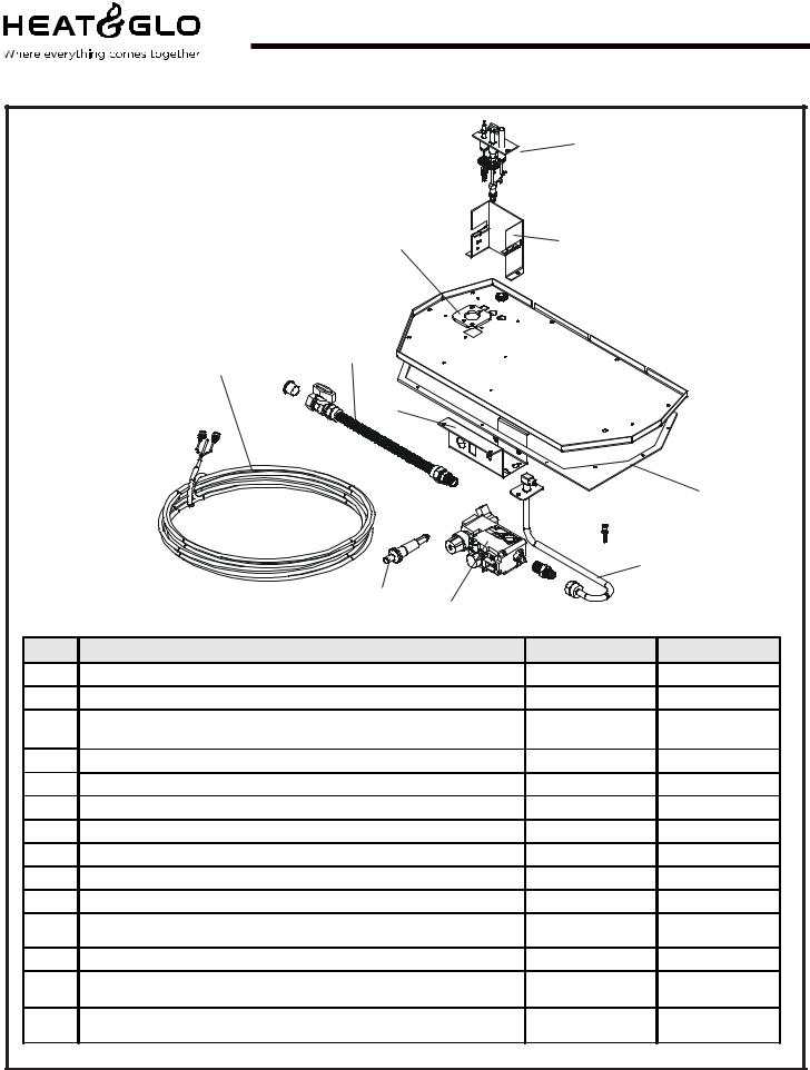
Service Parts |
SL-350TRS-C |
(NG, LP) Exploded Parts Diagram |
Beginning Manufacturing Date: 4-01 |
|
Ending Manufacturing Date: ______ |
|
4 |
Standing Pilot Ignition |
|
Valve Assembly |
|
2 |
10 |
|
3 |
7 |
|
|
|
|
|
|
|
|
|
|
|
|
5 |
|
|
|
|
|
|
|
6 |
|
|
|
|
|
9 |
|
|
1 |
8 |
|
|
|
|
|
|
|
|
ITEM |
|
DESCRIPTION |
|
SERIAL # |
PART NUMBER |
1 |
Piezo Ignitor |
|
|
|
291-513 |
2 |
Burner Neck Gasket |
|
|
|
2045-407 |
3 |
Thermostat Wire Assembly |
|
PRE |
00251404 |
N/A |
|
POST 00251404 |
2045-024 |
|||
|
|
|
|||
4 |
Pilot Assembly NG |
|
|
|
530-510A |
4 |
Pilot Assembly LP |
|
|
|
530-511A |
5 |
Valve Bracket |
|
|
|
2025-101 |
6 |
Valve Plate Gasket |
|
|
|
530-431 |
7 |
Flex Ball Valve Assembly |
|
|
|
302-320A |
8 |
Valve NG |
|
|
|
060-522 |
8 |
Valve LP |
|
|
|
060-523 |
9 |
Flexible Gas Connector |
|
PRE |
22099930 |
567-301A |
|
POST 22099930 |
530-302A |
|||
|
|
|
|||
10 |
Pilot Bracket |
|
|
|
530-164 |
|
ON/OFF Rocker Switch |
|
PRE |
00251404 |
060-511 |
|
|
POST 00251404 |
N/A |
||
|
|
|
|||
|
Wire Assembly |
|
PRE |
00251404 |
049-552A |
|
|
POST 00251404 |
N/A |
||
|
|
|
|||
6 |
Heat & Glo • SL-350TRS-C, SL-550/750TRS-IPI-D • 2065-985 Rev. J • 5/06 |

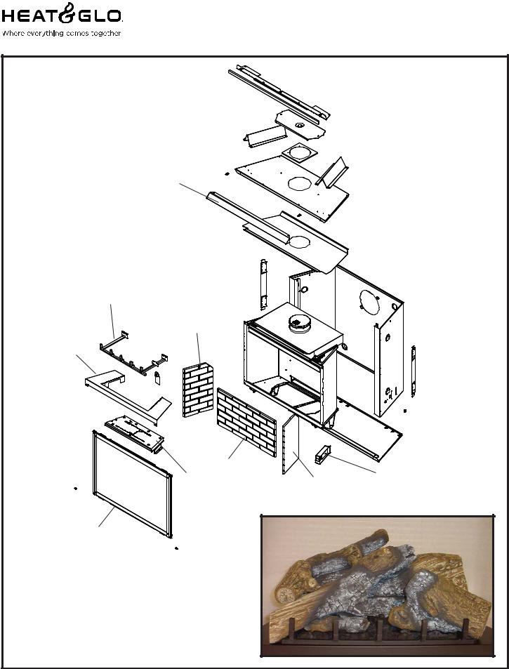
Service Parts |
SL-550TRS-IPI-D |
|
|
|
|
(NG, LP) Exploded Parts Diagram |
Beginning Manufacturing Date: 4-04 |
|
|
Ending Manufacturing Date: ______ |
|
Î
4
14
5
6
13 |
7 Log Set Assembly |
15 |
1 |
|
|
||
2 |
|
|
|
|
|
|
|
|
12 |
|
9 |
|
|
|
|
3 |
11 |
|
10 |
|
|
||
|
|
|
|
|
|
8 |
|
Part number list on following page.
Heat & Glo • SL-350TRS-C, SL-550/750TRS-IPI-D • 2065-985 Rev. J • 5/06 |
7 |
(NG, LP) Service Parts List |
SL-550TRS-IPI-D |
IMPORTANT: THIS IS DATED INFORMATION. The most current information is located on your dealers VIP site. When ordering, supply serial and model numbers to ensure correct service parts.
ITEM |
DESCRIPTION |
SERIAL # |
PART NUMBER |
|
|
|
|
|
Burner Orifice NG (#38C) |
|
582-838 |
|
|
|
|
|
Burner Orifice LP (#53C) |
|
582-853 |
|
|
|
|
1 |
Junction Box |
|
4021-013 |
2 |
Burner NG |
|
2065-005 |
|
|
|
|
2 |
Burner LP |
|
2065-006 |
|
|
|
|
3 |
Glass Door Assembly |
|
GLA-550TRS |
|
|
|
|
4 |
Log Grate |
|
2066-036 |
|
|
|
|
5 |
Base Refractory NG, LP |
|
2065-100 |
|
|
|
|
6 |
Hood |
|
SRV550-175 |
|
|
|
|
7 |
Log Set Assembly |
|
LOGS-550TRS-D |
|
|
|
|
8 |
Log 1 |
|
SRV2065-701 |
9 |
Log 2 |
|
SRV2065-702 |
|
|
|
|
10 |
Log 3 |
|
SRV2065-703 |
|
|
|
|
11 |
Log 4 |
|
SRV2065-704 |
|
|
|
|
12 |
Log 5 |
|
SRV2065-705 |
|
Refractory Kit |
|
BRICK-550TRS-D |
|
|
|
|
13 |
Refractory, Back |
|
SRV2044-711 |
|
|
|
|
14 |
Refractory, Left Side |
|
SRV2044-710 |
|
|
|
|
15 |
Refractory, Right Side |
|
SRV2044-712 |
|
|
|
|
|
Pilot Orifice NG |
|
446-505 |
|
|
|
|
|
Pilot Orifice LP |
|
446-517 |
|
|
|
|
|
Thermocouple |
|
446-511 |
|
|
|
|
|
Thermopile |
|
060-512 |
|
|
|
|
|
Mineral Wool |
|
050-721 |
|
|
|
|
|
Glass Latch |
|
386-122A |
|
|
|
|
|
Exhaust Restrictor |
|
530-299 |
|
|
|
|
|
Touch up Paint |
|
TUP-GBK-12 |
|
|
|
|
|
ACCESSORIES |
|
|
|
Fan Kit |
|
GFK-160A |
|
|
|
|
|
Extended Vertical Baffle Kit |
|
BAF-VERT |
|
Wall Switch Kit, Off-white |
|
WSK-21 |
|
|
|
|
|
Wall Switch Kit, White |
|
WSK-21-W |
|
|
|
|
|
Conversion Kit NG |
|
NGK-550TRS-IPID |
|
|
|
|
|
Conversion Kit LP |
|
LPK-550TRS-IPID |
|
Vermiculite Embers |
|
MYSTIC-EMBERS |
|
|
|
|
Í
Í
Í
Also see additional pages for valve assembly service part numbers.
8 |
Heat & Glo • SL-350TRS-C, SL-550/750TRS-IPI-D • 2065-985 Rev. J • 5/06 |
Service Parts |
SL-750TRS-IPI-D |
|
|
(NG, LP) Exploded Parts Diagram |
Beginning Manufacturing Date: 4-04 |
|
Ending Manufacturing Date: ______ |
Î
6
4
14
5
2 |
13 |
15 |
1 |
|
7 Log Set Assembly
3
12 |
9 |
11 10
Part number list on following page.
8
Heat & Glo • SL-350TRS-C, SL-550/750TRS-IPI-D • 2065-985 Rev. J • 5/06 |
9 |
(NG, LP) Service Parts List |
SL-750TRS-IPI-D |
IMPORTANT: THIS IS DATED INFORMATION. The most current information is located on your dealers VIP site. When ordering, supply serial and model numbers to ensure correct service parts.
ITEM |
DESCRIPTION |
SERIAL # |
PART NUMBER |
|
|
|
|
|
Burner Orifice NG (#36C) |
|
582-836 |
|
|
|
|
|
Burner Orifice LP (#52C) |
|
582-852 |
|
|
|
|
1 |
Junction Box |
|
4021-013 |
|
|
|
|
2 |
Burner NG |
|
2066-005 |
|
|
|
|
2 |
Burner LP |
|
2065-006 |
|
|
|
|
3 |
Glass Door Assembly |
|
GLA-750TRS |
|
|
|
|
4 |
Log Grate |
|
2066-036 |
|
|
|
|
5 |
Base Refractory NG, LP |
|
2066-100 |
|
|
|
|
6 |
Hood |
|
SRV530-175 |
|
|
|
|
7 |
Log Set Assembly |
|
LOGS-750TRS-D |
|
|
|
|
8 |
Log 1 |
|
SRV2065-701 |
|
|
|
|
9 |
Log 2 |
|
SRV2066-702 |
|
|
|
|
10 |
Log 3 |
|
SRV2066-703 |
|
|
|
|
11 |
Log 4 |
|
SRV2066-704 |
|
|
|
|
12 |
Log 5 |
|
SRV2066-705 |
|
|
|
|
|
Refractory Kit |
|
BRICK-750TRS-D |
|
|
|
|
13 |
Refractory, Back |
|
SRV2045-711 |
|
|
|
|
14 |
Refractory, Left Side |
|
SRV2045-710 |
|
|
|
|
15 |
Refractory, Right Side |
|
SRV2045-712 |
|
|
|
|
|
Mineral Wool |
|
050-721 |
|
|
|
|
|
Glass Latch Assembly |
|
386-122A |
|
|
|
|
|
Exhaust Restrictor |
|
530-299 |
|
|
|
|
|
Touch up Paint |
|
TUP-GBK-12 |
|
|
|
|
|
ACCESSORIES |
|
|
|
|
|
|
|
Fan Kit |
|
GFK-160A |
|
|
|
|
|
Extended Vertical Baffle Kit |
|
BAF-VERT |
|
|
|
|
|
Wall Switch Kit, Off-white |
|
WSK-21 |
|
|
|
|
|
Wall Switch Kit, White |
|
WSK-21-W |
|
|
|
|
|
Conversion Kit NG |
|
NGK-750TRS-IPID |
|
|
|
|
|
Conversion Kit LP |
|
LPK-750TRS-IPID |
|
|
|
|
|
Vermiculite Embers |
|
MYSTIC-EMBERS |
|
|
|
|
Í
Í
Í
Also see additional pages for valve assembly service part numbers.
10 |
Heat & Glo • SL-350TRS-C, SL-550/750TRS-IPI-D • 2065-985 Rev. J • 5/06 |
Service Parts SL-750TRS-IPI-D, SL-550TRS-IPI-D
(NG, LP) Exploded Parts Diagram |
Beginning Manufacturing Date: 4-04 |
|
Ending Manufacturing Date: ______ |
Intermittent Pilot Ignition
Valve Assembly
 4
4
6
1 |
15 |
14
|
2 |
|
|
|
|
5 |
|
|
|
|
|
|
|
|
|
|
|
|
|
|
|
|
|
|
|
|
|
9 |
12 |
|
|
|
|
|
|
7 |
|
|
|
|
|
|
|
|
|
|
|
|
|
|
|
|
|
|
|
3 |
8 |
10 |
13 |
|
|
|
|
|
|
|
|||
|
|
|
|
|
|
11 |
|
||
|
|
|
|
|
|
|
|
|
|
ITEM / |
|
|
|
|
|
DESCRIPTION |
|
SERIAL # |
PART NUMBER |
PIÈCE |
|
|
|
|
|
|
/N°DE SÉRIE |
/ N° DE PIÈCE |
|
|
|
|
|
|
|
|
|||
1 |
Burner Neck Gasket |
/ Joint de Cou de Brûleur |
|
|
2045-407 |
||||
2 |
Thermostat Wire Assembly / L'Assemblée de Fil de thermostat |
|
2045-024 |
||||||
3 |
Wire Assembly / Module de fil |
|
|
2012-206 |
|||||
4 |
Pilot Assembly NG / Module de veilleuse GN |
|
|
4021-025 |
|||||
4 |
Pilot Assembly LP / Module de veilleuse PL |
|
|
4021-026 |
|||||
5 |
Valve Bracket |
/ |
Parenthèse de Valve |
|
|
2025-101 |
|||
6 |
Ground Strap |
/ |
Courroie de Raison(Terre) |
|
|
385-512 |
|||
7 |
Flex Ball Valve Assembly / |
Fléchir l'Assemblée de Soupape de Balle |
|
302-320A |
|||||
8 |
Valve NG / Valve |
GN |
|
|
|
750-500 |
|||
8 |
Valve LP / Valve |
PL |
|
|
|
|
750-501 |
||
9 |
Flexible Gas Connector / |
Tuyau à gaz flexible |
|
|
530-302A |
||||
10 |
Module / Module |
|
|
|
|
|
593-592 |
||
11 |
Wire Assembly / Module de fil |
|
|
593-590A |
|||||
12 |
Battery Pack |
/ |
Paquet de Batterie(Pile) |
|
|
593-594A |
|||
13 |
3 Volt Transformer |
/ |
3 Transformateur de Volt |
|
|
593-593A |
|||
14 |
Valve Plate Gasket / |
Joint de Plat de Valve |
|
|
530-431 |
||||
15 |
Pilot Bracket / Parenthèse Pilote |
|
|
2065-117 |
|||||
Heat & Glo • SL-350TRS-C, SL-550/750TRS-IPI-D • 2065-985 Rev. J • 5/06 |
11 |
1Approvals and Codes
Appliance Certification
The Heat & Glo appliance models discussed in this Installers Guide have been tested to certification standards and listed by the applicable laboratories.
Certification
MODELS: SL-750TRS-IPI-D,SL-550TRS-IPI-D, SL-350TRS-C
LABORATORY: Underwriters Laboratories TYPE: Direct Vent Gas Fireplace Heater STANDARD: ANSI Z21.88•CSA2.33•UL307B
NOTE: THESE MODELS ARE UL LISTED TO UL307B, THE STANDARD FOR GAS-BURNING HEATING APPLIANCES FOR MANUFACTURED HOMES AND RECREATIONAL VEHICLES.
High Altitude Installations
U.L. Listed gas appliances are tested and approved without requiring changes for elevations from 0 to 2,000 feet in the U. S. A. and in Canada.
When installing this appliance at an elevation above 2,000 feet, it may be necessary to decrease the input rating by changing the existing burner orifice to a smaller size. Input rate should be reduced by 4% for each 1000 feet above a 2000 foot elevation in the U.S.A. or 10% for elevations between 2000 and 4500 feet in Canada. If the heating value of the gas has been reduced, these rules do not apply. To identify the proper orifice size, check with the local gas utility.
If installing this appliance at an elevation above 4,500 feet (in Canada), check with local authorities.
Installation Codes
The appliance installation must conform to local codes. Before installing the appliance, consult the local building code agency to ensure that you are in compliance with all applicable codes, including permits and inspections.
In the absence of local codes, the appliance installation must conform to the National Fuel Gas Code ANSI Z223.1 (in the United States) or the CAN/CGA-B149 Installation Codes (in Canada). The appliance must be electrically grounded in accordance with local codes or, in the absence of local codes with the National Electric Code ANSI/NFPA No. 70 (in the United States), or to the CSA C22.1 Canadian Electric Code (in Canada).
These models may be installed in a bedroom or bed-sitting room in the U.S.A. and Canada.
Heat & Glo Quality Systems registered by SGS ICS
12 |
Heat & Glo • SL-350TRS-C, SL-550/750TRS-IPI-D • 2065-985 Rev. J • 5/06 |
NOTE: The following requirements reference various Massachusetts and national codes not contained in this document.
Î Requirements for the Commonwealth of
Massachusetts
For all side wall horizontally vented gas fueled equipment installed in every dwelling, building or structure used in whole or in part for residential purposes, including those owned or operated by the Commonwealth and where the side wall exhaust vent termination is less than seven (7) feet above finished grade in the area of the venting, including but not limited to decks and porches, the following requirements shall be satisfied:
Installation of Carbon Monoxide Detectors
At the time of installation of the side wall horizontal vented gas fueled equipment, the installing plumber or gasfitter shall observe that a hard wired carbon monoxide detector with an alarm and battery back-up is installed on the floor level where the gas equipment is to be installed. In addition, the installing plumber or gasfitter shall observe that a battery operated or hard wired carbon monoxide detector with an alarm is installed on each additional level of the dwelling, building or structure served by the side wall horizontal vented gas fueled equipment. It shall be the responsibility of the property owner to secure the services of qualified licensed professionals for the installation of hard wired carbon monoxide detectors.
In the event that the side wall horizontally vented gas fueled equipment is installed in a crawl space or an attic, the hard wired carbon monoxide detector with alarm and battery back-up may be installed on the next adjacent floor level.
In the event that the requirements of this subdivision can not be met at the time of completion of installation, the owner shall have a period of thirty (30) days to comply with the above requirements; provided, however, that during said thirty (30) day period, a battery operated carbon monoxide detector with an alarm shall be installed.
Approved Carbon Monoxide Detectors
Each carbon monoxide detector as required in accordance with the above provisions shall comply with NFPA 720 and be ANSI/UL 2034 listed and IAS certified.
Signage
A metal or plastic identification plate shall be permanently mounted to the exterior of the building at a minimum height of eight (8) feet above grade directly in line with the exhaust vent terminal for the horizontally vented gas fueled heating appliance or equipment. The sign shall read, in print size no less than one-half (1/2) inch in size, “GAS
VENT DIRECTLY BELOW. KEEP CLEAR OF ALL OBSTRUCTIONS”.
Inspection
The state or local gas inspector of the side wall horizontally vented gas fueled equipment shall not approve the installation unless, upon inspection, the inspector observes carbon monoxide detectors and signage installed in accordance with the provisions of 248 CMR 5.08(2)(a)1 through 4.
Exemptions
The following equipment is exempt from 248 CMR 5.08(2)(a)1 through 4:
•The equipment listed in Chapter 10 entitled “Equipment Not Required To Be Vented” in the most current edition of NFPA 54 as adopted by the Board; and
•Product Approved side wall horizontally vented gas fueled equipment installed in a room or structure separate from the dwelling, building or structure used in whole or in part for residential purposes.
MANUFACTURER REQUIREMENTS
Gas Equipment Venting System Provided
When the manufacturer of Product Approved side wall horizontally vented gas equipment provides a venting system design or venting system components with the equipment, the instructions provided by the manufacturer for installation of the equipment and the venting system shall include:
•Detailed instructions for the installation of the venting system design or the venting system components; and
•A complete parts list for the venting system design or venting system.
Gas Equipment Venting System NOT Provided
When the manufacturer of a Product Approved side wall horizontally vented gas fueled equipment does not provide the parts for venting the flue gases, but identifies “special venting systems”, the following requirements shall be satisfied by the manufacturer:
•The referenced “special venting system” instructions shall be included with the appliance or equipment installation instructions; and
•The “special venting systems” shall be ProductApproved by the Board, and the instructions for that system shall include a parts list and detailed installation instructions.
A copy of all installation instructions for all Product Approved side wall horizontally vented gas fueled equipment, all venting instructions, all parts lists for venting instructions, and/or all venting design instructions shall remain with the appliance or equipment at the completion of the installation.
See Gas Connection section for additional Commonwealth of Massachusetts requirements.
Heat & Glo • SL-350TRS-C, SL-550/750TRS-IPI-D • 2065-985 Rev. J • 5/06 |
13 |

2Getting Started
Introducing the Heat & Glo Gas Appliances
Heat & Glo direct vent gas appliances are designed to operate with all combustion air siphoned from outside of the building and all exhaust gases expelled to the outside.
The information contained in this Installers Guide, unless noted otherwise, applies to all models and gas control systems. Gas appliance diagrams, including the dimensions, are shown in this section.
Pre-install Preparation
This gas appliance and its components are tested and safe when installed in accordance with this Installers Guide. Report to your dealer any parts damaged in shipment, particularly the condition of the glass. Do not install any unit with damaged, incomplete, or substitute parts.
The vent system components and trim doors are shipped in separate packages. The gas logs are packaged separately and must be field installed.
Read all of the instructions before starting the installation. Follow these instructions carefully during the installation to ensure maximum safety and benefit. Failure to follow these instructions will void the owner’s warranty and may present a fire hazard.
The Heat & Glo Warranty will be voided by, and Heat & Glo disclaims any responsibility for, the following actions:
•Installation of any damaged appliance or vent system component.
•Modification of the appliance or direct vent system.
•Installation other than as instructed by Heat & Glo.
•Improper positioning of the gas logs or the glass door.
•Installation and/or use of any component part not manufactured and approved by Heat & Glo, not withstanding any independent testing laboratory or other party approval of such component part or accessory.
ANY SUCH ACTION MAY POSSIBLY CAUSE A FIRE HAZARD.
When planning a appliance installation, it’s necessary to determine:
•Where the unit is to be installed.
•The vent system configuration to be used.
•Gas supply piping.
•Electrical wiring.
•Framing and finishing details.
•Whether optional accessories—devices such as a fan, wall switch, or remote control—are desired.
If the appliance is to be installed on carpeting or tile, or on any combustible material other than wood flooring, the appliance should be installed on a metal or wood panel that extends the full width and depth of the appliance.
14 |
Heat & Glo • SL-350TRS-C, SL-550/750TRS-IPI-D • 2065-985 Rev. J • 5/06 |
 Loading...