


Owner’s Manual
Installation and Operation
Model:
6000TV-OAK 6000TV-OAK-IPI
Underwriters
Laboratories Listed
READ THIS MANUAL BEFORE INSTALLING OR OPERATING THIS APPLIANCE. THIS INSTALLERS GUIDE MUST BE LEFT WITH APPLIANCE FOR FUTURE REFERENCE.
WARNING: IF THE INFORMATION IN THESE INSTRUCTIONS IS NOT FOLLOWED EXACTLY, A FIRE OR EXPLOSION MAY RESULT CAUSING PROPERTY DAMAGE, PERSONAL INJURY, OR DEATH.
-Do not store or use gasoline or other flammable vapors and liquids in the vicinity of this or any other appliance.
-What to do if you smell gas
•Do not try to light any appliance.
•Do not touch any electrical switch.
•Do not use any phone in your building.
•Immediately call your gas supplier from a neighbor's phone. Follow the gas supplier's instructions.
•If you cannot reach your gas supplier, call the fire department.
-Installation and service must be performed by a qualified installer, service agency, or the gas supplier.
WARNING: IMPROPER INSTALLATION, ADJUSTMENT, ALTERATION, SERVICE OR MAINTENANCE CAN CAUSE INJURY OR PROPERTY DAMAGE. REFER TO THIS MANUAL. FOR ASSISTANCE OR ADDITIONAL INFORMATION CONSULT A QUALIFIED INSTALLER, SERVICE AGENCY, OR THE GAS SUPPLIER.
1.This appliance may be installed in an aftermarket, permanently located, manufactured (mobile) home, where not prohibited by local codes.
2.This appliance is only for use with the type of gas indicated on the rating plate. This appliance is not convertible for use with other gases, unless a certified kit is used.
In the Commonwealth of Massachusetts:
•installation must be performed by a licensed plumber or gas fitter;
•a CO detector shall be installed in the room where the appliance is installed.
Printed in U.S.A. Copyright 2005
Heat & Glo, a brand of Hearth & Home Technologies Inc. 20802 Kensington Boulevard, Lakeville, MN 55044
Please contact your Heat & Glo dealer with any questions or concerns. For the number of your nearest Heat & Glo dealer, please call 1-888-427-3973.
This product may be covered by one or more of the following patents: (United States) 4593510, 4686807, 4766876, 4793322, 4811534, 5000162, 5016609, 5076254, 5113843, 5191877, 5218953, 5263471, 5328356, 5341794, 5347983, 5429495, 5452708, 5542407, 5601073, 5613487, 5647340, 5688568, 5762062, 5775408, 5890485, 5931661, 5941237, 5947112, 5996575, 6006743, 6019099, 6048195, 6053165, 6145502, 6170481, 6237588, 6296474, 6374822, 6413079, 6439226, 6484712, 6543698, 6550687, 6601579, 6672860, 6688302B2, 6715724B2, 6729551, 6736133, 6748940, 6748942, 6769426, 6774802, 6796302, 6840261, 6848441, 6863064, 6866205, 6869278, 6875012, 6880275, 6908039, 6919884, D320652, D445174, D462436; (Canada) 1297749, 2195264, 2225408, 2313972; (Australia) 780250, 780403, 1418504 or other U.S. and foreign patents pending.
Heat & Glo • 6000TV-OAK, 6000TV-OAK-IPI • 384-900 Rev. N • 11/05 |
1 |
SAFETY AND WARNING INFORMATION
READ and UNDERSTAND all instructions carefully
!before starting the installation. FAILURE TO FOLLOW these installation instructions may result in a possible fire hazard and will void the warranty.
!Prior to the first firing of the fireplace, READ the Using Your Fireplace section of the Owners Guide.
DO NOT USE this appliance if any part has been
!under water. Immediately CALL a qualified service technician to inspect the unit and to replace any part of the control system and any gas control which has been under water.
!THIS UNIT IS NOT FOR USE WITH SOLID FUEL.
Installation and repair should be PERFORMED by a
!qualified service person. The appliance and venting system should be INSPECTED before initial use and at least annually by a professional service person. More frequent cleaning may be required due to excessive lint from carpeting, bedding material, etc. It is IMPERATIVE that the unit’s control compartment, burners, and circulating air passageways BE KEPT CLEAN to provide for adequate combustion and ventilation air.
Always KEEP the appliance clear and free from
!combustible materials, gasoline, and other flammable vapors and liquids.
!NEVER OBSTRUCT the flow of combustion and ventilation air. Keep the front of the appliance CLEAR of all obstacles and materials for servicing and proper operations.
Due to the high temperature, the appliance should
!be LOCATED out of traffic areas and away from furniture and draperies. Clothing or flammable material SHOULD NOT BE PLACED on or near the appliance.
!Children and adults should be ALERTED to the hazards of high surface temperature and should STAY AWAY to avoid burns or clothing ignition. Young children should be CAREFULLY SUPERVISED when they are in the same room as the appliance.
These units MUST use one of the vent systems
!described in the Installing the Fireplace section of the Installers Guide. NO OTHER vent systems or components MAY BE USED.
This gas fireplace and vent assembly MUST be
!vented directly to the outside and MUST NEVER be attached to a chimney serving a separate solid fuel burning appliance. Each gas appliance MUST USE a separate vent system. Common vent systems are
PROHIBITED.
INSPECT the external vent cap on a regular basis to
!make sure that no debris is interfering with the air flow.
!The glass door assembly MUST be in place and sealed, and the trim door assembly MUST be in place on the fireplace before the unit can be placed into safe operation.
DO NOT OPERATE this appliance with the glass
!door removed, cracked, or broken. Replacement of the glass door should be performed by a licensed or qualified service person. DO NOT strike or slam the glass door.
!The glass door assembly SHALL ONLY be replaced as a complete unit, as supplied by the gas fireplace manufacturer. NO SUBSTITUTE material may be used.
!DO NOT USE abrasive cleaners on the glass door assembly. DO NOT ATTEMPT to clean the glass door when it is hot.
Turn off the gas before servicing this appliance. It is
!recommended that a qualified service technician perform an appliance check-up at the beginning of each heating season.
!Any safety screen or guard removed for servicing must be replaced before operating this appliance.
!DO NOT place furniture or any other combustible household objects within 36 inches of the fireplace front.
2 |
Heat & Glo • 6000TV-OAK, 6000TV-OAK-IPI • 384-900 Rev. N • 11/05 |
TABLE OF CONTENTS |
|
|
Safety and Warning Information. ............................................... |
2 |
|
Î Service Parts Lists. .................................................................... |
4 |
|
Section 1: Approvals and Codes. .............................................. |
8 |
|
Appliance Certification................................................................... |
8 |
|
Installation Codes .......................................................................... |
8 |
|
High Altitude Installations ............................................................... |
8 |
|
Section 2: Getting Started ......................................................... |
9 |
|
Introducing the Heat & Glo Gas Fireplaces ................................... |
9 |
|
Pre-installation Preparation ........................................................... |
9 |
|
Section 3: Installing the Fireplace. .......................................... |
11 |
|
Constructing the Fireplace Chase ............................................... |
11 |
|
Step 1 |
Locating the Fireplace .................................................. |
11 |
Step 2 |
Framing the Fireplace.................................................. |
12 |
Step 3 |
Negative Pressure Make-up Air ................................... |
12 |
Step 4 |
Installing the Vent System............................................ |
13 |
|
A. Vent System Approvals ........................................... |
13 |
|
B. System Components ............................................. |
13 |
|
C. Bedroom Installation in Canada ............................. |
14 |
|
D. Vent Termination .................................................... |
14 |
Step 5 |
Positioning, Leveling, and |
|
|
Securing the Fireplace................................................. |
14 |
Step 6 |
The Gas Control Systems ........................................... |
14 |
Step 7 |
The Gas Supply Line ................................................... |
15 |
Step 8 |
Gas Pressure Requirements ...................................... |
15 |
ÎStep 9 |
Wiring the Fireplace .................................................... |
16 |
Step 10 |
Finishing ...................................................................... |
18 |
Step 11 |
Installing Trim, Logs, and Ember Material.................... |
18 |
|
Installing the Trim ......................................................... |
18 |
|
Positioning the Logs .................................................... |
18 |
|
Shutter Settings ........................................................... |
18 |
|
Placing the Ember Material .......................................... |
18 |
|
Glass Specifications ..................................................... |
19 |
Step 12 |
Before Lighting the Fireplace ....................................... |
19 |
Step 13 |
Lighting the Fireplace .................................................. |
19 |
After the Installation ..................................................................... |
19 |
|
Section 4: Maintaining and Servicing Your Fireplace. ........ |
20 |
|
|
Î= Contains updated information. |
|
Heat & Glo • 6000TV-OAK, 6000TV-OAK-IPI • 384-900 Rev. N • 11/05 |
3 |

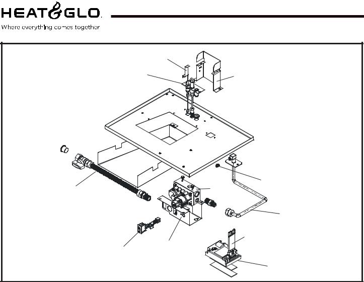
Service Parts |
6000TV-OAK, 6000TV-OAK-IPI |
|
|
|
|
(NG, LP) Exploded Parts Diagram |
Beginning Manufacturing Date: 4-01 |
|
|
Ending Manufacturing Date: ______ |
|
3 2
4
12 |
5 |
1 13
6 Log Set Assembly
9 |
7 |
|
8 |
10 |
11 |
Part number list on following page.
4 |
Heat & Glo • 6000TV-OAK, 6000TV-OAK-IPI • 384-900 Rev. N • 11/05 |
Service Parts List |
6000TV-OAK, 6000TV-OAK-IPI |
IMPORTANT: THIS IS DATED INFORMATION. The most current information is located on your dealers VIP site. When ordering, supply serial and model numbers to ensure correct service parts.
ITEM |
COMMON PARTS |
|
SERIAL # |
PART NUMBER |
|
|
|
|
|
|
|
1 |
Burner NG, LP |
|
|
SRV383-338A |
|
|
|
|
|
|
|
2 |
Glass Door Assembly |
|
|
GLA-6TROC |
|
|
|
|
|
|
|
3 |
Surround |
PRE |
002324021 |
385-130 |
|
POST 002324021 |
2026-108 |
||||
|
|
||||
4 |
Hood |
|
|
SRV60-143-BK |
|
|
|
|
|
|
|
5 |
Log Grate |
|
|
383-360A |
|
|
|
|
|
|
|
6 |
Oak Log Set Assembly |
|
|
LOGS-6OAK |
|
|
|
|
|
|
|
7 |
Log 1 |
|
|
SRV385-720 |
|
|
|
|
|
|
|
8 |
Log 2 |
|
|
SRV385-724 |
|
|
|
|
|
|
|
9 |
Log 3 |
|
|
SRV385-721 |
|
|
|
|
|
|
|
10 |
Log 4 |
|
|
SRV385-723 |
|
|
|
|
|
|
|
11 |
Log 5 |
|
|
SRV385-722 |
|
|
|
|
|
|
|
12 |
Combustion Board |
|
|
385-401 |
|
|
|
|
|
|
|
|
Touch Up Paint |
|
|
TUP-GBK-12 |
|
|
|
|
|
|
|
|
Glass Latch Assembly |
|
|
386-122A |
|
|
|
|
|
|
|
|
Mineral Wool Embers |
|
|
050-721 |
|
|
|
|
|
|
|
|
Vermiculite Embers |
|
|
MYSTIC-EMBERS |
|
|
|
|
|
|
|
|
High Temp Limit Switch |
|
|
066-531 |
|
|
|
|
|
|
|
|
Pilot Orifice NG |
|
|
446-505 |
|
|
|
|
|
|
|
|
Pilot Orifice LP |
|
|
446-517 |
|
|
|
|
|
|
|
|
STANDING PILOT IGNITION ONLY |
|
|
|
|
13 |
Junction Box |
PRE |
002324021 |
100-250A |
|
POST 002324021 |
4021-013 |
||||
|
|
||||
|
Thermocouple |
|
|
446-511 |
|
|
|
|
|
|
|
|
Thermopile |
|
|
060-512 |
|
|
|
|
|
|
|
|
Conversion Kit NG |
|
|
NGK-6TVOC |
|
|
|
|
|
|
|
|
Conversion Kit LP |
|
|
LPK-6TVOC |
|
|
|
|
|
|
|
|
INTERMITTENT PILOT IGNITION (IPI) ONLY |
|
|
|
|
13 |
Junction Box |
PRE |
002324021 |
383-250A |
|
POST 002324021 |
4021-013 |
||||
|
|
||||
|
Conversion Kit LP |
|
|
LPK-6TVOC-IPI |
|
|
|
|
|
|
|
|
ACCESSORIES |
|
|
|
|
|
Trim Door Mesh |
|
|
MESH-6000 |
|
|
|
|
|
|
|
|
Fan Kit |
|
|
GFK-160A |
|
|
|
|
|
|
|
|
Wall Switch Kit, Off-white |
|
|
WSK-21 |
|
|
|
|
|
|
|
|
Wall Switch Kit, White |
|
|
WSK-21-W |
|
|
|
|
|
|
|
Heat & Glo • 6000TV-OAK, 6000TV-OAK-IPI • 384-900 Rev. N • 11/05 |
5 |
|
Service Parts |
6000TV-OAK-IPI |
|
(NG, LP) Exploded Parts Diagram |
Beginning Manufacturing Date: 4-01 |
|
|
Ending Manufacturing Date: ______ |
Intermittent Pilot Ignition |
11 |
|
Valve Assembly |
8 |
9 |
|
7
1 |
3 |
4
6
2 10
5
ITEM |
|
DESCRIPTION |
|
SERIAL # |
PART NO. |
1 |
Flex Ball Valve Assembly |
|
|
|
302-320A |
2 |
ON/OFF Rocker Switch |
|
|
|
060-521A |
|
|
|
|
|
|
3 |
Valve NG |
|
|
|
750-500 |
|
|
|
|
|
|
3 |
Valve LP |
|
|
|
750-501 |
|
|
|
|
|
|
4 |
Flexible Gas Connector |
|
PRE |
002324021 |
477-301A |
|
POST 002324021 |
383-302A |
|||
|
|
|
|||
5 |
Module |
|
|
|
593-592 |
6 |
Wire Assembly |
|
|
|
593-590A |
7 |
Burner Orifice NG (#40C) |
|
|
|
582-840 |
Burner Orifice LP (#53C) |
|
|
|
582-853 |
|
|
|
|
|
||
8 |
Pilot Assembly NG |
|
PRE |
002324021 |
385-510A |
|
POST 002324021 |
4021-025 |
|||
|
|
|
|||
8 |
Pilot Assembly LP |
|
PRE |
002324021 |
385-511A |
|
POST 002324021 |
4021-026 |
|||
|
|
|
|||
9 |
Pilot Bracket |
|
|
|
385-164 |
|
|
|
|
|
|
10 |
Valve Bracket |
|
PRE |
002324021 |
550-169 |
|
POST 002324021 |
2025-101 |
|||
|
|
|
|||
11 |
Ground Strap |
|
|
|
2025-512 |
|
3V Adaptor Plug |
|
|
|
593-593A |
|
Battery Pack |
|
|
|
593-594A |
|
72" & 80" Wire Assembly |
|
|
|
522-504A |
6 |
Heat & Glo • 6000TV-OAK, 6000TV-OAK-IPI • 384-900 Rev. N • 11/05 |
 Loading...