


WSK-MLT MULTIFUNCTION WALL SWITCH
- INSTALLATION AND OPERATING INSTRUCTIONS -
Introduction
The WSK-MLT multifunctional wall switch is designed to control flame height, blower speed, and auxiliary functions on your gas fireplace. For models equipped with the Intellifire system (IPI), the cold climate function can control the pilot flame as well. The wall switch is equipped with thermostat functions which can automatically control the temperature in the room in which it is installed. The wall switch interfaces with both intermittent and standing pilot systems. An auxiliary function provides 110-120 VAC source for added features the fireplace may have installed. Electrical ratings for the control box are 110 VAC, 60 Hz, and is required for operation of this device.
Installation precautions
This remote is tested and safe when installed in accordance with this installation manual. It is your responsibility to read all instructions before starting installation and to follow these instructions carefully during installation. Do not install any components that may be damaged. Do not modify, disassemble, or substitute any of the components included with this kit. Installation of this unit must be done by a qualified service technician.
WALL SWITCH |
CONTROL |
WIRE |
|
FLAME |
|
SOLENOID |
COVER |
|
|
|
PLATE |
CONTROL |
|
BOX |
|
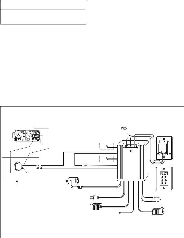
Figure 1. |
|
1.0 Installation instructions
Placement of this wall switch may affect performance or accuracy of the automatic (thermostat) control. An assessment of the space should be done prior to installation for optimal performance. See the installation instructions section I for recommendations.
NOTE: The electrical junction box provided with the fireplace must be wired with 110 VAC before installing this kit. See owners manual for details.
All wiring should be done by a qualified electrician and shall be in compliance with local codes and with the National Electric Code ANSI/NFGA No. 70current (in the United States), or with the current CSA C22.1 CANADIAN ELECTRIC CODE (in Canada).
 WARNING
Shock Hazard
Do not provide any power to this unit until all wiring is completed. Failure to do so may destroy parts of this device and render it unusable, and may lead to possible electrical shock.
Fire Hazard
Modification of any parts or installation of damaged components will void the warranty, and you may possibly cause a fire hazard.
1.1 Determine location
Determine the location for the wall switch. The chosen location should provide an accessible location in the same space as the gas fireplace. Never place this unit in a separate room. The control wire supplied with this switch is 33 ft (10M) in length. The distance from the fireplace to the switch may be lengthened provided that the wire used never exceeds 50 ft, and that the distance from the fireplace to the switch never exceeds 30 ft.
The switch should be mounted into a listed electrical junction box. The junction box should be dedicated to this wall switch. Never install this wall switch into a junction box that is shared with other electrical service or devices. If possible, install this unit on an interior wall of the residence at a recommended height of 5 ft from the flooring. Should the switch be installed on an exterior wall, be certain wall insulation is kept intact and not damaged or dislodged during the installation of the electrical junction box.
For exterior wall installations, it is recommended that the junction box be sealed with caulking material. This will minimize heat loss through this location and improve the accuracy of the automatic (thermostat) operation.
Copyright 2007
Hearth & Home Technologies Inc.
20802 Kensington Blvd., Lakeville, MN 55044
1 |
130-911G 12/07 |

1.2 Wiring the wall switch
Once a location is chosen and the electrical box is installed proceed as follows. Install the provided control wire from the fireplace to the switch location. (Control wire for Heatilator products is supplied with the fireplace). Use caution not to stress the wire around tight or sharp corners. Do not run the control wire adjacent to existing or future phone, data, cable, or electrical lines. The wire should not come into contact with any part of the fireplace exterior with the exception of where it exits the outer wrap. Feed the wire
to the electrical junction box and through a provided or approved strain relief. Using a screw driver, connect the red wire to the “R” terminal, the yellow or white wire to the “W” or “Y” terminal, and the green wire to the “G” terminal. Do not over-tighten. Using the screws provided, mount the switch to the electrical junction box right side up. Install provided cover plate using the screws provided. Do not use a substitute cover even though it may fit. The provided one is specifically designed for the automatic (thermostat)
function of the unit.
For units WITH factory installed Rocker Switch
WIRES WITH LABEL "FOR USE WITH WALL SWITCH ONLY"
(LOCATED UNDER FIREPLACE)
VALVE
NOT
USED
BROWN
BROWN
NOT
USED
RED
RED
FLAME
SOLENOID
FLAME HIGH/LOW
AC
PLUG
YELLOW OR |
|
RED |
WHITE |
|
REAR VIEW |
|
|
|
|
|
GREEN |
RED |
|
|
BLACK |
G W*R |
R W* G |
RED
BLACK
FRONT VIEW
ORANGE
ORANGE |
|
|
BLACK |
YELLOW |
FACTORY |
|
|
|
|
YELLOW |
CONNECTED |
|
TOGETHER |
|
|
|
*May be labeled as “W” or “Y”. |
AUX |
BLACK |
FAN THERMOSTAT |
|
|||
|
CONNECTION |
|
|
Figure 2. Standing Pilot Wiring Diagram
GROUND PIGTAIL |
FAN |
|
CONNECTION |
||
GREEN |
||
|
For units WITH factory installed Rocker Switch
WIRES WITH LABEL "FOR USE WITH WALL SWITCH
ONLY" (LOCATED UNDER FIREPLACE)
BATTERIES
|
|
GREEN |
BROWN |
|
BLACK |
RED |
YELLOW |
ORANGE |
|
|
|
or |
|||
|
|
|
|
|
|
WHITE |
|
|
GROUND |
|
|
|
BLACK |
RED |
|
IPI |
BLACK |
|
|
|
|
||
|
|
|
|
|
|||
VALVE |
|
|
|
|
|
|
|
|
|
|
1 |
|
|
|
G W* R |
|
|
IPI |
2 |
|
|
|
|
|
|
3 |
|
BROWN |
|
||
|
|
MODULE |
4 |
|
BROWN |
|
|
|
|
5 |
|
|
|||
|
|
|
6 |
|
RED |
|
|
|
|
|
7 |
|
|
||
|
|
|
8 |
3V DC |
|
|
|
FLAME |
RED (FEMALE/MALE) |
|
|
BLACK |
|
||
RED (MALE/FEMALE) |
|
|
|
||||
SOLENOID |
|
|
|
|
|
||
|
|
|
|
|
|
|
|
|
|
FLAME ON |
RED |
|
|
|
|
|
|
|
RED |
|
|
|
|
|
|
|
|
|
ORANGE |
|
|
|
|
FLAME HIGH/LOW |
AC |
|
|
ORANGE |
|
ADAPTER WIRES |
|
|
|
|
|
|
|
|
|
PLUG |
|
BLACK |
|
|
|
*May be labeled as “W” or “Y”. |
|
AUX |
|
BLACK |
|
||
|
|
CONNECTION |
|
GROUND |
|
||
|
|
|
|
|
|
||
Figure 3. Intellifire (IPI) Wiring Diagram |
|
|
|
PIGTAIL |
|
||
|
|
|
GREEN |
|
|||
RED
REAR VIEW
GREEN
G
W*
R
FRONT VIEW
YELLOW FACTORY
YELLOW CONNECTED TOGETHER
FAN THERMOSTAT
FAN
CONNECTION
BLACK
2
1.3 Installing the control box
 CAUTION
•Do NOT install the control box when fireplace is hot.
•Do NOT plug control box in until all connections are complete.
1.Place control box into the base pan area of the fireplace. Place unit as close to the louvers or decorative front as possible and to either the left or right side.
2.Connect the red, yellow or white, and green wires to the appropriate labeled terminals on the control box.
For units WITH factory installed rocker switch.
3.Find the red and brown pigtail wire (labeled “ FOR USE WITH REMOTE OR WALL SWITCH ONLY”) which are attached to the fireplace ON/OFF rocker switch.
Standing Pilot Ignition: Connect these wires with the red and brown wires extending from control box (Fig 2).
Intellifire (IPI): Connect these wires with the brown wires extending from the control box (see Figure 3).
For units WITHOUT factory installed rocker switch.
Standing Pilot Ignition:
Find these parts packed with WSK-MLT:
•Rocker switch
•Rocker switch bracket
•Strips of Velcro
•Black and white wire pigtails - (2)
•Female ends (only used on Standing Pilot applications) - (2)
Cut male ends off black wires on each pigtail. Strip each end of wire approximately 1/4 inch. Slide each stripped wire into a female end and crimp. Slide rocker switch into bracket until it snaps into place. Attach end of each pigtail to each side of rocker switch. Find the top (brown) and bottom (red) wires from the control box and attach to white wires from rocker switch. Attach one black wire to the TH/TP side of gas valve and the other to the TH side of the gas valve. Attach the Velcro to the bottom of the rocker switch bracket and mount in a convenient location next to gas valve. (Refer to Figure 4).
For units WITHOUT factory installed Rocker Switch
VALVE BLACK
To
Thermopile
WHITE
WHITE
BLACK
SWITCH AND WIRE
ASSEMBLY SUPPLIED
WITH WSK-MLT
* May be labeled as “W” or “Y”.
|
|
YELLOW |
|
|
WHITE |
NOT |
RED |
|
USED |
BLACK |
G W* R |
|
BROWN |
|
|
BROWN |
|
NOT |
RED |
|
USED |
BLACK |
|
RED
RED
FLAME
SOLENOID
|
|
ORANGE |
FLAME HIGH/LOW |
ORANGE |
|
AC PLUG |
BLACK |
|
|
|
|
AUX |
|
BLACK |
CONNECTION
GROUND PIGTAIL
GREEN
RED
REAR VIEW
GREEN
G
W*
R
FRONT VIEW
YELLOW FACTORY
CONNECTED
YELLOW TOGETHER
FAN THERMOSTAT |
|
|
FAN |
BLACK |
CONNECTION |
|
Figure 4. Standing Pilot Wiring Diagram
3
 Loading...