


|
1050 Fountain St. N. |
Cambridge, Ontario, Canada N3H 4R7 |
|
Bus. (519) 650-5501 |
Fax (519) 650-3773 |
Toll Free Phone 1-800-361-1517 |
|
Toll Free Fax 1-800-327-5609 |
|
INSTALLATION
AND
OPERATING INSTRUCTIONS
Save these instructions for future use
Note: Please read these instructions thoroughly before attempting to install this unit.
Model 9100
Model  7100
7100
WARNING: Improper installation, adjustment, alteration, service or maintenance can cause injury or property damage. Refer to this manual. For assistance or additional information, consult a qualified installer, service agency, manufacturer (dealer) or the gas supplier.
Note: This appliance can only be installed in the state of Massachusetts by a Massachusetts licensed plumber or gasfitter.
The oven door thermometer does not sense temperature. It is for aesthestics only and is nonfunctional.

 ®
®
CERTIFIED
C US
These symbols on the nameplate mean the product has been design certified by American Gas Association Laboratories and Canadian Gas Association Laboratories.
Manual #7715
REV 111204
MODEL 9100/7100 GAS RANGE
ATTENTION INSTALLER: Leave this manual with appliance
© 2004 HEARTLAND APPLIANCES INC.

Gas Models 9100/7100
CONSUMER WARRANTY
ENTIRE PRODUCT – LIMITED ONE YEAR WARRANTY
HEARTLAND warrants the replacement or repair of all parts, including gas components of this Cookstove which prove to be defective in material or workmanship, with the exception of the painted or porcelain enamel finish or plated surfaces, for one year from the date of original purchase. Such parts will be repaired or replaced at the option of Heartland without charge, subject to the terms and conditions set out below.
The warranty period against defects in the painted or porcelain enamel finish, or plated surfaces, is 90 days from date of original purchase. The warranty does not include replacement of oven lamps or charcoal filters.
TERMS AND CONDITIONS
1.This warranty applies only for single family domestic use when the Cookstove has been properly installed according to the instructions supplied by Heartland and is connected to an adequate and proper utility service. Damage due to faulty installation, improper usage and care, abuse, accident, fire, flood, acts of God, commercial, business or rental use, and alteration, or the removal or defacing of the serial plate, cancels all obligations of this warranty. Service during this warranty must be performed by a factory Authorized Service Person.
2.Warranty applies to product only in the country in which it was purchased.
3.Heartland is not liable for any claims or damages resulting from any failure of the Cookstove or from service delays beyond their reasonable control.
4.To obtain warranty service, the original purchaser must present the original Bill of Sale, Model and Serial number. Components repaired or replaced are warranted through the remainder of the original warranty period only.
5.The warranty does not cover expense involved in making this appliance readily accessible for servicing.
6.This warranty gives you specific legal rights. Additional warranty rights may be provided by law in some areas.
7.Adjustments such as calibrations, levelling, tightening of fasteners, or utility connections normally associated with original installation are the responsibility of the dealer or installer and not that of the Company.
TO ENSURE PROMPT WARRANTY SERVICE, SEND IN YOUR WARRANTY CARD WITHIN 10 DAYS OF PURCHASE.
If further help is needed concerning this warranty, contact:
Customer Service |
Business (519) 650-5775 |
Heartland Appliances Inc. |
Fax (519)650-3773 |
1050 Fountain St. N. |
Toll Free Telephone 1-800-361-1517 |
Cambridge, Ontario, |
Toll Free Fax 1-800-327-5609 |
Canada N3H 4R7 |
|
PLACE OF PURCHASE______________________________
DATEOFPURCHASE_______________________________
SERIALNUMBER__________________________________
MODELNUMBER__________________________________
To move range for service or cleaning
WARNING
Range body rests on base.
When moving, move by base only.
1.Disconnect electrical power.
2.Place temporary floor protection in front of range.
3.Slide out from wall and place floor protection under front legs and slowly pull out to gain access to rear.
4.To reinstall, reverse these instructions.
The use of a gas cooking appliance results in the production!of heat and moisture in the room in which it is installed. Ensure that the kitchen is well ventilated: keep natural ventilation holes open or install a mechanical device (mechanical extractor hood)
Prolonged intensive use of the appliance may call for additional ventilation, for example opening of a window, or more effective ventilation, for example increasing the level of mechanical ventilation where present.
—FOR YOUR SAFETY—
DO NOT STORE OR USE GASOLINE OR OTHER FLAMMABLE VAPOURS OR LIQUIDS IN THE VICINITY OF THIS APPLIANCE.
*Do not use the range as a heater.
*Do not heat unopened glass or metal containers in the oven.
*Grease accumulation is the cause of many cooking fires. Clean the oven and broiler compartment regularly.
*Do not attempt to extinguish a grease fire with water. Cover grease fires with a pot lid or baking soda.
*Avoid the use of aerosol containers near the range.
*Never place pans, cookie sheets or roasters directly on the oven bottom -use the rack in its lowest position.
*Do not cover the entire bottom of the oven with aluminium foil. Allow at least 1" of space all around pots, pans or cookie sheets in the oven to permit convection air flow.
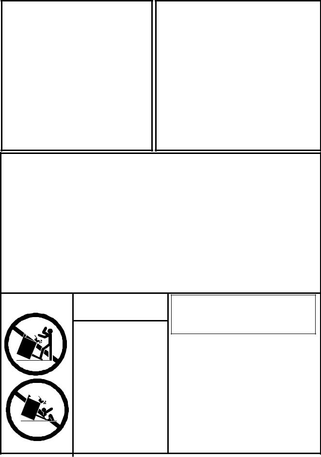
WARNING
•ALL RANGES CAN
TIP
•INJURY TO PERSONS COULD RESULT
•SEE INSTALLATION INSTRUCTIONS
WARNING: If the information in this manual is not followed exactly, a fire or explosion may result causing property damage, personal injury or death.
Do not store or use gasoline or other flammable vapours and liquids in the vicinity of this or any other appliance.
WHAT TO DO IF YOU SMELL GAS
•Do not try to light any appliance.
•Do not touch any electrical switch; do not use any phone in your building.
•Immediately call your gas supplier from a neighbour’s phone. Follow the gas supplier’s instructions.
•If you cannot reach your gas supplier, call the fire department.
Installation and service must be performed by a qualified installer, service agency or the gas supplier.

TABLE OF CONTENTS
1. |
Assembly and Installation .................................. |
2 |
29. Care and Cleaning ............................................ |
18 |
|
2. |
Assembly of Range Base ...................................... |
2 |
30. Porcelain ............................................................. |
18 |
|
3. |
Assembly of Range Body to Base ......................... |
3 |
31. Oven Cleaning ..................................................... |
19 |
|
4. Assembly of Exhaust Hood to Range ....................... |
4 |
32. Surface Burners ................................................... |
19 |
||
5. |
Positioning the Range ........................................... |
4 |
33. Nickel Trim .......................................................... |
20 |
|
6. |
Installation Clearances .......................................... |
5 |
34. Exhaust Hood ...................................................... |
20 |
|
7. |
Electrical and Gas Installation ............................... |
6 |
35. Oven and Cabinet Light ....................................... |
20 |
|
8. |
Exhaust Hood ...................................................... |
7 |
36. Interior Oven Rack Removal ................................. |
21 |
|
9. |
Ventless Installation .............................................. |
7 |
37. Rack Supports Removal ..................................... |
21 |
|
10. Vented Installation ................................................ |
7 |
38. Oven Door Removal ............................................. |
22 |
||
11. Installation of Ducting ............................................. |
8 |
39. |
Broiling................................................................ |
23 |
|
12. Venting Safety Guidelines .................................... |
9 |
40. |
Broiling Pan......................................................... |
23 |
|
13.Gas Line Installation ................................................ |
9 |
41. |
Oven Light............................................................ |
23 |
|
14. Important Safety Instructions ........................... |
10 |
42. Broiler Drawer Removal ....................................... |
24 |
||
15. Exhaust Hood Safety ........................................... |
10 |
43. |
Setup and Trouble Shooting ........................... |
25 |
|
16. Features ............................................................. |
11 |
44. Burner Setup and Adjustment ............................. |
25 |
||
17. Sealed Burner Features ....................................... |
11 |
45. Range Problem Solver ......................................... |
25 |
||
18. Oven Features ..................................................... |
12 |
46. Air Shutter Adjustment ........................................ |
26 |
||
19. Other Features ................................................... |
12 |
47. |
Oven Burner Assembly....................................... |
26 |
|
20. Control Panel Layout .......................................... |
13 |
48. Trouble Shooting Guide ....................................... |
27 |
||
21. Operation ........................................................... |
14 |
49. |
Conversion Kits and Information................... |
28 |
|
22. Top Burner Operation ........................................... |
14 |
50. Products ............................................................ |
29 |
||
23 Oven Lighting...................................................... |
15 |
51. Products ............................................................. |
31 |
||
24.Range Thermostat................................................. |
15 |
52. Parts Diagram ................................................... |
32 |
||
25 Power Failure Operation ....................................... |
16 |
53. Parts List ............................................................ |
33 |
||
26. Manually Lighting the Top Burners....................... |
16 |
54.RatingPlate......................................................... |
34 |
||
27. Manually Lighting the Oven Burner......................... |
16 |
55. |
Wiring Diagrams ............................................... |
35 |
|
28. Clock/Timer.......................................................... |
17 |
|
|
|
|
1
Assembly and Installation
To fully enjoy your new range, it is important that you read this booklet thoroughly.
Note: Please check for any damage that may have occurred during shipping. In the unlikely event that you find any shipping damage, inform your dealer immediately!
The Model 7100 and 9100 Range consists of three main parts:
The Range Base
The Range Body, and
The Exhaust Hood or Cresting Assembly
1/8"- 1/4"
Tools required for assembly:
Slot screw driver 7/16” (11 mm) wrench or crescent wrench
5/16" (8 mm) wrench or crescent wrench
(You must have a qualified gas technician install this appliance to be sure |
Teflon Glider |
the installation codes and rules are observed.) |
|
Teflon |
Figure 1a |
Glider |
Painted section
Nickel plated section
Figure 1
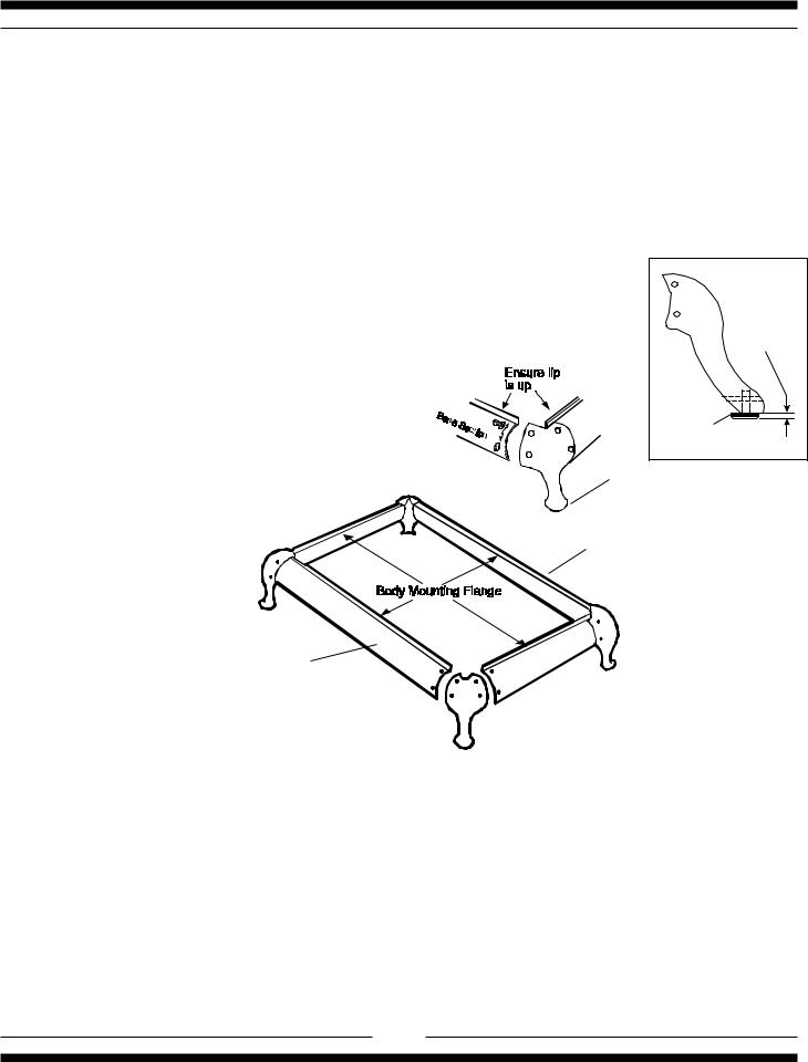
Assembly of Range Base
1.Unpackage the base sections, legs and hardware package which are located in a carton fastened to the skid at rear of the range (it would be a good idea to check for any damage that may have occurred during shipping).
2.Screw the base levelling bolts (with teflon glider attached) into each of the four legs. The levelling bolts are located in the hardware package. When installing the levelling bolts, the teflon glider should extend beyond the bottom of the leg by approximately 1/8"-1/4". Adjusting levelling bolts in too far will cause the leg to drag on the floor potentially causing damage to flooring. (see figure 1a ) . Check that gliders and floor are free of any debris, this will ensure you do not scratch your floor.
3.Assemble base to legs using the nuts and bolts provided. For the 48" the shorter base sections are the sides and the longer sections are front and rear. (the black painted section goes to the rear, see fig. 1). For the 30" the base sections are all the same length, the black painted section goes to the rear, see fig. 1.
4.Hand tighten the nuts and bolts until the range base is completely assembled. Ensure that all base sections are installed with the lip up.
5.Adjust base sections to the most upper position and tighten up the nuts and bolts.
2
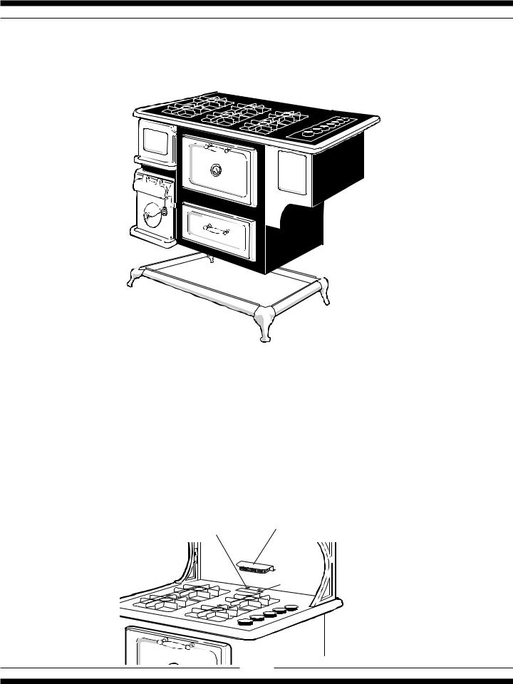
Assembly of Range Body to Base
Lift the range at the front and rear, do not lift by nickel trim.
1.The range body rests directly on the base - no bolts are required. Two people are needed to lift it on to the base.
2.In order not to damage the nickel trim or enamel finish, lift the range from the front and the rear . The person at the front can first remove the oven door and use the oven opening for a hand hold. The rear of the oven body at the bottom can be used to lift from the back.
3.Lift the range off pallet and onto base, making sure the range is sitting square and level on base. The stove sits over the lip of the base assembly. Helpful hint: Instead of trying to square the entire stove over the base, put one side or back on first then slowly lower the other side into position.
4.Lastly, install the oven vent deflector on the top of the cooking surface over the oven vent. Loosen the two screws enough to slip the oven vent under the screws , and tighten up the screws. (see illustration below)
Oven vent deflector
Loosen two screws
Oven vent |
3 |
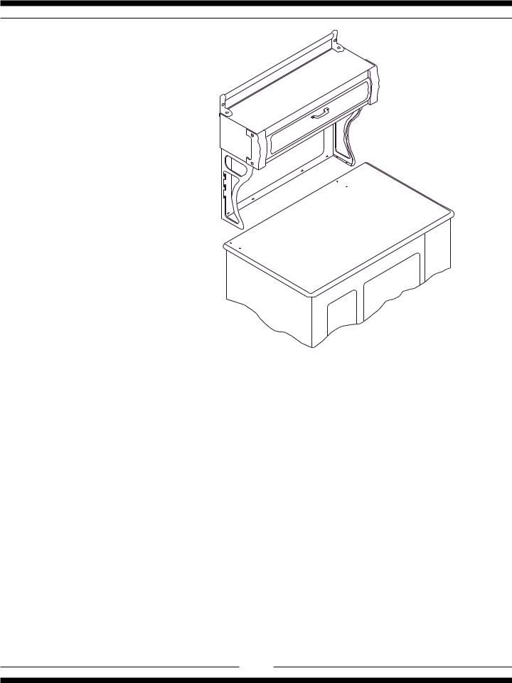
Assembly of Exhaust Hood to
Range
Seethemanualentitled"Cabinet Assembly
Instructions for Gas , Electric ,Combination and Wood Stoves" which is included with the cabinet .
Positioning the Range
1.When the range is fully assembled, recheck all electrical connections especially between the exhaust hood and the back of the range. As well, check that all nuts and bolts have been tightened.
2.Ensure teflon gliders and flooring are clean, (as described in the second paragraph under
"Assembly of Range Base".)
3.Caution: On flooring with very rough surfaces or deep, large grooves the appliance may have to be lifted and slowly slid into position.
4.Put both hands on the trim and carefully push the range into place, make sure floor is clear of all debris. Don't forget to plug in the main power cord and the exhaust hood power cable before the range is in its final position. See cabinet installation instructions.
5.To level the range, simply adjust the levelling screws with teflon pads located at the bottom of each leg (the ones you assembled in step 2 of "Assembly of Range Base"). Using a 5/16 (8 mm) openend wrench turn the adjusting screw clockwise to raise up the corner, and counter-clockwise to lower thecorner.(Don'tforgettheteflonglidershouldextend beyondthebottomofthelegbyapproximately 1/8"-1/4")
6.Note: On soft kitchen flooring, the weight of the stove may cause slight depressions in the flooring.
When the range is in position and levelled, you may want to place coasters under the teflon gliders of each leg, to protect the floor. Remove the coasters when moving the range for cleaning or servicing.
4
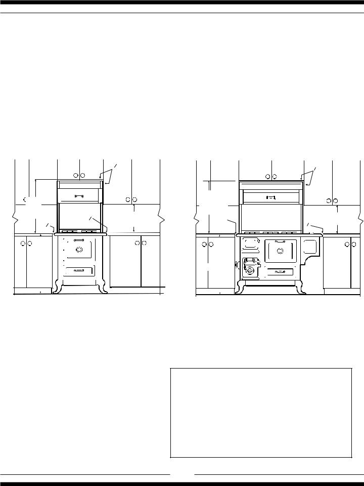
Installation Clearances
If the range must stand beside a refrigerator, it is important for proper air circulation, that there be at least 5" of space between the two appliances.
Do not install range closer than 1/2" from adjacent surfaces.
To eliminate the risk of burns or fire by reaching over heated surface units, installation of cabinet storage space above the surface units should be avoided. If there is existing cabinet storage space have at least 30" of clearance. (see fig 3)
For best cooking results, your range should be level. This can be checked with a carpenter’s level on top of the cooking surface and across the oven rack. If levelling is required, adjust the leveller screws under one or more of the legs (see "Positioning the Range" step 4).
0 |
0 |
|
min |
|
|
min |
|
|
|
|
|
30 1/4" |
|
|
||
30 1/4" |
|
min 18" |
768 mm |
|
min 18" |
|
768 mm |
0 |
1" |
|
|||
0 |
457 mm |
0 |
457 mm |
|||
|
25 mm |
|||||
|
|
|
|
|
|
|
|
|
|
|
|
|
|
|
|
|
|
|
|
|
|
|
|
|
|
|
|
|
|
|
|
|
|
|
|
|
|
|
|
|
|
|
|
|
|
|
|
|
|
|
|
|
|
|
|
|
|
|
|
|
|
|
|
|
max |
|
|
|
|
min |
|
||||||||||||||||||||||||
|
|
|
|
|
|
|
|
36 " |
|
|
|
|
|
|
|
|
|
|
|
|
|
|||||||||
36 " |
|
|
|
|
|
|
|
|
|
|
|
|
|
|
|
|
|
|
|
|
|
|
|
|
||||||
|
|
|
|
|
|
|
|
|
|
|
|
|
|
|
|
|
|
|
|
|
|
|
|
|||||||
|
|
|
|
|
|
|
|
|
|
|
914 mm |
|
|
|
|
|
|
|
|
|
||||||||||
914 mm |
|
|
|
|
|
|
|
|
|
|
|
|
|
|
|
|
|
|||||||||||||
|
|
|
|
|
|
|
|
|
|
|
|
|
|
|
|
|
||||||||||||||
|
|
|
|
|
|
|
|
|
|
|
|
|
|
|
|
|
|
|
|
|
|
|||||||||
|
|
|
|
|
|
|
|
|
|
|
|
|
|
|
|
|
|
|
|
|
|
|
|
|
|
|
|
|
|
|
|
|
|
|
|
|
|
|
|
|
|
|
|
|
|
|
|
|
|
|
|
|
|
|
|||||||
|
|
|
|
|
|
|
|
|
|
|
|
|
|
|
|
|
|
|
|
|
|
|
|
|
|
|
|
|
|
|
|
|
|
|
|
|
|
|
|
|
|
|
|
|
|
|
|
|
|
|
|
|
|
|
|
|
|
|
|
|
|
|
Model 9100 Installation Clearance |
|
|
Model 7100 Installation Clearance |
||||||||||||||||||||||||||
Fig 3 Installation Clearances
The clearances in the table are also stated on the rating plate and on a reproduction of the plate on the back page of this manual. (see "installation clearances" diagram Fig. 3)
Installation Clearances
Surface adjacent to cook top-left (7100) .............. |
1” (25mm) |
Surface adjacent to cook top-right (7100) ............ |
0” (0 mm) |
Surface adjacent to cook top (9100) .................... |
0” (0 mm) |
Surface adjacent to warming oven ........................ |
0” (0 mm) |
Cook top to underside of adjacent cabinets ... 18” (457 mm)
Cook top to underside of cabinets ............. |
30 1/4” (768 mm) |
Maximum depth of overhead cabinets ............ |
13” (330 mm) |
Maximum depth of counters .......................... |
24” (610 mm) |
Maximum height of counters .......................... |
36” (914 mm) |
Rear clearance ..................................................... |
0” (0 mm) |
5

Electrical Installation
THE MODEL 7100/9100 GAS RANGE MUST BE ELECTRICALLY GROUNDED IN COMPLIANCE WITH LOCAL CODES AND IN THE ABSENCE OF LOCAL CODES, WITH THE NATIONAL ELECTRICAL CODE ANSI/NFPA 70 “LATEST EDITION” IN THE U.S. OR THE CANADIAN ELECTRICAL CODE, PART I, CSA STANDARD C22.1 IN CANADA or YOUR NATIONAL ELECTRICAL CODE
Connect the female end of the power cord to the main power (male) receptacle at the rear of the stove. See page 8 for receptacle locations and figure 4 for receptacle illustration
This range must be plugged into a properly grounded/earth, receptacle. The grounding/earth prong must not be removed, from the plug. DISCONNECT THE ELECTRICAL SUPPLY BEFORE SERVICING THE APPLIANCE.
The receptacle to be used for this appliance must be wired to STANDARD WIRING PRACTICES.
female end of male receptacle the power cord
Main power hook-up Figure 4
Exhaust Hood Electrical Connection
After your exhaust hood has been installed the very last thing to do is to connect the special plug to the range. The female receptacle for the exhaust hood is located at the rear of the stove by the main power (male) receptacle (See page 8 for receptacle locations and figure 5 for receptacle illustration). Simply plug the cabinet power cord into the receptacle, be sure to test all functions of the cabinet.
|
male end of the |
female receptacle |
cabinet power cord |
Cabinet power hook-up
Figure 5
6
Exhaust Hood
Your range is equipped with a two speed range hood that may be either vented directly to the outside, or may be installed ventless. A set of exhaust filters are included with your hood. The filters should be cleaned periodically in soapy water. Extras are available from your dealer or directly from Heartland Appliances Inc. Please order 4 or more filters at one time to save freight and handling charges. Phone your dealer for pricing and ordering instructions.
Ventless Installation
Your unit is already set up for ventless operation. Cooking fumes are drawn through the filters and exhausted thru the rear of the hood, back into the room. Install the exhaust filters in their location under the cabinet by first removing the light lens. Then on one side, insert one of the filters into the grooves (front and rear of the cabinet) and slide into place. Repeat these steps for the second filter
Figure 6
Exhaust venting options
Vented Installation, Tools, Material, and Dimensions
Tools required to install vented hood:
Hammer |
Slot screwdriver |
Pliers |
Electric drill |
Measuring tape |
Drill bits |
Sabre saw OR Keyhole saw
Materials Required:
Duct—enough to go through wall or attic to outside. Elbows as required. Roof cap or wall venthood
Caulking to seal around duct Sheet metal screws
The above are standard parts and are available at any hardware store or heating contractor.
7
.
Installation of Ducting
Installation through an outside wall
Remove air deflector (used for ventless operation only). Cut appropriate-sized hole through the wall directly behind the range hood outlet (see Figure 6 ,page 7), making sure no wall studs are cut. Push range into position. From outside of the house, measure distance from the siding to the range outlet. Cut duct pipe that length, plus 1" (25mm) for overlap into outlet. Attach vent hood to pipe. Caulk the back of vent hood and around pipe where it goes through wall and into range hood outlet so caulking seals against outside siding.
Complete installation by following directions under Ventless Installation.
Installation through an attic to an outside wall
If the vent elbows are embedded in the wall, the range may be positioned as shown in Figure 6. Continue the duct through the ceiling into the attic. Terminate duct either on an outside wall just below the sofit using a vent hood or through the roof with a roof cap. Seal with caulking aroundandundercaporhood. Complete your installation by following directions under Ventless Installation.
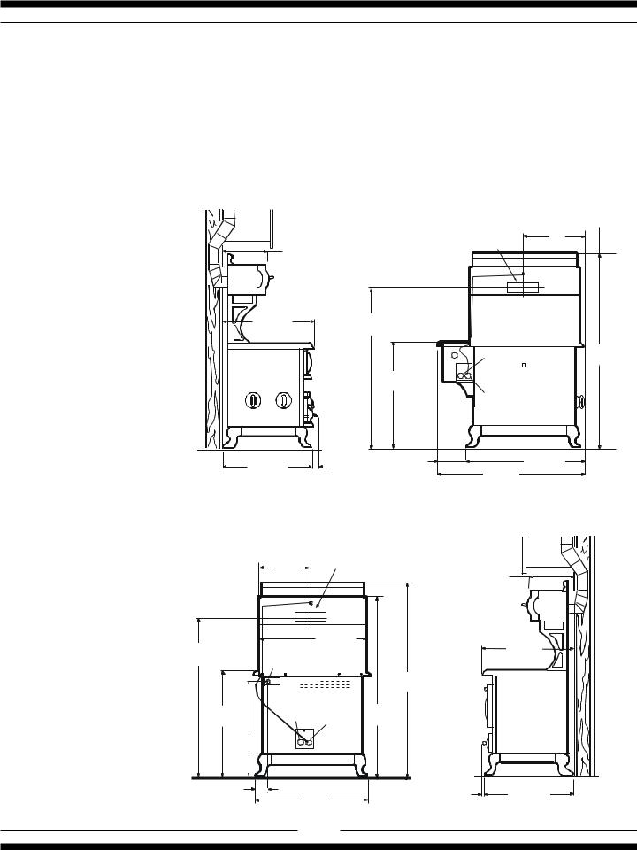
|
R ange Ho od Outlet: |
19" |
|
3 1/4" x 1 0" |
|
14" |
83 m m x 254m m |
483 m m |
356 m m
31. 0" |
|
|
56 " |
|
|
|
|
787 m m |
|
1416 m m |
|
|
|
||
|
|
|
|
|
Power In |
66 1/ 4" |
|
|
|
|
|
|
1682 m m |
||
|
|
|
|
|
(direct c on |
ect) |
|
|
|
|
36 1/8" |
|
8 ft (2.4m ) cord supplied |
||
|
|
|
917 m m |
|
Ex haus t Hood In |
||
|
|
|
|
|
|||
|
|
|
|
|
(female rec epticle) |
||
29 3/4 " |
1 1/4 " |
9 ¼ " |
|
38 1/4" |
|||
235 |
m m |
47 1/2" |
972 m m |
||||
756 mm |
32 |
m m |
|||||
|
|
|
|||||
|
|
|
|
|
1207 m m |
|
|
|
|
|
Model 7100 |
|
|
1 4 7 /8 " |
R ange H ood |
|
|
|
O ut let : 3 1 /4"x 10" |
14. 0" |
||
|
3 7 8 m m |
|
83 m m x 254 m m |
|
|
|
|
|
356 m m |
|
|
2 9 3 /4 " |
|
|
56 " |
|
75 6 m m |
|
31.0" |
|
|
|
787 m m |
|
142 2 m m |
|
|
|
|
G a s In le t-1 /2 N P T |
|
|
||
|
|
|
||
|
|
|
6 6 1 /4 " |
|
|
P ower In |
|
16 8 2 m m |
|
|
(direct connec tion ) |
|
|
|
3 6 1/8 " |
8 ft (2.4m ) cord |
6 2 3 /8 " |
|
|
9 17 m m |
supplied |
E xhaust |
1 5 85 m m |
|
3 4 |
" |
H oo d In |
|
|
|
|
|
||
8 64 m m |
|
|
|
|
3 3 /4" / 92 m m |
29 3 /4" |
2" |
29 3 /4 " |
|
|
51 m m |
756 m m |
||
|
7 5 6 m m |
|||
|
Model 9100 |
|
||
|
|
|
|
|
8
 Loading...