


Installation & Operating Manual
The Harman PB 105 Pellet Boiler
“Ce manuel est disponible en Français sur demande” |
R1 |
SAFETY NOTICE
PLEASE READ THIS ENTIRE MANUAL BEFORE YOU INSTALL AND USE YOUR NEW BOILER. FAILURE TO FOLLOW INSTRUCTIONS MAY RESULT IN PROPERTY DAMAGE, BODILY INJURY, OR EVEN DEATH.
FOR USE IN THE U.S. AND CANADA. SUITABLE FOR INSTALLATION IN MOBILE HOMES
IF THIS HARMAN PELLET BOILER IS NOT PROPERLY INSTALLED,AHOUSE FIRE MAY RESULT. FOR YOUR SAFETY, FOLLOW INSTALLATION DIRECTIONS.
CONTACT LOCAL BUILDING OR FIRE OFFICIALS ABOUT RESTRICTIONS AND INSTALLATION INSPECTION REQUIREMENTS IN YOUR AREA.
CONTACT YOUR LOCAL AUTHORITY (SUCH AS MUNICIPAL BUILDING DEPARTMENT, FIRE DEPARTMENT, FIRE PREVENTION BUREAU, ETC.) TO DETERMINE THE NEED FOR A PERMIT.
CETTE GUIDE D'UTILISATION EST DISPONIBLE EN FRANCAIS. CHEZ VOTRE CONCESSIONNAIRE DE HARMAN STOVE COMPANY.
SAVE THESE INSTRUCTIONS
R4
Tested by

3 |

Table of Contents
|
Assembly |
4 |
|
|
Venting |
8 |
|
|
Installation |
11 |
|
|
Operation |
20 |
|
|
Maintenance |
27 |
|
|
Troubleshooting |
31 |
|
|
Feeder Parts |
32 |
|
|
Specifications |
33 |
|
|
Wiring Diagram |
34 |
|
|
Parts List & Options |
35 |
|
|
Warranty |
36 |
|
|
Testing Label |
37 |
|
|
Quick Reference Start-Up |
Back Cover |
|
|
|
|
|
|
|
|
|
Please read this entire manual before you install and use your new boiler. Failure to follow instructions may result in
property damage, bodily injury, or even death.
SAVE THESE INSTRUCTIONS
Harman Stove Company
352 Mountain House Road
Halifax, PA 17032
4
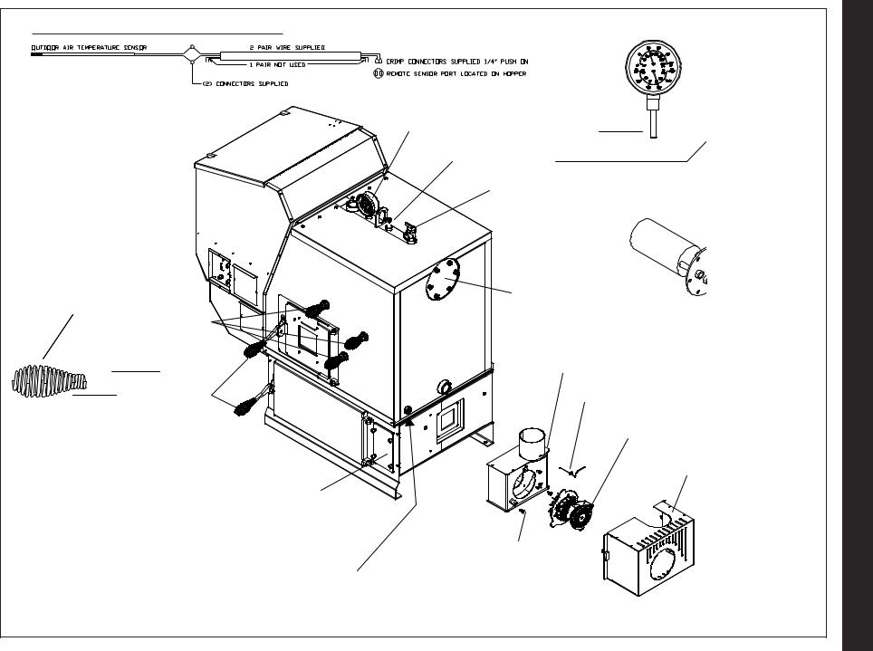
Outdoor Air Temperature Sensor Wiring :
Heat Exchanger
Cleanout Rod Handles
QTY (5)
Firebox & Ash
Door Handles
Access Cover To Secondary Ash Chamber
Remove Cover to access nuts to fasten Flue
Tunnel Weldment to the Ash Chamber.
½”MPT Boiler Drain (Not Shown)
5
Temperature / Pressure Gauge
Aquastat Well
Pressure Relief Valve
Blank Cover*
*Removed w/ Domestic Hot Water Coil Option Shown Her
Flue Tunnel Weldment
ESP Probe
Combustion
H
Thumb Screws (3)
Assembly

Assembly
Boiler Kit Materials: (Refer to pages 4 & 5)
List of items contained within the boiler kit shipped with the unit.
1 - Control board cover
1 - Access cover (Hopper Swing Plate Knob)
5 - Spring Handles
1 - 1/2” Boiler Drain
1 - 3/4” Safety Relief Valve
1 - 1/2” Aquastat Well
1 - 1/2” Dual Temperature/Pressure Gauge
1 - 100ft. Sensor Cable (Outdoor Air Sensor)
1 - Outdoor Air Sensor
1 - Flue Tunnel Weldment
1 - Combustion Blower Assembly
1 - Heat Shield (Comb. Blower)
2 - UY Connectors
2 - Terminals 1/4 Female
1 - #8 X 1/2” TEK
3 - 1/4-20 X 5/8” Wing Screw
4 - 1/4” Lock Washer
4 - 1/4-20 Nuts
6
Installation of the Flue Tunnel Weldment, Combustion Blower and Wiring, ESP and Heat Shield:
Step 1: First install the flue tunnel weldment by aligning the (4) studs up with the (4) holes in the ash chamber base.Fasten the (4) nuts and lock washers provided, to the studs by removing the access cover on the secondary ash chamber.
Step 2: Place the combustion motor onto the flue tunnel weldment and tighten the (3) wing screws provided. Step 3: Insert the Exhaust Sensing Probe (ESP) into the 1/8" hole provided on the flue pipe stub. Fasten with the (1) #8x1/2" TEK screw also provided. ESP will be taped to the sheet metal jacket for shipping purposes.
Step 4: Connect the flex conduit 90 degree elbow(Not Shown) to the heat shield in the hole provided. Then connect the (3) wires from the combustion blower with the (3) wires in the flex conduit by using the push-on connectors and matching the wire colors as follows: Red to Black, White to White and Green to Green. Step 5: Place Heat Shield over combustion blower and align the swell latches with the holes in the sheet metal and tighten.
NOTE: Refer to Fig’s082, 23 and 2448ocated in the
Assembly
After assembly of the flue tunnel weldment, combustion blower assembly with wiring and heat shield, the boiler can now be installed.
1.Install the control board cover as well as the access cover located on the feeder cover.
2.Install the spring handles provided with the unit on the ash door, firebox door and the heat exchanger cleanout rod handles. (Fasten handles by turning them counterclockwise and pushing inward simultaneously).
3.Install 1/2” MPT boiler drain in the fitting as
shown.
Note: Use teflon pipe thread sealant or teflon tape on ALL threads before connections are made.
4.Install 3/4” MPT pressure relief valve as shown.
5.Install the 1/2” MPT aquastat well in fitting as shown, then place aquastat in the well and fasten with a zip tie.
6.Install the 1/2” MPT temperature/pressure gauge in fitting as shown.
7.Locate and install outside air temperature sensor. Location of this sensor should be on the north side of the home or building and out of direct sunlight. Use the cat cable supplied with the boiler to attach sensor to the terminals located on the hopper. (Place at the back side just above and to the right of the main power connection box) The wires can be connected to the sensor with the connectors supplied. Wire nut or butt splice connectors could also be used. The connections at the boiler can be done with the two 1/4” female push on connectors supplied.
8.Fasten conduit to the ash base with the clamps provided.
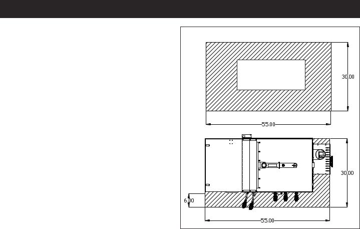
Floor Protection:
The striped area indicates the minimum required floor protection area if the PB105 is going to be placed on a combustible floor. It requires 30” X 55” of non combustible floor protection as shown below. 6” of the floor protection must be in front of the boiler as shown. Flooring must be a minimum of 26 gauge sheet metal. Floor protection must also be provided under any horizontal run of vent pipe equal to the outside diameter of the venting plus 2” to each side.
Example: 4” type “L” or “PL” vent pipe has an outside diameter of 4-1/2” + 2” on each side equals a protected floor area of 8-1/2” wide underneath the horizontal run.
MINIMUM NON-COMBUSTIBLE FLOOR PROTECTIONAREA |
Non-Combustible |
Floor Protector |
Design: |
The first thing that needs to be done is deciding where and how the boiler will be installed.
Things that need to be taken into consideration are the intended use of the boiler for example, is the boiler going to be used as your primary heating system or is it going to be used as a secondary or backup heating system. If it is to be used in conjunction with an existing oil or gas boiler system will it be piped in parallel or in series? The answers to these and other questions can be determined by talking to your certified dealer or a qualified HVAC or plumbing contractor. This will insure that the boiler is installed and piped to accommodate your needs and expectations.
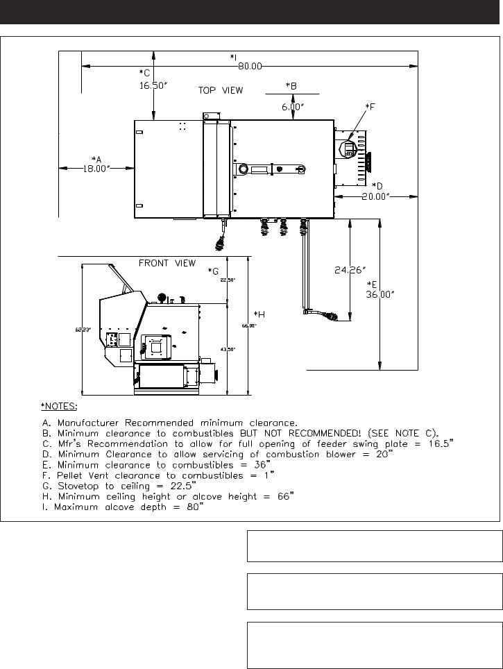
Consideration must be given to the venting as well as electrical and clearance requirements. (Clearances must be maintained to combustibles and also for service)
After the boiler is set into place the venting can be done.
Make sure fans are not used in the fuel storage area, unless they are installed so as not to create a negative pressures in the room where the solid fuel burning appliance is located
7
Assembly |
When installing the PB105 in a mobile home several requirements must be followed:
1.The unit must be bolted to the floor.
2.The unit must be connected to outside air.
3.Floor protection and clearances must be followed.
4.Unit must be grounded to the metal frame of the mobile home.
INSTALLATION IS TO BE PERFORMED BY A QUALIFIEDINSTALLER.
NOTE: All installation clearances and restrictions must be adhered to.
NOTE:Use only 4” diameter type “L” or “PL” venting system. Be sure to inspect and clean exhaust venting system frequently.
8
Venting
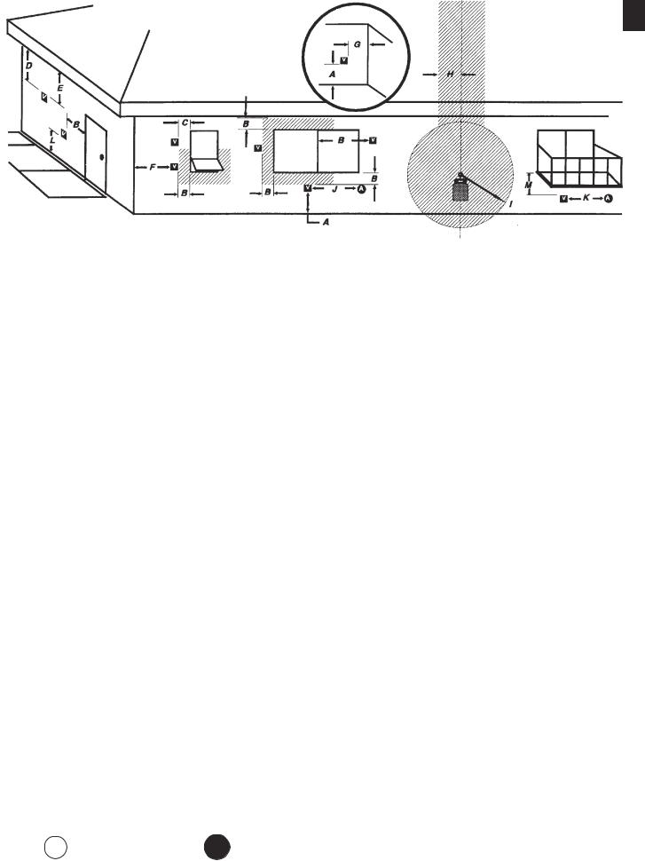
Requirements for Terminating the Venting
WARNING:Venting terminals must not be recessed into a wall or siding.
NOTE: Only PL vent pipe wall pass-throughs and fire stops should be used when venting through combustible materials.
NOTE: Always take into consideration the effect the prevailing wind direction or other wind currents will cause with flyash and /or smoke when placing the termination.
In addition, the following must be observed:
A.The clearance above grade must be a minimum
of 18".1
B.The clearance to a window or door that may be opened must be a minimum of 48" to the side, 48" below the window/door, and 12" above the window/ door.1
( with outside air installed, 18” )
C.A 12" clearance to a permanently closed window is recommended to prevent condensation on the window.
D.The vertical clearance to a ventilated soffit located above the terminal within a horizontal distance of 2 feet (60 cm) from the center-line of the terminal must be a minimum of 18".
E.The clearance to an unventilated soffit must be a minimum of 12".
F.The clearance to an outside corner is 11" from center of pipe.
G.The clearance to an inside corner is 12".
Fixed |
|
Closed |
Openable |
|
|
O p e n a b l e |
|
H.A vent must not be installed within 3 feet (90 cm) above a gas meter/regulator assembly when measured from the horizontal center-line of the regulator.1
I.The clearance to service regulator vent outlet must be a minimum of 6 feet.1
J.The clearance to a non-mechanical air supply inlet to the building or the combustion air inlet to any other appliance must be a minimum of 48”.1
K.The clearance to a mechanical air supply inlet must be a minimum of 10 feet.1
(with outside air installed, 6 feet )
L.The clearance above a paved sidewalk or a paved driveway located on public property must be a minimum of 7 feet.1,2
M. The clearance under a veranda, porch, deck or balcony must be a minimum of 12 inches.1,3
NOTE: The clearance to vegetation and other exterior combustibles such as mulch is 36” as measured from the center of the outlet or cap. This 36” radius continues to grade or a minimum of 7 feet below the
outlet.
1Certain Canadian and or Local codes or regulations may require different clearances.
2A vent shall not terminate directly above a sidewalk or paved driveway which is located between two single family dwellings and serves both dwellings.
3Only permitted if veranda, porch, deck, or balcony is fully open on a minimum of 2 sides beneath the floor.
NOTE: Where passage through a wall, or partition of combustible construction is desired, the installation shall conform to CAN/CSA-B365. (if in Canada)
I n s i d e
C o r n e r
Detail
Fixed
Closed
V |
= Vent terminal |
A = Air supply inlet |
= Area where terminal is not permitted |
Fig. 2 |
9
Venting
Fig. 3
10
Ventingti g
Venting
Use 4” pellet vent pipe to vent your PB105.
A combustion blower is used to extract the combustion gases from the firebox. This creates a negative pressure in the firebox and a positive pressure in the venting system as shown in Fig. 4. The longer the vent pipe and more elbows used in the system, the greater the flow resistance. Because of these facts we recommend using as few elbows as possible and 30 feet or less of vent pipe. The maximum horizontal run should not exceed 18 feet.
Be sure to use wall and ceiling pass through fittings (which are approved for pellet vent pipe ) when going through combustible materials. Be sure to use a starting collar to attach the venting system to the stove. The starting collar must be sealed to the stove flue collar with high temp silicone caulking or aluminum tape, and screwed into the stove flue collar at least three (3) places.
4” Type “L” or “PL” Vent pipe
Fig. 5
This is the minimum venting configuration.
+
-

 Fig. 4
Vent Pipe
4” pellet vent pipe (also known as PL vent) is constructed of two layers with air space between the layers. This air space acts as an insulator and reduces the outside surface temperature to allow a minimum clearance to combustibles of 1 inch. In Canada the minimum clearance to combustibles is 3 inches.
The sections of pipe lock together to form an air tight seal in most cases; however, in some cases a perfect seal is not achieved. For this reason and the fact that the PB105 operates with a positive vent pressure, we specify that all joints within the structure should also be sealed with clear silicone.
NOTE:Use only 4” diameter type “L” or “PL” venting system. Be sure to inspect and clean exhaust venting system frequently.
The minimum vent configuration is a 90o or Tee on a starter collar and a 24” length horizontal through an exterior wall. A cap or other bird screen on the end should direct the flue gasses down and away from the structure. See Fig. 5.
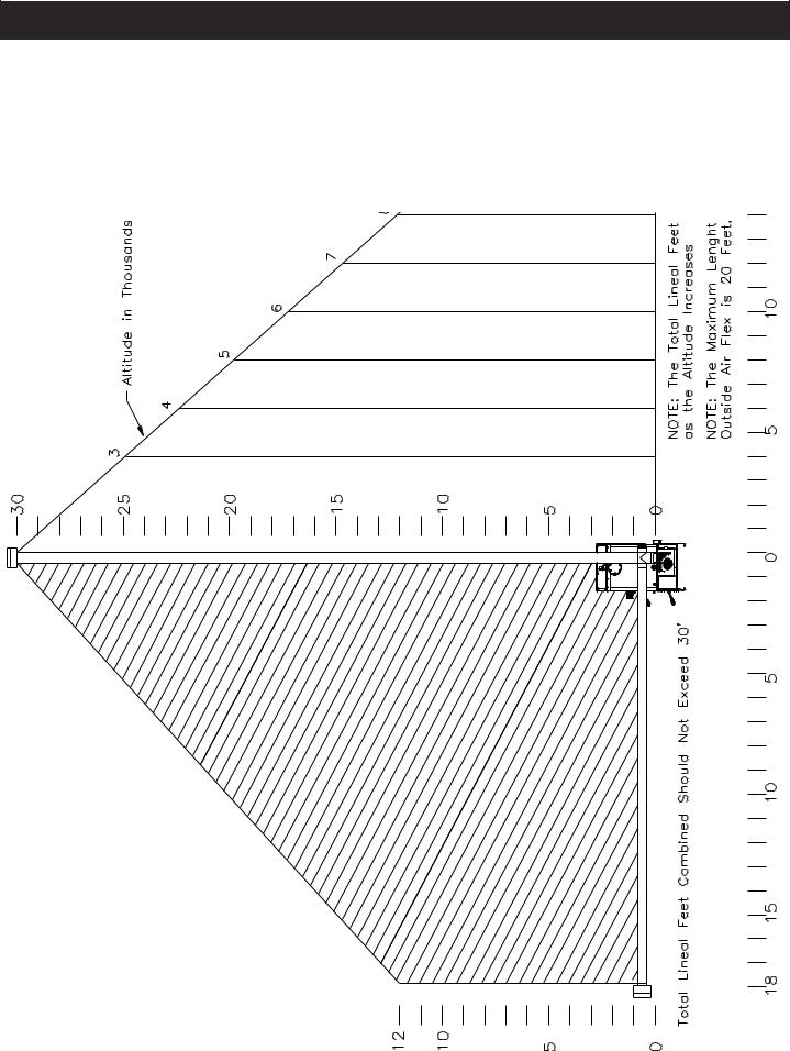
The maximum horizontal length is 18 feet. The minimum termination height above the exterior grade is 18”. The maximum total length of any configuration is 30 feet*.
* ( see venting graph on page 9 for exceptions )
NOTE: Cleanout Tee’s should always be used on the transitions to horizontal pipe to allow easy access for cleaning.
The venting graph allows for (one) 90 deg. or Tee fitting in any configuration.
If more 90’s, T’s, or 45’s are needed the total length must be adjusted to allow for the added restriction.
Up to four (4) additional 90’s, Tee’s, or equivalent 45’s can be added as long as the overall length is adjusted in accordance with the values listed below.
( See the venting graph on page 9.)
Each Vertical ---- 90 deg. or T subtract 2.5 feet Each Vertical ---- 45 deg. subtract 1.5 feet Each Horizontal - 90 deg. or T subtract 5.0 feet Each Horizontal - 45 deg. subtract 2.5 feet
Any exterior venting (vent pipe exposed to outside ambiant temperatures) should be kept to a minimum, due to potential condensation problems.
This is especially important in high humidity cold weather climates, such as maritime areas, lake shores, and low river valleys.
11

Venting Installation
Chimneys taller than 20’ above the connection will require a draft test to determine if the draft is too high.
Note: The High Burn Draft should not exceed .85 IWC. Some form of a restrictor plate may be required at the top of high chimneys to reduce the draft. See page 19 for the Draft Test procedure.
The PB105 Boiler may be used and installed into an existing masonary or ClassA metal chimney.
Certain Canadian and Local Codes may require that the chimney be fully relined.
It Can Not be installed in a chimney serving another appliance.
The chimney should be cleaned and or inspected before installation.
Creosote - Formation and Need for Removal - When wood is burned slowly, it produces tar and other organic vapors, which combine with expelled moisture to form creosote. The creosote vapors condense in the relatively cool chimney flue of a slow-burning fire. As a result, creosote residue accumulates on the flue lining. When ignited, this creosote makes an extremely hot fire. The pellet vent pipe should be inspected at least twice monthly during the heating season to determine if a creosote buildup has occurred. If creosote has accumulated it should be removed to reduce the risk of a chimney fire.
Guidance on minimizing creosote formation and the need for periodic creosote removal: The chimney should be inspected during the heating season to determine if a creosote build-up has occurred. If a significant layer of creosote has
accumulated (3mm or more) it should be removed to reduce the risk of a chimney fire.
12
INSTALLATION IS TO BE PERFORMED BY A
DO NOT INSTALL A FLUE DAMPER IN THE
EXHAUST VENTING SYSTEM OF THIS UNIT.
DO NOT CONNECT THIS UNIT TO A
APPLIANCE.
INSTALL VENT WALL PASS-THROUGHS AT
CLEARANCES SPECIFIED BY THE VENT
WARNINGOtherDKeepN TE:NOTcombustibleexampleAllINSTALLinKEEPtallationofmaterials1suchpossibleCOMBUSTINclearSLEEPINGinst llncesationsBLESgrand1rss,ofROOMleaves,thAWAYstrictionsventingetc. . |
O |
T |
E |
: |
U |
s |
 Loading...