


HS 500
INTEGRATED HOME THEATER SYSTEM
OWNER’S MANUAL

SAFETY INFORMATION
1.Read these instructions.
2.Keep these instructions.
3.Heed all warnings.
4.Follow all instructions.
5.Do not use this apparatus near water.
6.Clean only with a dry cloth.
7.Do not block any ventilation openings. Install in accordance with the manufacturer’s instructions.
8.Do not install near any heat sources such as radiators, heat registers, stoves or other apparatus (including amplifiers) that produce heat.
9.Do not defeat the safety purpose of the polarized or groundingtype plug. A polarized plug has two blades with one wider than the other. A grounding-type plug has two blades and a third grounding prong. The wide blade or the third prong is provided for your safety. If the provided plug does not fit into your outlet, consult an electrician for replacement of the obsolete outlet.
10.Protect the power cord from being walked on or pinched, particularly at plugs, convenience receptacles and the point where they exit from the apparatus.
11.Only use attachments/accessories specified by the manufacturer.
12.Use only with the cart, stand, tripod, bracket or
table specified by the manufacturer or sold with the apparatus. When a cart is used, use caution when moving the cart/apparatus combination to avoid injury from tip-over.
13. Unplug this apparatus during lightning storms or when unused for long periods of time.
14.Refer all servicing to qualified service personnel. Servicing is required when the apparatus has been damaged in any way, such as power supply cord or plug is damaged, liquid has been spilled or objects have fallen into the apparatus, the apparatus has been exposed to rain or moisture, does not operate normally, or has been dropped.
15.Do not expose this apparatus to dripping or splashing and ensure that no objects filled with liquids, such as vases, are placed on the apparatus.
16.To completely disconnect this apparatus from the AC Mains, disconnect the power supply cord plug from the AC receptacle.
17.The mains plug of the power supply cord shall remain readily operable.
18.Do not expose batteries to excessive heat such as sunshine, fire or the like.
The lightning flash with arrowhead symbol, within an equilateral triangle, is intended to alert the user to the presence of uninsulated “dangerous voltage” within the product’s enclosure that may
be of sufficient magnitude to constitute a risk of electric shock to persons.
The exclamation point within an equilateral triangle is intended to alert the user to the presence of important operating and mainte-
 nance (servicing) instructions in the literature accompanying the product.
WARNING: To reduce the risk of fire or electric shock, do not expose this apparatus to rain or moisture.
2

SAFETY INFORMATION
Important Safety Information
Verify Line Voltage Before Use
Your HS 500 has been designed for use with 120-volt AC current. Connection to a line voltage other than that for which it is intended can create a safety and fire hazard and may damage the unit.
If you have any questions about the voltage requirements for your specific model, or about the line voltage in your area, contact your selling dealer before plugging the unit into a wall outlet.
Do Not Use Extension Cords
To avoid safety hazards, use only the power cord attached to your unit. We do not recommend that extension cords be used with this product. As with all electrical devices, do not run power cords under rugs or carpets or place heavy objects on them. Damaged power cords should be replaced immediately by an authorized service center with a cord meeting factory specifications.
when placing the unit on soft woods or other materials that may be damaged by heat or heavy objects. Some surface finishes may be particularly sensitive to absorbing such marks, due to a variety of factors beyond Harman Kardon's control, including the nature of the finish, cleaning materials used, and normal heat and vibration caused by the use of the product, or other factors. We recommend that caution be exercised in choosing an installation location for the component and in normal maintenance practices, as your warranty will not cover this type of damage to furniture.
Cleaning
When the unit gets dirty, wipe it with a clean, soft, dry cloth. If necessary, and only after unplugging the AC power cord, wipe it with a soft cloth dampened with mild soapy water, then a fresh cloth with clean water. Wipe it dry immediately with a dry cloth. NEVER use benzene, aerosol cleaners, thinner, alcohol or any other volatile cleaning agent. Do not use abrasive cleaners, as they may damage the finish of metal parts. Avoid spraying insecticide near the unit.
Handle the AC Power Cord Gently
When disconnecting the power cord from an AC outlet, always pull the plug; never pull the cord. If you do not intend to use the unit for any considerable length of time, disconnect the plug from the AC outlet.
Do Not Open the Cabinet
There are no user-serviceable components inside this product. Opening the cabinet may present a shock hazard, and any modification to the product will void your guarantee. If water or any metal object such as a paper clip, wire or staple accidentally falls inside the unit, disconnect it from the AC power source immediately, and consult an authorized service center.
CATV or Antenna Grounding
If an outside antenna or cable system is connected to this product, be certain that it is grounded so as to provide some protection against voltage surges and static charges. Section 810 of the National Electrical Code, ANSI/NFPA No. 70-1984, provides information with respect to proper grounding of the mast and supporting structure, grounding of the lead-in wire to an antenna discharge unit, size of grounding conductors, location of antenna discharge unit, connection to grounding electrodes and requirements of the grounding electrode.
NOTE TO CATV SYSTEM INSTALLER: This reminder is provided to call the CATV (cable TV) system installer’s attention to article 820-40 of the NEC, which provides guidelines for proper grounding and, in particular, specifies that the cable ground shall be connected to the grounding system of the building, as close to the point of cable entry as possible.
Installation Location
•To ensure proper operation and to avoid the potential for safety hazards, place the unit on a firm and level surface. When placing the unit on a shelf, be certain that the shelf and any mounting hardware can support the weight of the product.
•Make certain that proper space is provided both above and below the unit for ventilation. If this product will be installed in a cabinet or other enclosed area, make certain that there is sufficient air movement within the cabinet. Under some circumstances, a fan may be required.
•Do not place the unit directly on a carpeted surface.
•Avoid installation in extremely hot or cold locations, or in an area that is exposed to direct sunlight or heating equipment.
•Avoid moist or humid locations.
•Do not obstruct the ventilation slots on the top of the unit, or place objects directly over them.
•Due to the weight of the HS 500 and the heat generated by the amplifiers, there is the remote possibility that the rubber padding on the bottom of the unit’s feet may leave marks on certain wood or veneer materials. Use caution
Moving the Unit
Before moving the unit, be certain to disconnect any interconnection cords with other components, and make certain that you disconnect the unit from the AC outlet.
Important Information for the User
This equipment has been tested and found to comply with the limits for a Class B digital device, pursuant to Part 15 of the FCC Rules. The limits are designed to provide reasonable protection against harmful interference in a residential installation. This equipment generates, uses and can radiate radio-frequency energy and, if not installed and used in accordance with the instructions, may cause harmful interference to radio communication. However, there is no guarantee that harmful interference will not occur in a particular installation. If this equipment does cause harmful interference to radio or television reception, which can be determined by turning the equipment off and on, the user is encouraged to try to correct the interference by one or more of the following measures:
•Reorient or relocate the receiving antenna.
•Increase the separation between the equipment and receiver.
•Connect the equipment into an outlet on a circuit different from that to which the receiver is connected.
•Consult the dealer or an experienced radio/TV technician for help.
This device complies with Part 15 of the FCC Rules. Operation is subject to the following two conditions: (1) this device may not cause harmful interference, and (2) this device must accept interference received, including interference that may cause undesired operation.
NOTE: Changes or modifications may cause this unit to fail to comply with Part 15 of the FCC Rules and may void the user’s authority to operate the equipment.
Unpacking
The carton and shipping materials used to protect your new receiver during shipment were specially designed to cushion it from shock and vibration. We suggest that you save the carton and packing materials for use in shipping if you move, or should the unit ever need repair.
To minimize the size of the carton in storage, you may wish to flatten it. This is done by carefully slitting the tape seams on the bottom and collapsing the carton. Other cardboard inserts may be stored in the same manner. Packing materials that cannot be collapsed should be saved along with the carton in a plastic bag.
If you do not wish to save the packaging materials, please note that the carton and other sections of the shipping protection are recyclable. Please respect the environment and discard those materials at a local recycling center.
It is important that you remove the protective plastic film from the front-panel lens. Leaving the film in place will affect the performance of your remote control.
3

STAPLE INVOICE HERE
4

TABLE OF CONTENTS
2 SAFETY INFORMATION
6 INTRODUCTION
8 FRONT-PANEL CONTROLS
10 REAR-PANEL CONNECTIONS
12 REMOTE CONTROL FUNCTIONS
15INTRODUCTION TO HOME THEATER
16CONNECTIONS
16 Speaker Connections
16 Subwoofer
16Connecting External Source Devices to the HS 500
17Audio Connections
17 |
Digital Audio |
17 |
Analog Audio |
17 |
Video Connections |
17 |
Digital Video Connections |
17 |
Analog Video Connections |
18 |
Antennas |
18Remote IR Input and Output
19SPEAKER PLACEMENT
20INSTALLATION
20 Step One – Connect the Speakers
20 Step Two – Connect the Subwoofer
20 Step Three – Connect the Antennas
20 Step Four – Connect Any External Source Components
22 Step Five – Connect Video Display
22 Step Six – Plug In AC Power
22 Step Seven – Insert Batteries in Remote
22 Step Eight – Program Sources Into the Remote
24 Step Nine – Turn On the HS 500
26 INITIAL SETUP
26 Using the On-Screen Menu System
26 Step One – System Setup
29 Step Two – Audio Setup
29Step Three – Configure Speakers
30Step Four – Video Setup
31Step Five – Video Adjustments
33Step Six – Configure Sources
34OPERATION
34Turning On the HS 500
34Volume Control
34Mute Function
34Tone Controls
35 Headphones
35Source Selection
36Using the HS 500 Disc Player
36Playback Basics
37Playback Features for DVD and CD Discs
39 |
DVD Playback |
44 |
CD Playback |
46 |
MP3, Windows Media and JPEG Playback |
48VCD Playback
49Programming a Playlist
50Using the HS 500 Tuner
52Selecting an External Source
52 |
TV Source |
52 |
Auxiliary Source |
52 |
Digital Input Source |
52Recording
53USB Source
54 |
ADVANCED FUNCTIONS |
54 |
Advanced Remote Control Functions |
54 |
Punch-Through Programming |
54 |
Macros |
54Resetting the Remote
55Processor Reset
55Memory
56TROUBLESHOOTING GUIDE
58TECHNICAL SPECIFICATIONS
58Trademark Acknowledgements
59GLOSSARY
61APPENDIX
WARNING
To prevent fire or shock hazard, do not expose this appliance to rain or moisture.
For Canadian model
This Class B digital apparatus complies with Canadian ICES-003.
For models having a power cord with a polarized plug: CAUTION: To prevent electric shock, match wide blade of plug to wide slot, fully insert.
Modèle pour les Canadien
Cet appareil numérique de la Classe B est conforme à la norme NMB-003 du Canada.
Sur les modèles dont la fiche est polarisee: ATTENTION: Pour éviter les chocs électriques, introduire la lame la plus large de la fiche dans la borne correspondante de la prise et pousser jusqu’au fond.
5

INTRODUCTION
Please register your product on our Web site at www.harmankardon.com.
Note: You’ll need the product’s serial number. At the same time, you can choose to be notified about our new products and/or special promotions.
WWW.HARMANKARDON.COM
Thank you for choosing Harman Kardon®!
In the years since Harman Kardon invented the high-fidelity receiver, we have taken to heart the philosophy of bringing the joy of home entertainment to as many people as possible, adding performance
and ease-of-use features that enhance the home entertainment experience. With the introduction of the HS series of home theater systems, Harman Kardon offers a complete home theater solution with a wealth of listening and viewing options in one sleek component. Each HS series system also includes a 5.1-channel loudspeaker system, a system remote control and all the cables and accessories you need to enjoy movies and music entertainment in your own home, when used with your television or video display.
To obtain the maximum enjoyment from your new HS system, we urge you to read this manual and refer back to it as you become more familiar with its features and their operation.
If you have any questions about this product, its installation or its operation, please contact your retailer or customer installer, or visit our Web site at www.harmankardon.com.
HS 500 5.1-Channel DVD Receiver |
Audio Inputs |
||
Audio Section |
• AM/FM tuner (internal) |
||
• 65 Watts x 5, five channels driven at full power at 6 ohms, |
• DVD-Audio/Video/CD player (internal) |
||
20Hz – 20kHz, <0.5% THD (surround modes); 325 watts total |
• TV |
||
|
|||
• Digital Path amplifier design |
• Auxiliary |
||
|
|||
• 192kHz/24-bit D/A conversion |
Digital Audio Inputs |
||
• Sampling upconversion to 96kHz |
|||
• Coaxial |
|||
Surround Modes |
|||
• Optical |
|||
• Dolby® Digital |
|||
• USB (front-side and rear panels) |
|||
• Dolby Pro Logic® II (Movie and Music) |
|||
|
|
||
• Dolby Pro Logic |
|
|
|
|
1 |
||
• DTS® (5.1) |
|
||
• Stereo (Surround Off) |
|
||
|
|
|
|
|
NOTE: This player is designed and manufactured for compatibility with |
||
|
Region Management Information that is encoded on most DVD discs. |
||
|
This player is designed only for playback of discs with Region Code 1, |
||
|
or for discs that do not contain Region Code information. If there is any |
||
|
other Region Code on a disc, that disc will not play on the DVD. |
||
6

Outputs
•Subwoofer output
•Analog audio
•Video monitor (composite, S-video, component and HDMI)
•One coaxial digital audio
•Headphone
•Subwoofer trigger
Ease of Use
•Graphic user interface with composite, S-video, component video and HDMI
•Dot-matrix front-panel display
•Color-coded connections
•Programmable, learning six-device main remote control
DVD Player
•Plays 5-inch (12cm) and 3-inch (8cm) discs
•Video formats supported: DVD, DVD-R/RW, DVD+R/RW, VCD, SVCD
•Audio formats supported: DVD-Audio, CD, CD-R/RW, MP3, Windows® Media WMA
•Still-image formats supported: JPEG, Kodak® Picture Disc
•Video upscaling to 720p and 1080i
•Progressive-scan video outputs
•MP3 bit rates: 32kbps – 320kbps
•WMA bit rates: 16kbps – 192kbps
•JPEG resolution supported: 5 megapixels, 5MB file size
•Still-image rotation in 90-degree increments
•Thumbnail still-image menu
•Internal video test signal
•Fast Play: 2x, 4x, 16x, 100x
•Slow Play: 1/2x, 1/4x, 1/8x, 1/16x
•Zoom (DVDs, VCDs and JPEGs): 1x, 2x, 3x, 4x, 5x (two steps only for VCDs)
•Random Play (CDs only)
•Repeat Play: 1 group/title, 1 track/chapter, 1 folder, 1 disc
•A-B Repeat Play (DVDs, CDs and VCDs only)
•Parental control system with user-programmable password
INTRODUCTION
•Disc recognition for up to 100 discs
•Playback control for VCDs
•Aspect-ratio adjustment
Supplied Accessories
The following accessory items are supplied with the HS 500. If any of these items is missing, please contact Harman Kardon customer service at www.harmankardon.com.
•System remote control
•AM loop antenna
•FM wire antenna
•Three AAA batteries
•AC power cord
•HDMI cable
7

FRONT-PANEL CONTROLS
Standby/On Switch: This is an electrical switch that turns the
HS 500 on for playback, or leaves it in standby mode for quick turn-on using this switch or the remote control.
Power Indicator: This LED surrounds the Standby/On Switch. When the HS 500 is plugged into AC power, the LED turns amber to indicate that the HS 500 is in Standby mode (ready to be turned on). When the HS 500 is turned on (by pressing the Standby/On Switch or one of the Source Selectors on the remote), the LED turns blue. If this LED ever turns red, immediately unplug the HS 500. Check the speaker-wire connections to make sure no wires are shorting out by touching each other. If the LED remains red, bring the HS 500 to an authorized Harman Kardon service provider.
Open/Close: Press this button to open or close the disc drawer. When the HS 500 is in standby mode, press this button to turn on the HS 500 and open the drawer. Before pressing this button, always make sure no objects are blocking the drawer. Remember to close the door or turn off the HS 500 when you have finished. The door will only close automatically when the unit is turned off.
Volume Control: Turn this knob to raise or lower the volume, which will be shown on screen as an increasing or decreasing row of bars in the Message Display.
Message Display: Various messages appear in this display in response to commands. In addition, a variety of indicators will
light at various times to display the current source, playback mode (if appropriate), video settings or other aspects of the HS 500’s status as described throughout this manual.
Disc Drawer: This drawer holds a disc that is played in the HS 500. Press the Open/Close button on top of the HS 500 to access it. Be sure to carefully seat all discs in the recess in the drawer tray. Remember to close the drawer when you are finished, as it will not close automatically without turning off the unit.
Headphone Jack: Insert a 1/8" headphone plug into this jack for private listening. An optional adapter is necessary to use 1/4" or other size headphone plugs.
USB 1 Port: Gently insert a flash drive, card reader, digital camera or other USB device, or a USB standard-A cable connected to a USB device, in this port. Be certain to orient the plug’s plastic tongue so that it will insert adjacent to the receptacle’s tongue, and seat the plug fully.
You may insert or remove the device at any time; there is no installation or ejection procedure. The HS 500 is capable of playing MP3 and Windows Media® WMA audio files, and MPEG 2 and uncompressed AVI files that are stored on the device. The HS 500 can also display still-image files, but only in the JPEG format. Do not connect a PC or other USB host/controller to this port, or you may damage both the HS 500 and your device.
8

Standby/On
Power Open/Close
Indicator
Disc Drawer |
Volume Control |
Message Display |
|
|
|
and Indicators |
|
|
|
Headphone Jack |
|
|
|
|
|
|
|
USB 1 Port |
|
|
|
|
|
NOTE: To make it easier to follow the instructions throughout the manual that refer to this illustration, a copy of this page may be downloaded from the Product Support section at www.harmankardon.com.
9
CONTROLS PANEL-FRONT

REAR-PANEL CONNECTIONS
AM Antenna Terminals: Assemble the AM loop antenna supplied and make sure to connect the white wire to the “AM” terminal and the black wire to the “GND” terminal.
FM Antenna Terminal: Connect the included FM antenna to its terminal.
Front, Center and Surround Speaker Outputs: Use twoconductor speaker wire to connect each set of terminals to the correct speaker. Remember to observe the correct polarity (positive and negative connections). Always connect the positive lead to the colored terminal on the HS 500 and the red terminal on the speaker. Connect the negative lead to the black terminal on both the HS 500 and the speaker. See the Connections section for more information on connecting your speakers.
Subwoofer Output: Connect a powered subwoofer to this jack.
Subwoofer Trigger Output: A 1/8" mini-plug cable is supplied with the speakers included in the HS 500 system. Connect one end of the cable to this jack, and the other end to the trigger input on the subwoofer to automatically turn on the subwoofer whenever the HS 500 system is turned on. The subwoofer’s master power switch must be turned on for the trigger turn-on to operate.
USB 2 Port: Gently insert a flash drive, card reader, digital camera or other USB device, or a USB Standard-A cable connected to a USB device, in this port. Be certain to orient the plug’s plastic tongue so that it will insert adjacent to the receptacle’s tongue, and seat the plug fully.
You may insert or remove the device at any time; there is no installation or ejection procedure. The HS 500 is capable of playing MP3 and Windows Media® WMA audio files, and MPEG 2 and uncompressed AVI video files that are stored on the device. The HS 500 can also display still-image files, but only in the JPEG format. Do not connect
a PC or other USB host/controller to this port, or you may damage both the HS 500 and your device.
HDMI™ Output: HDMI (High-Definition Multimedia Interface™) is a newer type of connection for transmitting digital audio and video signals between devices. If your video display is HDMI-capable, you may connect the HDMI output to your video display for improved
video performance. It is recommended that you disable the HDMI audio function of your video display to benefit from the HS 500’s multichannel audio processing.
Remote Infrared (IR) Input and Output: When the remote IR sensor on the front panel is blocked, such as when the HS 500 is
placed inside a cabinet, connect an optional IR receiver to the Remote IR Input jack for use with the remote control. The Remote IR Output may be connected to the Remote IR Input of a compatible source device (or other product) to enable remote control through the HS 500. When several source devices are used, connect them in “daisy chain” fashion.
Composite and S-Video Monitor Outputs: If your video display is not equipped with component video inputs, connect one of these monitor outputs to the corresponding inputs on your television or video display in order to view the sources. S-video is preferred when available.
Auxiliary Analog Audio Inputs: These jacks may be used to connect an audio-only source component (e.g., tape deck). Do not connect a turntable to these jacks without a phono preamp.
Analog Audio Outputs: These jacks may be used to connect a CDR or another audio-only recorder.
TV Analog Audio Inputs: Depending on how you receive broadcast television, connect the analog audio outputs of your cable television, satellite or HDTV set-top box to these inputs. Connect the video output of any of these devices directly to your video display or television. If you receive television programming using an antenna and tuner built into the television set, connect the TV’s analog audio outputs to these jacks to take advantage of the HS 500’s high-quality audio performance.
Coaxial and Optical Digital Audio Inputs: If your source has a compatible digital audio output, connect it to one of these jacks. Remember to use only one type of digital audio connection for each source.
Coaxial Digital Audio Output: If you have connected an audio recorder to one of the digital audio inputs, you may connect the coaxial digital audio output to the recorder’s input.
Component Video Monitor Outputs: If your television or video display is component-video-capable, you may connect these jacks to the corresponding inputs on your video display.
AC Power Input: After you have made all other connections, plug the AC power cord into this input and into an unswitched outlet.
10
Optical Digital |
|
|
Coaxial Digital |
Auxiliary Analog |
|
|
|||||||
Audio Input |
|
|
Audio Output |
Audio Inputs |
AM Antenna |
||||||||
|
Coaxial Digital |
Analog |
|
TV Analog |
|
|
|||||||
|
Audio Input |
Audio Outputs |
Audio Inputs |
|
|
||||||||
|
|
|
|
|
|
|
|
|
|
|
|
|
|
|
|
|
|
|
|
|
|
|
|
|
|
|
|
|
|
|
|
|
|
|
|
|
|
|
|
|
|
|
|
|
|
|
|
|
|
|
|
|
|
|
|
|
|
|
|
|
|
|
|
|
|
|
|
|
|
|
|
|
|
|
|
|
|
|
|
|
|
|
|
AC Power Input |
Subwoofer |
USB 2 |
Remote |
|
Component Video |
S-Video Monitor |
|
Output |
Port |
IR Output |
|
Monitor Outputs |
Output |
|
|
|
|
|
|||||
Speaker Outputs |
Subwoofer |
Remote |
HDMI |
Composite Video |
FM Antenna |
||
|
Trigger Output |
IR Input |
Output |
Monitor Output |
|
||
NOTE: To make it easier to follow the instructions throughout the manual that refer to this illustration, a copy of this page may be downloaded from the Product Support section at www.harmankardon.com.
11
CONNECTIONS PANEL-REAR

REMOTE CONTROL FUNCTIONS
The HS 500 remote is capable of controlling four devices, including the HS 500 with its internal disc player and tuner, as well as a TV and devices connected to the Auxiliary and Digital Audio Inputs. Each time you wish to use the codes for any component, press the Selector button for that component to change the button functions to the correct codes.
Each Source Selector is used to power on the HS 500, select the source indicated, and switch the remote’s mode to operate the source and the HS 500 system, i.e., volume, mute, source selection and on-screen displays. The Source Selectors that operate the HS 500’s internal sources, including the DVD player, the tuner and the USB ports, are not programmable. As explained in the Initial Setup section, you may program the TV, Auxiliary and Digital Input Source Selectors to operate any external components you connect to the HS 500.
TV: Selects the source connected to the analog or digital audio input assigned to the TV and switches the remote to operate a television set.
Disc: Selects the HS 500’s internal disc player as the source and switches the remote to Disc mode.
Radio: Selects the HS 500’s internal tuner as the source and switches the remote to Tuner mode. Additional presses toggle the tuner band between AM and FM.
AUX: Selects the source connected to the Auxiliary analog audio inputs and switches the remote to operate the device.
D-IN: Selects the source connected to the digital audio input assigned to the D-IN source and switches the remote to operate the device.
USB 1: Selects the device connected to the front-panel USB port
(on right side of unit) as the source and switches the remote to operate the device using the HS 500’s on-screen menu system.
USB 2: Selects the device connected to the rear-panel USB port as the source and switches the remote to operate the device using the HS 500’s on-screen menu system.
NOTE: When the remote is switched to USB mode, it does not directly operate the USB device. The device is navigated and controlled indirectly using the HS 500’s on-screen menu system.
The Mode button allows you to change the remote’s mode to control a different device without selecting that device as a source. This is useful if, for example, you wish to adjust your video display screen (TV mode) while watching a DVD (Disc Mode).
Any given button may have different functions, depending on the remote’s mode. Some buttons are labeled with these functions. For example, the Preset Buttons are labeled for use as Picture Up/Down Buttons when viewing JPEGs on a CD or USB device. See Table A8 in the appendix for listings of the different functions for each type of component.
IR Transmitter Lens: As buttons are pressed on the remote, infrared codes are emitted through this lens. Make sure it is pointing toward the component being operated. In Learning mode, the remote
receives codes transmitted by your source component’s original remote through this lens. The remote is then capable of storing the new code in the memory for a button you select. See the Installation section for more information.
Program Indicator: This LED lights up or flashes in one of three colors as the remote is programmed or operated.
System Power Off Button: Press this button to turn off the HS 500 or another device.
Screen Power On and Off: Press these buttons to turn your video display on or off.
Source Selectors: Press one of these buttons to select a source device, which is a section of the HS 500 (DVD player or tuner) or an external component where a playback signal originates, e.g., cable TV, satellite or HDTV tuner. This will also turn on the HS 500 and switch the remote to the codes that operate the source device.
TV/Video: This button has no effect on the receiver, but is used to switch video inputs on the TV.
SAP: This button toggles the SAP (Secondary Audio Program) feature on and off. Some television programs are broadcast with a second audio track, such as a translation into another language, and this button allows you to access that audio.
Mode: This button has no effect on the HS 500, but enables you to switch the remote to another mode so that it operates another device without selecting it as the source. Each press of the Mode button changes the remote’s mode in this order: TV, DISC, RADIO, AUX, D-IN, USB 1 and USB 2, and then back to TV again. The corresponding Source Selector will light to indicate the mode.
Presets/Picture Up/Down: When the tuner is the source, these buttons scroll through the preset stations. When the DVD player or USB is the source these buttons scroll through still images stored on a disc or USB device.
Disc Info: Press this button to display the Disc Information screen, which contains detailed information about the current disc.
Mute Button: Press this button to mute the HS 500’s speaker and headphones outputs temporarily. To end muting, press this button
or adjust the volume. Muting also ends when the system is turned off.
Volume Controls: Press these buttons to raise or lower the volume, which will be shown in decibels (dB) in the Message Display.
Subtitle: Press this button while a DVD containing subtitle information is playing to turn subtitles off or select a subtitle language. This setting will only be in effect for the current disc.
NOTE: When you wish to make a recording, if you have programmed the recorder’s control codes into the remote, you will need to simultaneously press both the Subtitle button and the Record button to transmit the Record control code.
12

REMOTE CONTROL FUNCTIONS
NOTE: To make it easier to follow the instructions throughout the manual that refer to this illustration, a copy of this page may be downloaded from the Product Support section at www.harmankardon.com.
13

REMOTE CONTROL FUNCTIONS
Audio: Press this button while a DVD is playing to display the current audio track information and to select another audio format.
Setup Menu: Press this button to access the System Setup menu. See the Initial Setup section for more information.
Disc Menu: Press this button while a DVD is playing to view the disc’s menu.
Navigation and Enter Buttons: These buttons are used together to make selections within the on-screen menu system.
Status: When a DVD or VCD is playing, press this button to view the Status Bar, which contains playback mode information.
On-Screen Display (OSD): Press this button to activate the on-screen menu system.
Playlist: Each press of this button toggles between playback in the disc’s original order and play of a previously programmed playlist. Press the Play Button to begin playback.
Random: This button turns on or off random play mode, which plays the tracks on a CD in random order.
Repeat: Press this button repeatedly to cycle through the repeat modes available with the current disc. Repeat may also be used with the tracks stored on a device connected to one of the USB ports. This button is not used to access A-B Repeat mode.
Angle: When a DVD encoded with multiple camera angles is playing and when the Angle Icon appears to indicate that the multiple-angle passage has been reached, press this button to cycle through the various available angles.
This button is also used to rotate still images. Each press rotates the image 90 degrees.
Macros: These buttons may be programmed to execute long command sequences with a single button press. They are useful for programming the command to turn on or off all of your components, or for accessing specialized functions for a different component than you are currently operating.
Numeric Keys: Use these buttons to enter radio station frequencies when using the tuner, or to select station presets. When a disc is playing, you may directly enter a track or chapter number to skip to that section of the disc.
Clear: Press this button to clear a radio station frequency or other number you have started to enter. This button may also be used to clear the on-screen displays. Press and hold this button for 5 seconds to reset the HS 500 to its factory-default settings.
Zoom: When viewing a DVD, VCD or JPEG still image, press this button repeatedly to enlarge the on-screen image by 2x, 3x, 4x or 5x (2x or 3x only for VCDs) before returning to the original size. While enlarged, use the Navigation buttons to explore the image.
A-B Repeat: While a disc is playing, the A-B Repeat function allows you to repeatedly play a passage, which may include several tracks or chapters. Press the button once to select the starting point (“A”), and a second time to select the end of the passage (“B”). Press the button again to end repeat play.
Pre. Ch: This button has no function with the HS 500. However, for many televisions pressing this button returns the TV to the previous channel.
Recall: This button has no function with the HS 500. However, for many televisions pressing this button displays the channel number, time or other information.
Picture-in-Picture: This button has no function with the HS 500. However, for many televisions pressing this button activates the picture- in-picture function for simultaneous viewing of two channels or inputs.
Source Video Output: This button selects the S-video, component video or HDMI output to be used when the internal disc player or a device connected to one of the USB ports is the source. Since the
HS 500 cannot output S-video and component video simultaneously, the S-video or YUV (for component video) indicator will light in the front-panel display when that video output has been selected.
Source Video Format: This button selects the upscaled video output resolution (480i, 720p, 1080i) when the internal disc player or a device connected to one of the USB ports is the source. The 720p or 1080i indicator will light in the front-panel display to indicate the upscaled resolution.
Aspect Ratio: This button has no effect on the HS 500, but pressing it adjusts the aspect ratio on some video displays.
Open/Close: Press this button to open or close the disc drawer. If the HS 500 is in standby mode, pressing this button will turn it on.
Learn: The HS 500 remote is capable of “learning” individual IR codes from the original remote that came with your TV or a device that is connected to the Auxiliary or Digital Audio Inputs. See the Installation section for instructions for learning remote codes. There is also a quick reference for learning remote codes on the back of the remote.
Transport Controls: These buttons are used to operate the HS 500’s internal disc player. Use the controls to skip forward or reverse by track or chapter; to fast-search forward or reverse; and to play, pause or stop the disc. After pressing the Pause button, the skip buttons may be used to step frame-by-frame through a video
presentation, and the fast-search buttons may be used for slow-play.
Title/Record: When used with the internal disc player, this button allows you to select from the titles stored on the disc, which may include “making of” or other featurettes. If you have connected a recorder to the HS 500, this button may be used to make recordings when it is pressed simultaneously with the Subtitle button.
Backlight: Press this button to turn on the backlight to make it easier to see the buttons in a darkened room. The backlight will remain on for a few seconds after your last button press before going out, or you may turn off the backlight by pressing this button again.
14

INTRODUCTION TO HOME THEATER
The HS 500 may be the first multichannel surround sound component you’ve owned. This introductory section will help you to familiarize yourself with the basic concepts, which make setup and operation smoother.
If you are already familiar with home theater, you may skip this section and proceed to the Connections section on page 16.
Typical Home Theater System
A home theater typically includes your audio/video receiver, which controls the system; a DVD player; a source component (e.g., a cable box, a satellite dish receiver, an HDTV tuner or simply an antenna connected to the TV) for television broadcasts; a video display (TV); and loudspeakers.
The HS 500 offers a simpler solution by integrating the DVD player with the receiver, resulting in a sleek, streamlined component with just a few connections needed to enjoy a complete home theater experience.
All of these components are connected by various types of cables for audio and video signals.
Multichannel Audio
The benefit of a home theater system is that several loudspeakers are used in various locations around the room to produce “surround sound,” immersing you in the musical or film presentation for increased realism.
The HS 500 may have up to five speakers connected to it (plus a subwoofer). Each speaker is powered by its own amplifier channel, and the subwoofer has its own amplifier on board.
•Front Left and Right – The main speakers are used the same way as in a two-channel system. However, you may notice that in many surround modes, these speakers are used more for ambient sound while the main action and dialogue are moved to the center speaker.
•Center – The center speaker is usually placed above or below the video screen, and is used mostly for dialogue in movies and television programs. This placement allows the dialogue to originate near the actors’ faces, for a more natural sound.
•Surround Left and Right – The surround speakers are used to improve directionality of ambient sounds. In addition, by using more loudspeakers in the system, more dynamic soundtracks may be played without risk of overloading any one speaker.
Many people expect the surround speakers to play as loudly as the front speakers. Although all of the speakers in the system will be calibrated to sound equally loud at the listening position, most sound tracks use the surround speaker for ambient effects only, and they program their materials to steer very little sound to these speakers.
•Subwoofer – A subwoofer is a special-purpose speaker designed to play only the lowest frequencies (bass). It is used to augment the smaller, limited-range satellite speakers used for the other channels. In addition, many digital-format programs, such as movies recorded in Dolby Digital, contain a special low-frequency effects (LFE) channel that is directed only to the subwoofer. The LFE channel packs the punch of a rumbling train or airplane, or the power of an explosion, adding realism and excitement to your home theater.
Surround Modes
There are different theories as to the best way to present surround sound and to distribute soundtrack information among the various speakers. A variety of algorithms have been developed in an effort to accurately reproduce the way we hear sounds in the real world. The result is a rich variety of surround mode options. Some modes are selected automatically, depending on the signal being received from the source. In many cases, you may select a surround mode manually.
Several companies have taken surround sound in slightly different directions. It is helpful to group the numerous surround modes either by their brand name, or by using a generic name:
•Dolby Laboratories, Inc., Modes:
ÍDolby Digital – This mode is encoded in the program material either on a disc or within a television broadcast. It provides up to five separate main audio channels and a dedicated low-frequency effects (LFE) channel.
ÍDolby Pro Logic II – This mode is derived by an analog decoder built into the HS 500 that derives five full-range, discrete main audio channels from matrix surround-encoded or 2-channel analog sources. Select from Dolby Pro Logic II Movie, which is optimized for movies and television programs; Dolby Pro Logic II Music, which is optimized for music selections; or Dolby Pro Logic, the original version that steered a mono signal containing information below 7kHz to the surround channels.
•DTS Mode – DTS is a digital surround format that is encoded in the program material. It uses a different encoding and decoding method than Dolby Digital to provide up to 5 discrete main channels, plus an LFE channel. The HS 500 is capable of playing DTS materials when the Original setting is selected for the audio mode.
•Stereo Mode – Two-channel mode with no surround sound.
These surround modes may be selected on the HS 500 using the DVD Sound Mode setting found in the Audio Setup submenu (for the Disc Player), or the Audio Mode Setting within the on-screen menu for each source. For digital audio sources, such as the internal disc player or any source using one of the digital audio inputs, select Original to benefit from any digital surround modes encoded in the source materials.
Digital modes, such as Dolby Digital and DTS, are only available with specially encoded programs, such as DVDs and digital cable or satellite television. Other modes may be used with various digital and analog signals to create a different surround presentation, or to use a different number of speakers. Surround mode selection depends upon the number of speakers in your system, the materials you are watching
or listening to, and your personal tastes. Feel free to experiment.
15

CONNECTIONS
There are different types of audio and video connections used to connect the HS 500 to the speakers and video display, and to connect any source devices to the HS 500. To make it easier to keep them all straight, the Consumer Electronics Association (CEA) has established
a color-coding standard. Table 1 may be helpful to you as a reference while you set up your system.
Table 1 – Connection Color Guide
Audio Connections
|
|
Left |
|
Right |
||||
Front (FL/FR) |
|
|
|
|
|
|
|
|
|
|
|
|
|
|
|
|
|
Center (C) |
|
|
|
|
|
|||
|
|
|
|
|
||||
|
|
|
|
|
||||
Surround (SL/SR) |
|
|
|
|
|
|||
|
|
|
|
|||||
|
|
|
|
|
|
|
|
|
Subwoofer (SUB) |
|
|
|
|
||||
|
|
|
|
|||||
Digital Audio Connections
Coaxial
Optical Input
Video Connections
Component |
Y |
Pb |
Pr |
Composite |
|
|
|
S-Video |
|
|
|
HDMI™ Connections
HDMI
Types of Connections
This section will briefly review different types of cables and connections that you may use to set up your system.
Speaker Connections
Speaker cables carry an amplified signal from the receiver’s speaker terminals to each loudspeaker. Speaker cables generally contain two wire conductors, or leads, inside plastic insulation. The two conductors are usually differentiated in some way, by using different colors, or stripes, or even by adding a ridge to the insulation.
The differentiation is important because each speaker must be connected to the HS 500’s speaker-output terminals using two wires, one positive (+) and one negative (–). This is called speaker polarity. It’s important to maintain the proper polarity for all speakers in the system. If some speakers have their negative terminals connected to the HS 500’s positive terminals, performance can suffer, especially for the low frequencies.
Always connect the positive terminal on the loudspeaker, which is colored red, to the positive terminal on the HS 500, which is colored as shown in the Connection Color Guide (Table 1). Similarly, always connect the black negative terminal on the speaker to the black negative terminal on the HS 500. The wires in the speaker system included with your HS 500 Home Theater System are color-coded with bands.
The HS 500 uses binding-post speaker terminals that can accept banana plugs or bare-wire cables, should you wish to upgrade your system in the future.
Banana plugs are simply plugged into the hole in the middle of the terminal cap. See Figure 1.
Figure 1 – Binding-Post Speaker Terminals With
Banana Plugs
 +
+
Bare wire cables are installed as follows (see Figure 2):
1.Unscrew the terminal cap until the pass-through hole in the collar is revealed.
2.Insert the bare end of the wire into the hole.
3.Screw the cap back into place until the wire is held snugly.
1 |
2 |
3 |
Figure 2 – Binding-Post Speaker Terminals With Bare Wires
Subwoofer
The subwoofer is a specialized type of loudspeaker that is usually connected in a different way. The subwoofer is used to play only the low frequencies (bass), which require much more power than the other speaker channels. In order to obtain the best results, the HS 500 includes a powered subwoofer that contains its own amplifier on board. A line-level (nonamplified) connection is made from the HS 500’s Subwoofer Output to a corresponding jack on the subwoofer.
See Figure 3.
Although the subwoofer output looks similar to the analog audio jacks used for the various components, it is filtered and only allows the low frequencies to pass. Don’t connect this output to your other devices.
Although doing so won’t cause any harm, performance will suffer.
Pre-out Subwoofer
Figure 3 – Subwoofer
Connecting External Source Devices to the HS 500
The HS 500 is designed to process audio input signals. These signals originate in what are known as “source devices,” including the internal DVD/CD player, a DVR (digital video recorder) or other recorder, a tape deck, a game console, a cable or satellite television box, a flash drive or an MP3 player. Although the tuner and disc player are built into the HS 500, they also count as sources, even though no external connections are needed, other than the FM and AM antennas.
In general, separate connections are required for the audio and video portions of the signal. The types of connections used depend upon what’s available on the source device, and for video signals, the capabilities of your video display.
16

CONNECTIONS
Audio Connections
There are two formats for audio connections: digital and analog. Digital audio signals are of higher quality, and are required for listening to sources encoded with digital surround modes, such as Dolby Digital and DTS. There are two types of digital audio connections commonly used: coaxial and optical. Either type of digital audio connection may be used for each source device, but never both simultaneously for the same source. However, it’s okay to make both analog and digital audio connections at the same time to the same source.
The HS 500 allows you to connect different devices to each of the TV and Auxiliary analog audio inputs, and the coaxial or optical digital audio inputs.
Digital Audio
Coaxial digital audio jacks are usually color-coded in orange. Although they look similar to analog jacks, they should not be confused, and you should not connect coaxial digital audio outputs to analog inputs or vice versa. See Figure 4.
Coaxial digital Coaxial audio cable 


Figure 4 – Coaxial Digital Audio
Optical digital audio connectors are normally covered by a shutter to protect them from dust. The shutter opens as the cable is inserted. See Figure 5.
Optical
Optical digital
audio cable
Figure 5 – Optical Digital Audio
Due to the nature of digital signals as binary bits, they aren’t subject to signal degradation the way analog signals are. Therefore, the quality of coaxial and optical digital audio connections should be the same,
although it is important to limit the length of the cable. Whichever type of connection you choose, Harman Kardon recommends that you always select the highest quality cables available within your budget.
Analog Audio
Analog connections require two cables, one for the left channel (white) and one for the right channel (red). See Figure 6. These two cables are often attached to each other for most of their length. Most sources that have digital audio jacks also have analog audio jacks, although some older types of sources, such as tape decks, have only analog jacks. For sources that are capable of both digital and analog audio, you may wish to make both connections. If you wish to record materials from DVDs or other copy-protected sources, you may only be able to do so using analog connections. Remember to comply with all laws regarding copyright if you choose to make a copy for your own personal use.
Analog audio |
L |
|
|
cable (RCA) |
R |
Figure 6 – Analog Audio
Video Connections
Although some sources produce an audio signal only (e.g., tape deck), many sources output both audio and video signals (e.g., cable television box, HDTV tuner, satellite box, VCR, DVR). You will need to connect one of the HS 500’s video outputs to your video display.
Digital Video Connections
The HS 500 is equipped with an HDMI (High-Definition Multimedia Interface) output. HDMI is capable of carrying digital audio and video information using a single cable, delivering high-quality picture and sound.
There are different versions of HDMI, depending on the capability of the source device and the type of signal it is capable of transmitting via the HDMI connection.
The physical HDMI connection is simple. The connector is shaped for easy plug-in (see Figure 7). If your video display has a DVI input, you may use an HDMI-to-DVI adapter (not included) to connect it to the HDMI Output.
Figure 7 – HDMI Connection
Analog Video Connections
There are three types of analog video connections: composite video, S-video and component video.
Composite video is the basic connection most commonly available. The jack is usually color-coded yellow, and looks like an analog audio jack, although it is important never to confuse the two. Do not plug a composite video cable into an analog or coaxial digital audio jack, or vice versa. Both the chrominance (color) and luminance (intensity) components of the video signal are transmitted using a single cable. See Figure 8.
Composite video cable
Figure 8 – Composite Video
S-video, or “separate” video, transmits the chrominance and luminance components using separate wires contained within a single cable. The plug on an S-video cable contains four metal pins, plus a plastic guide pin. Be careful to line up the plug correctly when you insert it into the jack on the receiver, source or video display. See Figure 9.
S-video cable
Figure 9 – S-Video
Component video separates the video signal into three components – one luminance (“Y”) and two sub-sampled color signals (“Pb” and “Pr”) – that are transmitted using three separate cables. The “Y” cable is color-coded green, the “Pb” cable is colored blue and the “Pr” cable
is colored red. See Figure 10.
17 |
17 |

CONNECTIONS
Do not confuse component video connections with composite video (described above). Although the plugs and jacks may look similar, they are not compatible and cross-connecting them will result in no picture or a very distorted picture. Remember that component video uses three connections, colored green, blue and red, while composite video uses a single connection, which is often color-coded yellow.
Component video cable
Figure 10 – Component Video
If it’s available on your video display, HDMI is recommended as the best-quality connection, followed in preference by component video, S-video and then composite video.
Antennas
The HS 500 uses separate terminals for the included FM and AM antennas that provide proper reception for the tuner.
The FM antenna uses a 75-ohm F-connector. See Figure 11.
Figure 11 – FM Antenna
The AM loop antenna needs to be assembled. Then connect the two leads to the spring terminals on the receiver, being certain to connect the white wire to the terminal marked “AM”, and the black wire to the terminal marked “GND.” See Figure 12.
Figure 12 – AM Antenna
Remote IR Input and Output
The HS 500 is equipped with an infrared input and output to facilitate use of your system with a remote control in a variety of situations.
When the HS 500 is placed in such a way that aiming the remote at the front-panel IR sensor is difficult, such as inside a cabinet or facing away from the listener, you may connect an external IR receiver, such as the optional Harman Kardon HE 1000, to the Remote IR Input jack.
If any of your source devices are equipped with a compatible remote IR input, you may use a 1/8" mini-plug interconnect cable (not included) to connect the Remote IR Output to the source device’s remote IR input, which will pass any applicable remote signals transmitted through the HS 500 to the source device. This enables you to control your sources even when the HS 500 itself is controlled via an external IR receiver.
To control more than one source device using the Remote IR Output, connect all sources in “daisy chain” fashion, with the HS 500’s Remote IR Output connected to the first device’s remote IR input, that device’s remote IR output connected to the next device’s remote IR input, and so forth.
NOTE: Not all remote controllable devices are equipped with compatible IR inputs and outputs. Check with the manufacturer of the source device for more information on the type of IR signal expected. The HS 500 will output a “stripped carrier”
IR signal.
18 |
18 |
SPEAKER PLACEMENT
Before you begin to connect cables, it is important to set up your speakers in their correct locations in the room.
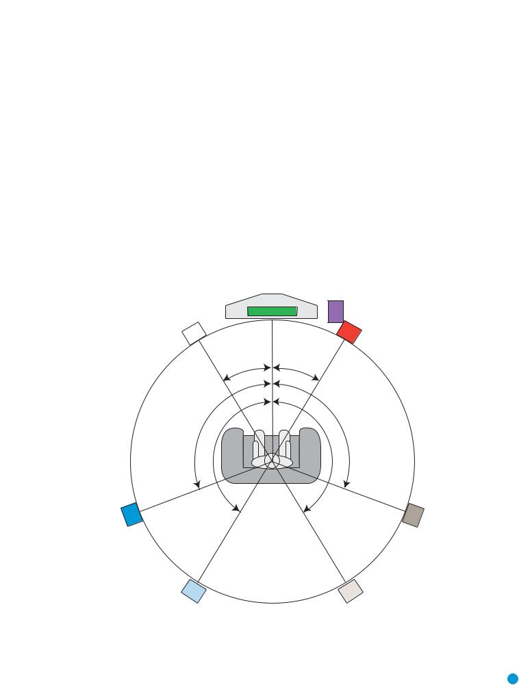
Optimally, the speakers should be placed in a circle with the listening position at its center. The distance from the listening position to the video display forms the radius of the circle. See Figure 13.
The speakers should be angled so that they directly face the listening position.
The center speaker is placed either on top of, below or on a shelf below the video display screen.
The front left and right speakers are placed along the circle, about 30 degrees from the center speaker and angled toward the listener.
It is best to place the front left/right and center speakers as close to the same height as possible, preferably at about the same height as the listener’s ears. In any event the center speaker should be no more than two feet above or below the left/right speakers.
The side surround speakers should be placed 110 degrees from the center speaker, that is, slightly behind and angled toward the listener. If this isn’t feasible, place the surround speakers behind the listener,
with each surround speaker facing the opposite-side front speaker. The surround speakers may be placed a little higher than the listener’s ears.
The subwoofer’s location is less critical, since low-frequency sounds are omnidirectional. Placing the subwoofer close to a wall or in a corner will reinforce the low frequencies, and may create a “boomy” sound. You may wish to experiment over time by placing the subwoofer where the listener normally sits and then walking around the room until the low frequencies sound best. Place the subwoofer in that spot.
Subwoofer
|
Video Screen |
|
Center Speaker |
Front Left |
Front Right |
Speaker |
Speaker |
30° |
30° |
110° |
110° |
150° |
150° |
Surround |
Surround |
Left Speaker |
Right Speaker |
Alternate placement |
Alternate placement |
for Surround |
for Surround |
Left Speaker |
Right Speaker |
Figure 13 – |
Speaker Placement |
19 |
19 |
INSTALLATION
You are now ready to connect the various components to the HS 500. Before beginning, make sure that all components, including the HS 500, are turned completely off and their power cords are unplugged. Don’t plug any of the power cords back in until you have finished making all of your connections.
The HS 500 generates heat while it is playing. Select a location that leaves several inches of space on all sides. It is preferable to avoid completely enclosing it inside a cabinet. It is also preferable to stack components on separate shelves rather than directly on top of the HS 500. Some surface finishes are delicate. Try to select a location with a sturdy surface finish.
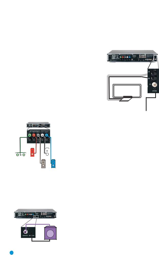
Step One – Connect the Speakers
If you have not yet done so, place your speakers in the listening room as described in the Speaker Placement section above.
Connect the center, front left, front right, surround left and surround right loudspeakers to the corresponding speaker terminals on the HS 500. Remember to maintain the proper polarity by always connecting the positive and negative terminals on each speaker to the positive and negative terminals on the receiver. Use the Connection Color Guide
on page 16 as a reference. See Figure 14.
|
|
|
|
|
|
|
|
|
|
C |
|
FR |
FL |
|
SR |
SL |
Figure 14 – Speaker Connections |
Step Two – Connect the Subwoofer
Connect the Subwoofer Output on the HS 500 to the line-level input on your subwoofer. Use the 1/8-inch mini-plug cable packed with the speaker system to connect the Subwoofer Trigger on the HS 500 to the External Trigger Input on the subwoofer. See Figure 16. The trigger will automatically turn on the subwoofer when the HS 500 is turned on.
Consult the owner’s guide for the subwoofer for additional information.
SUB
Figure 16 – Subwoofer Connection
Step Three – Connect the Antennas
Connect the FM and AM antennas to their terminals. Keep in mind that the AM terminals are polarized. Connect the white lead to the AM terminal and the black lead to the GND terminal.
AM
Figure 16 – Antenna
FM Connections
Step Four (Optional) – Connect Any External
Source Components
Although the HS 500 already contains an FM/AM tuner and DVDAudio/Video player on board, you may have other components you would like to use with your home theater system. The HS 500 can accommodate up to two analog audio, two digital audio and two USB devices. You may connect different devices to the digital and analog audio inputs; they are treated as separate sources. You will notice that the HS 500 has no video inputs. Connect each source’s video output directly to your television, but connect its audio output to the HS 500 to benefit from the multichannel surround sound. If you wish to make a recording from the disc player, you will only be able to make an analog recording of copy-protected materials, and you will need to connect the video inputs of your recorder to either the composite or S-video output of the HS 500.
When deciding which components to connect to each input, bear in mind that the remote may be programmed to control the device. By default, the Auxiliary input is preprogrammed to operate a VCR or DVR (TiVo), and the digital inputs (D-IN) are preprogrammed to operate a cable or satellite set-top box. Thus, you may want to connect your components accordingly. However, you may reassign the product types when you program the remote, and any compatible component with the correct audio outputs may be connected to any of the sources.
Use the worksheets in the Appendix to note which connections you will use for each of your source devices.
For each source, select a source input (TV, AUX, D-IN). In Table 2 we recommend connecting certain types of sources to certain source inputs to make it easier to program and use the remote control.
Decide which audio connections you will use. If your source has them, use either the coaxial digital or the optical digital audio connection.
20 |
20 |
|
|
|
|
INSTALLATION |
||
Table 2 – Recommended Source Component Connections |
|
|
|
|||
|
|
|
|
|
|
|
|
Device Type |
HS 500 Source Input |
Audio Connections |
|
Video Connections |
|
|
|
|
|
|
|
|
|
VCR, DVR, PVR, |
• AUX |
• Analog inputs and outputs |
|
• Connect recorder’s video output directly |
|
|
TiVo® or other |
|
|
|
to video display |
|
|
|
|
|
|||
|
audio/video recorder |
• D-IN |
• Coaxial input and output |
|
• For recording, use S-video or |
|
|
|
|
|
|
composite video output |
|
|
|
|
|
|
|
|
|
CDR, MiniDisc, |
• AUX |
• Analog inputs and outputs |
|
Not required |
|
|
cassette |
|
|
|
|
|
|
• D-IN |
• Coaxial input and output |
|
|
|
|
|
|
|
|
|
||
|
|
|
|
|
|
|
|
TV, cable TV, satellite, |
• TV |
• Analog inputs or |
|
Not required for television set; connect other |
|
|
HDTV or other device |
|
• Coaxial or Optical input |
|
device’s video output directly to video display |
|
|
that delivers television |
• D-IN |
• Coaxial or Optical input |
|
|
|
|
programs |
|
|
|
||
|
|
|
|
|
|
|
|
|
|
|
|
|
|
|
Digital camera*, flash |
• USB 1 |
• Side input at front of unit |
|
Included in single USB connection |
|
|
drive, hard disc drive or |
• USB 2 |
• Rear-panel input |
|
|
|
|
other USB device** |
|
|
|
|
|
|
|
|
|
|
|
|
|
|
|
|
|
|
|
*The HS 500 is only compatible with cameras that output files in the JPEG format.
**The HS 500 is only compatible with video files in the MPEG 2 and AVI formats. Do not connect a PC or other “host” USB device to the HS 500’s USB ports.
Audio/Video Recorder
Select either the analog or digital audio connections for your recorder. Each connection is treated as a separate source by the HS 500.
If you are using analog audio, connect the analog audio outputs on your recorder to the AUX analog audio inputs on the HS 500, and the AUX analog audio outputs to the analog audio inputs on your recorder.
See Figure 17.
Figure 17 – AUX Analog Audio Inputs and Outputs
If you are using the digital audio connections, you will need to use the D-IN coaxial input and output, as there is no optical audio output on the HS 500. See Figure 18.
Figure 18 – D-IN Coaxial Digital Audio Input and Output
When connecting a recorder, be careful to always connect one device’s input to the other device’s output.
If you would like to record video from the HS 500’s internal disc player or a USB device, connect the recorder’s S- or composite video input to either the S- or composite video output on the HS 500. When recording from the S-video output, select the S-video output in the Video Setup Menu, as component and S-video outputs are not available simultaneously. Connect one video output on the recorder directly to your video display or television.
TV, Cable, Satellite, HDTV
Select either the analog or coaxial or optical digital audio connection for your device. You may select either for the TV source.
If you are using analog audio, connect the analog audio outputs on your TV or set-top box to the TV analog audio inputs on the HS 500.
See Figure 19.
Figure 19 – TV Analog Audio Inputs
If you are using digital audio, your TV or set-top box must have a compatible digital audio output, which should be connected to either the Coaxial or Optical Input on the HS 500. See Figure 20. The set-top box should be selected as the D-IN source.
Figure 20 – Coaxial and Optical Digital Audio Inputs
When you select TV as your source input, you may select between the analog audio (line) or either digital audio input.
If you are using a cable or satellite set-top box to receive television broadcasts, connect one of its video outputs directly to your video display.
21

INSTALLATION
Digital Camera, Flash Drive, Hard Disc Drive
The HS 500 is equipped with two independent USB ports for use with USB devices, but not “host” devices, such as your PC. Do not connect your PC to either of the HS 500’s USB ports.
The USB 1 port is located on the right side of the HS 500, near the front panel. See Figure 21.
Figure 21 – USB 1 Port
The USB 2 port is located on the rear panel. See Figure 22.
Figure 22 – USB 2 Port
You may connect any USB device, such as a digital camera, flash drive or hard disc drive to either USB port. The HS 500 will automatically recognize any of the following types of files stored on the device: MP3 or WMA audio; MPEG 2 or uncompressed AVI video; JPEG still image. You may navigate the files using the HS 500’s on-screen menu system, as explained in the Operation section.
NOTES:
•The HS 500 is not compatible with digital cameras that do not produce images in the JPEG file format.
•There is no special procedure for installing or removing USB devices; simply plug in or remove the device at any time.
Step Five – Connect Video Display
Only video connections should be made between the receiver and your video display (TV), unless your TV is the source for your television programming (see above).
Determine what types of video your display is capable of handling. Remember that HDMI is preferred, followed by component video S-video and then composite video.
Select the best type of video your display is capable of handling, and connect only one of the HS 500’s video outputs to your display. See Figure 23.
Figure 23 – Video Outputs
Step Six – Plug In AC Power
Having made all of your wiring connections, it is now time to power up the HS 500. The HS 500 comes with a detachable power cord, which enables you to pre-install all wiring before final installation of the HS 500. Connect the female end of the power cord to the HS 500’s
AC Input, and plug the other end of the cord into a working, unswitched AC outlet. See Figure 24. If you are using any external components with the HS 500 system, you may plug those into AC power at this time.
Figure 24 – AC Input for Power Cord
Step Seven – Insert Batteries in Remote
The HS 500 remote control uses three AAA batteries (included).
To remove the battery cover located on the back of the remote, firmly press the ridged depression and slide the cover towards the top of the remote.
Insert the batteries as shown in Figure 25, making sure to observe the correct polarity.
Figure 25 – Remote Battery
Compartment
When using the remote, remember to point the lens toward the front panel of the HS 500. Make sure no objects, such as furniture, are blocking the remote’s path to the receiver. Bright lights, fluorescent lights and plasma video displays may interfere with the remote’s functioning. The remote has a range of about 20 feet, depending on the lighting conditions. It may be used at an angle of up to 30 degrees to either side of the HS 500.
If the remote seems to operate intermittently, or if pressing a button on the remote does not cause one of the source selectors to light up, then make sure the batteries have been inserted correctly, or replace all three batteries with fresh ones.
Step Eight – Program Sources Into the Remote
The HS 500 remote is capable of controlling not only the HS 500, but it may also be programmed to control many brands and models of VCRs, cable boxes, satellite receivers, cassette decks and TVs.
It may help to think of the remote as a book with pages. Each page represents the button functions for a different device. In order to access the functions for a particular device, you first need to turn to that page. This is done by pressing the Source Selector buttons to access the codes for the devices programmed into the remote. There is no “page” specifically set aside for the HS 500’s system functions. Instead, the volume and audio controls are always active, and the functions for the internal disc player and tuner are active when those sources are selected.
22
 Loading...