


HK 3490
STEREO RECEIVER OWNER’S MANUAL
SAFETY INFORMATION
Important Safety Instructions
1.Read these instructions.
2.Keep these instructions.
3.Heed all warnings.
4.Follow all instructions.
5.Do not use this apparatus near water.
6.The A/V receiver’s cabinet may be cleaned by gently wiping with a soft cotton or microfiber cloth. Do not use water or any liquid cleaners.
7.Do not block any of the ventilation openings. Install in accordance with the manufacturer’s instructions.
8.Do not install near any heat sources such as radiators, heat registers, stoves or other apparatus (including amplifiers) that produce heat.
9.Do not defeat the safety purpose of the polarized or grounding-type plug.
A polarized plug has two blades with one wider than the other. A groundingtype plug has two blades and a third grounding prong. The wide blade or the third prong is provided for your safety. When the provided plug does not fit into your outlet, consult an electrician for replacement of the obsolete outlet.
10.Protect the power cord from being walked on or pinched, particularly at plugs, convenience receptacles and the point where they exit from the apparatus.
11.Only use the attachments/accessories specified by the manufacturer.
12.Use only with a cart, stand, tripod, bracket or table specified by the
manufacturer, or sold with the apparatus. When a cart is used, use caution when moving the cart/apparatus combination to avoid injury from tip-over.
13.Unplug this apparatus during lightning storms or when unused for long periods of time.
14.Refer all servicing to qualified service personnel. Servicing is required when the apparatus has been damaged in any way, such as power supply cord or plug is damaged, liquid has been spilled or objects have fallen into the apparatus, the apparatus has been exposed to rain or moisture, does not operate normally, or has been dropped.
Wet Location Marking
Apparatus shall not be exposed to dripping or splashing and no objects filled with liquids, such as vases, shall be placed on the apparatus.
Service Instructions
CAUTION – These servicing instructions are for use by qualified service personnel only. To reduce the risk of electric shock, do not perform any servicing other than that contained in the operating instructions, unless you are qualified to do so.
Outdoor Use Marking
WARNING – To reduce the risk of fire or electric shock, do not expose this apparatus to rain or moisture.
2

SAFETY INFORMATION
Important Safety Information
Verify Line Voltage Before Use
Your HK 3490 has been designed for use with 120-volt AC current. Connection to a line voltage other than that for which it is intended can create a safety and fire hazard and may damage the unit.
If you have any questions about the voltage requirements for your specific model, or about the line voltage in your area, contact your selling dealer before plugging the unit into a wall outlet.
Do Not Use Extension Cords
To avoid safety hazards, use only the power cord attached to your unit. We do not recommend that extension cords be used with this product. As with all electrical devices, do not run power cords under rugs or carpets or place heavy objects on them. Damaged power cords should be replaced immediately by an authorized service center with a cord meeting factory specifications.
Handle the AC Power Cord Gently
When disconnecting the power cord from an AC outlet, always pull the plug; never pull the cord. If you do not intend to use the unit for any considerable length of time, disconnect the plug from the AC outlet.
Do Not Open the Cabinet
There are no user-serviceable components inside this product. Opening the cabinet may present a shock hazard, and any modification to the product will void your guarantee. If water or any metal object such as a paper clip, wire or staple accidentally falls inside the unit, disconnect it from the AC power source immediately, and consult an authorized service center.
CATV or Antenna Grounding
If an outside antenna or cable system is connected to this product, be certain that it is grounded so as to provide some protection against voltage surges and static charges. Section 810 of the National Electrical Code, ANSI/NFPA No. 70-1984, provides information with respect to proper grounding of the mast and supporting structure, grounding of the lead-in wire to an antenna discharge unit, size of grounding conductors, location of antenna discharge unit, connection to grounding electrodes and requirements of the grounding electrode.
NOTE TO CATV SYSTEM INSTALLER: This reminder is provided to call the CATV (cable TV) system installer’s attention to article 820-40 of the NEC, which provides guidelines for proper grounding and, in particular, specifies that the cable ground shall be connected to the grounding system of the building, as close to the point of cable entry as possible.
Installation Location
•To ensure proper operation and to avoid the potential for safety hazards, place the unit on a firm and level surface. When placing the unit on a shelf, be certain that the shelf and any mounting hardware can support the weight of the product.
•Make certain that proper space is provided both above and below the unit for ventilation. If this product will be installed in a cabinet or other enclosed area, make certain that there is sufficient air movement within the cabinet. Under some circumstances, a fan may be required.
•Do not place the unit directly on a carpeted surface.
•Avoid installation in extremely hot or cold locations, or in an area that is exposed to direct sunlight or heating equipment.
•Avoid moist or humid locations.
•Do not obstruct the ventilation slots on the top of the unit, or place objects directly over them.
•Due to the weight of the HK 3490 and the heat generated by the amplifiers, there is the remote possibility that the rubber padding on the bottom of the unit’s feet may leave marks on certain wood or veneer materials. Use caution
when placing the unit on soft woods or other materials that may be damaged by heat or heavy objects. Some surface finishes may be particularly sensitive to absorbing such marks, due to a variety of factors beyond our control, including the nature of the finish, cleaning materials used, and normal heat and vibration caused by the use of the product, or other factors. We recommend that caution be exercised in choosing an installation location for the component and in normal
maintenance practices, as your warranty will not cover this type of damage to furniture.
Cleaning
When the unit gets dirty, wipe it with a clean, soft, dry cloth. If necessary, and only after unplugging the AC power cord, wipe it with a soft cloth dampened with mild soapy water, then a fresh cloth with clean water. Wipe it dry immediately with a dry cloth. NEVER use benzene, aerosol cleaners, thinner, alcohol or any other volatile cleaning agent. Do not use abrasive cleaners, as they may damage the finish of metal parts. Avoid spraying insecticide near the unit.
Moving the Unit
Before moving the unit, be certain to disconnect any interconnection cords with other components, and make certain that you disconnect the unit from the AC outlet.
Important Information for the User
This equipment has been tested and found to comply with the limits for a Class B digital device, pursuant to Part 15 of the FCC Rules. The limits are designed to provide reasonable protection against harmful interference in a residential installation. This equipment generates, uses and can radiate radio-frequency energy and, if not installed and used in accordance with the instructions, may cause harmful interference to radio communication. However, there is no guarantee that harmful interference will not occur in a particular installation. If this equipment does cause harmful interference to radio or television reception, which can be determined by turning the equipment off and on, the user is encouraged to try to correct the interference by one or more of the following measures:
•Reorient or relocate the receiving antenna.
•Increase the separation between the equipment and receiver.
•Connect the equipment into an outlet on a circuit different from that to which the receiver is connected.
•Consult the dealer or an experienced radio/TV technician for help.
This device complies with Part 15 of the FCC Rules. Operation is subject to the following two conditions: (1) this device may not cause harmful interference, and
(2) this device must accept interference received, including interference that may cause undesired operation.
NOTE: Changes or modifications may cause this unit to fail to comply with Part 15 of the FCC Rules and may void the user’s authority to operate the equipment.
Unpacking
The carton and shipping materials used to protect your new receiver during shipment were specially designed to cushion it from shock and vibration. We suggest that you save the carton and packing materials for use in shipping if you move, or should the unit ever need repair.
To minimize the size of the carton in storage, you may wish to flatten it. This is done by carefully slitting the tape seams on the bottom and collapsing the carton. Other cardboard inserts may be stored in the same manner. Packing materials that cannot
be collapsed should be saved along with the carton in a plastic bag.
If you do not wish to save the packaging materials, please note that the carton and other sections of the shipping protection are recyclable. Please respect the environment and discard those materials at a local recycling center.
It is important that you remove the protective plastic film from the front-panel lens. Leaving the film in place will affect the performance of your remote control.
3

NOTES
4

TABLE OF CONTENTS
2 SAFETY INFORMATION
6INTRODUCTION
7FRONT-PANEL CONTROLS
9 REAR-PANEL CONNECTIONS
12 REMOTE CONTROL FUNCTIONS
15 CONNECTIONS
15 Speaker Connections
15 Subwoofer
15Connecting Source Devices to the HK 3490
16Audio Connections
16 |
Video Connections |
16Antennas
17SPEAKER PLACEMENT
18INSTALLATION
18 Step One – Connect the Speakers
18 Step Two – Connect the Subwoofer
18 Step Three – Connect the Antennas
18 Step Four – Connect the Source Components
21 Step Five – Connect the Video Display
21Step Six – Connect the Remote IR Input and Output (Optional)
21Step Seven – Connect Optional External Equipment
21Step Eight – Plug In AC Power
21Step Nine – Insert Batteries in Remote
22Step Ten – Turn On the HK 3490
23OPERATION
23Turning On the HK 3490
23Volume Control
23Mute Function
23Sleep Timer
23Tone Controls
24Headphones
24Speaker 1/2
24Source Selection
25Using the Tuner
26Using  Docking Station
26Recording
27Dim Function
27Processor Reset
27Memory
28TROUBLESHOOTING GUIDE
29TECHNICAL SPECIFICATIONS
29Trademark Acknowledgments
30APPENDIX
WARNING
To prevent fire or shock hazard, do not expose this appliance to rain or moisture.
For Canadian model
This Class B digital apparatus complies with Canadian ICES-003.
For models having a power cord with a polarized plug: CAUTION: To prevent electric shock, match wide blade of plug to wide slot, fully insert.
Modèle pour les Canadien
Cet appareil numérique de la classe B est conforme à la norme NMB-003 du Canada.
Sur les modèles dont la fiche est polarisee: ATTENTION: Pour éviter les chocs électriques, introduire la lame la plus large de la fiche dans la borne correspondante de la prise et pousser jusqu’au fond.
5
INTRODUCTION
Please register your product at www.harmankardon.com.
Note: You’ll need the product’s serial number. At the same time, you can choose to be notified about new products and/or special promotions.
WWW.HARMANKARDON.COM
Thank you for choosing Harman Kardon!
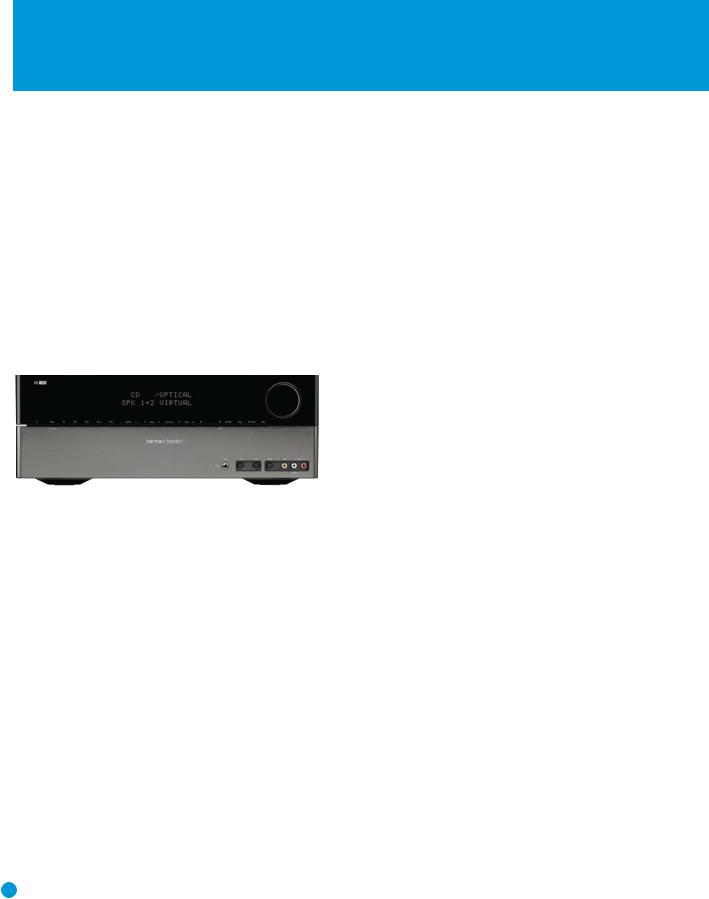
In the years since Harman Kardon invented the high-fidelity receiver, we have taken to heart the philosophy of bringing the joy of home entertainment to as many people as possible, all the while improving performance and adding features. The HK 3490 offers the best in traditional analog two-channel audio, including a 30-preset AM/FM tuner, an integrated phono preamplifier and a tape monitor loop that lets you listen to your tape recordings as they’re being made, while adding digital audio inputs, an XM Ready® tuner and a connection for The Bridge II docking station, which delivers audio playback and control for iPod, iPod touch and iPhone models (not included).
If high-performance audio reproduction weren’t enough, we’ve added composite video switching. Use the included audio/video cable to connect
your iPod or other portable player to the HK 3490, or just enjoy your favorite television programs in stereo without firing up your main home theater. Whether listening to an LP record pressed in the last century or watching a movie you downloaded to your digital media player last night, your new HK 3490 delivers the powerful, detailed performance you’ve come to expect from Harman Kardon.
To obtain the maximum enjoyment from your new receiver, we urge you to read this manual and refer back to it as you become more familiar with its features and their operation.
If you have any questions about this product, its installation or its operation, please contact your retailer or customer installer, or visit our Web site at www.harmankardon.com.
Harman Kardon® HK 3490 Stereo Receiver
Audio Section
•120 Watts x 2, both channels driven at full power at 8 ohms, 20Hz – 20kHz, <0.07% THD; 240 watts total
•150 Watts x 2, both channels driven at full power at 4 ohms, 20Hz – 20kHz, <0.2% THD; 300 watts total
•High-current capability, ultrawide-bandwidth amplifier design with low negative feedback
•All-discrete amplifier circuitry
Audio Inputs
• AM/FM/XM Ready* Tuner |
• Main-Amp Inputs |
• Phono |
• The Bridge II-Ready** Connector |
• CD |
• Coaxial and Optical Digital Audio Inputs |
• Tape-Monitor/CDR |
|
*XM antenna module and subscription to XM service required. Hardware and service sold separately. XM service is not available in Alaska or Hawaii.
**Compatible with all iPod models equipped with a dock connector. Not compatible with iPod shuffle models. No still-image or video playback.
Audio/Video Inputs (Composite Video)
• Video 1 |
• Video 3 (use frontor rear-panel connections) |
• Video 2/DVD |
|
Outputs
• Dual Subwoofer Outputs |
• Headphone |
• Tape/CDR |
• Two sets of Speaker Outputs for |
• Video 1 (Audio and Video) |
dual-room use |
• Video Monitor |
• Dual Subwoofer Trigger Outputs |
• Preamp Outputs |
|
Ease of Use
•Dot-matrix front-panel display
•Color-coded connections
•Seven-device system remote control
•Speaker 1/2 switching
•Rotary front-panel Tone Controls
•Remote IR Input and Output
•Energy-saving Subwoofer Link Switches
Supplied Accessories
The following accessory items are supplied with the HK 3490. If any of these items are missing, please contact Harman Kardon customer service at www.harmankardon.com.
• System remote control |
• Four AAA batteries |
• AM loop antenna |
• One 1/8" mini-plug-to-analog- |
• FM wire antenna |
audio/composite-video cable |
6

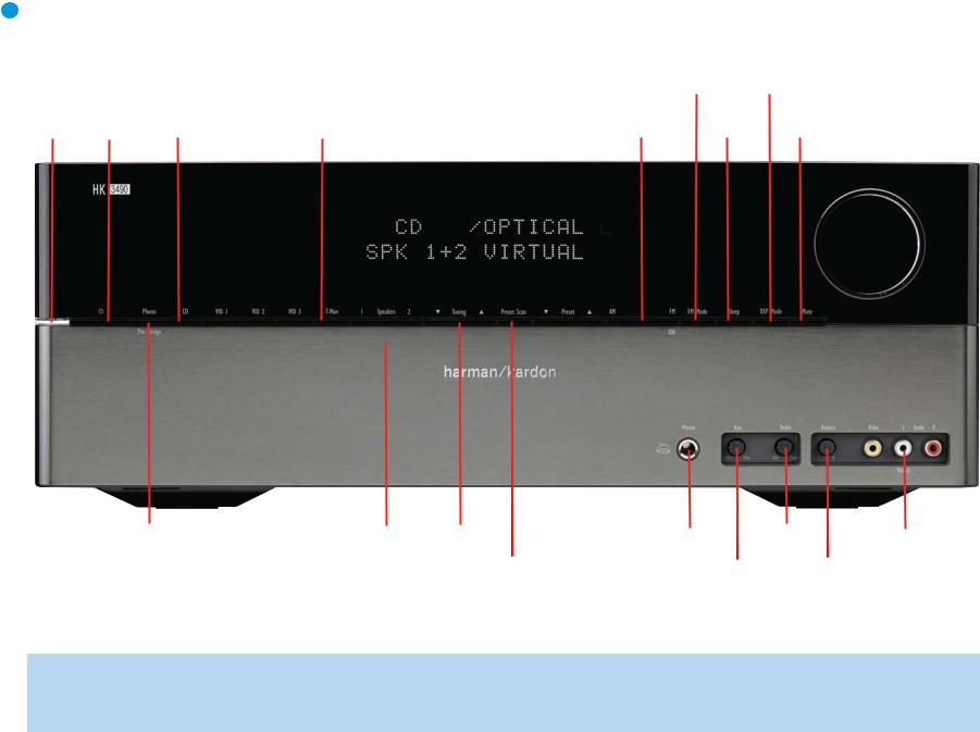
FRONT-PANEL CONTROLS
Power Indicator: This LED has two modes. When power is turned off, the LED is amber to indicate that the receiver is plugged in and ready to be turned on. When the receiver is turned on, the LED turns white.
Power Switch: This electrical switch turns the receiver on for playback, or leaves it in Standby mode for quick turn-on using the remote control.
Phono/The Bridge Source Selector: Press this button to select a turntable connected to the Phono Inputs as the source. Press it again to select an iPod docked in the optional Harman Kardon The Bridge II docking station as the source. Each additional press switches between these two sources.
CD Source Selector: Press this button to select the device connected to the CD Inputs as the source.
Video Source Selectors: Press any of these buttons to select the device connected to the corresponding Audio and Video Inputs for
playback. Remember to turn on the source device, to connect the Video Monitor Output to your video display and to turn on your video display and select the correct Video Input.
NOTE: The Video 3 source device may be connected to either the frontor rear-panel connectors. To select the desired device, press the Video 3 Source Selector repeatedly to toggle between the front and rear inputs.
Tape Source Selector: Press this button to select the device connected to the Tape/CDR Audio Inputs as the source. If you are making a recording using a three-head tape deck or another unit with off-head playback, you will be able to monitor the recording as it is being made.
Speaker 1/2: Press the left side of this button to enable the
HK 3490 to output audio to the speakers connected to the Speaker 1 Outputs, and press the right side of the button to enable the Speaker 2 Outputs. You may enable or disable both sets of speaker outputs simultaneously. This feature is a convenient way of hearing audio in more than one room at a time, although the same source material will be played through both sets of speakers.
Tuning: Press either side of this button to tune a radio station. Tap the button briefly to tune one frequency step at a time, or press and hold the button to seek the next frequency with an acceptably strong signal.
Preset Scan: Press this button once to scan through the stations you have previously programmed as presets. Each station will play for five seconds before the tuner skips to the next preset station. Press the button a second time to select the current station. If no presets have been programmed, the 0 PRESET message will be displayed. When listening to XM® Radio, each press displays the current playback information: channel name and number, category, artist and song title.
Preset Stations: Press this button to select a preset radio station. If no presets have been programmed, the 0 PRESET message will be displayed. When listening to XM Radio, each press changes the preset number within the current lettered bank.
Tuner Band: Press this button to select the tuner as the source, or to select the AM (left side of button) or FM (right side of button) band. Each press of the FM side of the button toggles between the FM and XM bands.
FM Mode: This button toggles between Stereo and Mono modes when an FM station is tuned. Mono mode may improve reception of weaker signals. When listening to XM radio, each press of this button changes the channel search mode as follows:
•All Channel Search: The Tuning Buttons and the ‹ / › Buttons on the remote may be used to tune any channel.
•Preset Search: The ‹ / › Buttons on the remote may be used to change the lettered bank of presets.
•Category Search: The Tuning Buttons and the ‹ / › Buttons on the remote may be used to tune a channel within the current category.
Sleep: Press this button to activate the sleep timer, which shuts off the receiver after a programmed period of time up to 90 minutes.
DSP Mode: Each press of this button switches the digital signal processing mode as follows: Dolby® Virtual Speaker Wide, Dolby Virtual Speaker Reference, Stereo.
Mute: Press this button to mute the HK 3490’s speaker and headphone outputs temporarily. To end the muting, press this button or adjust the volume. Muting is also canceled when the receiver is turned off.
Volume Control: Turn this knob to raise or lower the volume, which will be shown in decibels (dB) in the Message Display.
Headphone Jack: Plug a 1/4" headphone plug into this jack for private listening.
Bass Control: Turn the knob clockwise to boost low-frequency output by up to 10dB, or counterclockwise to cut low-frequency output by up to 10dB. Set the control to suit your taste and room acoustics.
Treble Control: Turn the knob clockwise to boost high-frequency output by up to 10dB, or counterclockwise to cut high-frequency output by up to 10dB. Set the control to suit your taste and room acoustics.
Balance Control: Turn the knob to adjust the relative volume of the left and right channels, which affects imaging and can compensate for room characteristics.
NOTE: To use the Bass, Treble or Balance Controls, gently press the knob until it unlatches. When finished, press the knob again to lock it.
Video 3 A/V Inputs: Connect a source component that will only be used temporarily to these jacks, such as a camera or game console, or connect an iPod using the supplied audio/video cable.
Message Display: Various messages appear in this display in response to commands. In normal use, the Upper Line will display the current source and audio input (analog or one of the digital audio inputs). The Lower Line displays the current speaker group (if any are active) and the DSP mode. Other messages may appear for some sources, such as The Bridge docking station and the tuner.
7
8
|
|
|
|
|
|
|
|
|
|
|
|
|
|
|
FM Mode |
DSP Mode |
|
|
|
|
||||||
Power |
Power |
CD Source |
|
|
Tape Source |
|
|
|
|
Tuner |
|
|
|
|
|
|
|
|
Volume |
|||||||
Indicator |
Switch |
Selector |
|
|
Selector |
Message Display |
Band |
|
|
Sleep |
|
|
Mute |
Control |
||||||||||||
|
|
|
|
|
|
|
|
|
|
|
|
|
|
|
|
|
|
|
|
|
|
|
|
|
|
|
|
|
|
|
|
|
|
|
|
|
|
|
|
|
|
|
|
|
|
|
|
|
|
|
|
|
|
|
|
|
|
|
|
|
|
|
|
|
|
|
|
|
|
|
|
|
|
|
|
|
|
|
|
|
|
|
|
|
|
|
|
|
|
|
|
|
|
|
|
|
|
|
|
|
|
|
|
|
|
|
|
|
|
|
|
|
|
|
|
|
|
|
|
|
|
|
|
|
|
|
|
|
|
|
|
|
|
|
|
|
|
|
|
|
|
|
|
|
|
|
|
|
|
|
|
|
|
|
|
|
|
|
|
|
|
|
|
|
|
|
|
|
|
|
|
|
|
|
|
|
|
|
|
|
|
|
|
|
|
|
|
|
|
|
|
|
|
|
|
|
|
|
|
|
|
|
|
|
|
|
|
|
|
|
|
|
|
|
|
|
|
|
|
|
|
|
|
|
|
|
|
|
|
|
|
|
|
|
|
|
|
|
|
|
|
|
Phono/The Bridge |
Video Source |
1 Speakers 2 |
Tuning |
Preset |
Headphone |
Treble |
Video 3 |
Source Selector |
Selectors |
|
|
Stations |
Jack |
Control |
|
|
|
A/V Inputs |
|||||
|
|
|
Preset Scan |
|
Bass |
|
Balance |
|
|
|
|
|
Control |
|
Control |
NOTE: To make it easier to follow the instructions throughout the manual that refer to this illustration, a copy of this page may be downloaded from the Product Support section at www.harmankardon.com.

REAR-PANEL CONNECTIONS
AM and FM Antenna Terminals: Connect the included AM and FM antennas to their respective terminals for radio reception.
Video 1, Video 2 and Video 3 Audio/Video Inputs: These jacks may be used to connect your video-capable source components (e.g., VCR, DVD player, cable TV box) to the receiver.
NOTE: The Video 3 source has inputs on both the front and rear panels of the HK 3490, and you may connect different devices to each set of inputs. To select between the two sets of inputs, press the Video 3 Source Selector repeatedly.
Video 1 Audio/Video Outputs: These jacks may be used to connect your VCR or another recorder.
Video Monitor Output: If some of your sources use video connections, connect the Video Monitor Output to the corresponding input on your television or video display to view the sources. No video signal will be available when an audio-only source input, such as CD or Tape, is selected.
Remote Infrared (IR) Input and Output: When the remote IR receiver on the front panel is blocked, such as when the HK 3490
is placed inside a cabinet, connect an optional IR receiver to the Remote IR Input jack for use with the remote control. The Remote IR Output may be connected to the Remote IR Input of a compatible source device
(or other product) to enable remote control through the HK 3490. When several source devices are used, connect them in “daisy chain” fashion.
Update Port: This connection is for authorized service personnel only. It is used with a proprietary device in the event that a software update for the HK 3490 becomes available in the future. Do not make any connections to it.
Reset Button: In the event that the HK 3490 operates erratically, a system reset may restore proper functionality. Place the unit in Standby mode by pressing the Power Switch so that the Power Indicator turns amber. Then use a fine-point pen or other similar object to press the Reset Button.
The Bridge/DMP Input: Connect the optional Harman Kardon
 or
or  docking station to this input for use with
your iPod, iPod touch or iPhone (not included). Make sure the receiver is turned off (in Standby mode) when connecting The Bridge or
The Bridge II docking station.
XM Antenna Jack: Plug in an XM antenna module here. The XM antenna module is purchased separately, and should specify that it is for home use with an XM Ready product. You will need to subscribe to the XM service, which is available separately, and activate the service for your antenna module. (XM service is not available in Alaska and Hawaii.)
Coaxial and Optical Digital Audio Inputs: If a source has a compatible digital audio output, connect it to one of these jacks for improved audio performance. Use only one type of digital audio connection for each source.
AC Power Cord: After you have made all other connections, plug the AC power cord into an unswitched outlet.
Switched AC Accessory Outlets: You may plug the AC power cord of one source device into each of these outlets, and it will turn on whenever you turn on the receiver. Do not use sources that consume more than 100 watts of power per outlet.
Speaker 1 and 2 Outputs: Use two-conductor speaker wire to connect each set of terminals to the correct speaker. Observe the correct polarity (positive and negative connections). Always connect the positive lead to the red or white terminal on the receiver and the red terminal on the speaker. Connect the negative lead to the black terminal on both the receiver and the speaker. Use the Speaker 1/2 Selectors on the front panel or remote to select either or both pairs of speakers for playback.
Subwoofer Outputs: If you have a powered subwoofer, connect these jacks to the line-level inputs on the subwoofer. The same fullrange signal is output through both jacks. Thus, you have the option
of connecting each jack to the line-level input on a separate subwoofer or to use the full-range outputs to feed a remote room in a distributedaudio application. If you have only one subwoofer with a single line-level input, connect it to the right Subwoofer Output on the HK 3490.
Subwoofer Trigger Outputs: Connect these outputs to a compatible trigger input on the subwoofer connected to the Subwoofer Output immediately to the right of the Trigger Output. Consult the owner’s manual for the subwoofer to set its trigger input correctly, and the subwoofer will automatically turn on or off when the HK 3490 is turned on or off. In addition, the Trigger Outputs are used with the Subwoofer Link Switches to conserve energy by powering off the subwoofer’s amplifier when it is not needed. The Subwoofer Trigger Outputs send a signal of 15 volts DC.
Subwoofer Link Switches: Each switch affects the subwoofer connected to the jack immediately to the left of the switch. To use the switch, first connect the corresponding Subwoofer Trigger Output to a compatible trigger input on the subwoofer, and make sure the
subwoofer’s instructions are followed to activate its trigger input. When the Link Switch is on, the HK 3490 will remove the trigger signal whenever the corresponding pair of main speakers is not in use, thereby conserving energy that would otherwise be used to maintain the subwoofer’s amplifier in Standby mode. This feature is activated any time no signal is present at the main speaker outputs, including when the Speaker 1/2 Switch turns off both speaker pairs, when the HK 3490’s output is muted, or when the headphones are plugged in. See Table A2 in the appendix for details.
Main-Amp Inputs and Preamp Outputs: These jacks are normally connected directly to each other with an included jumper. Some devices, such as equalizers and some loudspeaker systems, require connection between the Preamp Outputs and Main-Amp Inputs, in which case the jumpers should be removed and stored in a safe place for future use. You may also remove the jumpers if you wish to connect the Preamp Outputs to an external amplifier, or if you wish to connect another device’s line-level output directly to the HK 3490’s power amplifier for a special application.
Tape Outputs: These jacks may be used to connect your CDR or another audio-only recorder.
9 |
9 |

10
|
|
|
|
|
|
|
|
|
|
|
|
|
|
|
|
|
Video 1 |
Video 2/ |
Video |
Remote |
|
|
|
|
|
|
|
|
|||||||||||||||
|
|
|
|
|
|
|
|
|
|
|
|
|
|
|
|
|
A/V |
|
|
|
|
DVD |
Monitor |
IR |
|
|
|
|
|
|
|
|
|||||||||||
|
|
|
|
|
AM Antenna |
Tape/CDR |
Inputs |
Inputs |
Output |
Output |
Reset |
||||||||||||||||||||||||||||||||
Phono |
|
|
Inputs |
|
|
|
Video 1 |
|
|
|
Video 3 |
Remote |
|
|
|
Button |
|||||||||||||||||||||||||||
|
|
|
|
|
|
|
|
|
|
|
|
|
|
|
|
|
|
|
|
|
|
|
|
|
|
|
|
|
|
|
|
||||||||||||
|
FM Antenna |
|
|
CD |
|
|
Tape/CDR |
|
A/V |
|
|
|
A/V |
|
IR |
|
Update |
|
|
|
|
|
|
AC Power |
|||||||||||||||||||
|
|
|
Inputs |
Outputs |
|
|
|
Outputs |
|
|
|
Inputs |
Input |
|
Port |
|
|
|
|
|
|
Cord |
|||||||||||||||||||||
|
|
|
|
|
|
|
|
|
|
|
|
|
|
|
|
|
|
|
|
|
|
|
|
|
|
|
|
|
|
|
|
|
|
|
|
|
|
|
|
|
|
|
|
|
|
|
|
|
|
|
|
|
|
|
|
|
|
|
|
|
|
|
|
|
|
|
|
|
|
|
|
|
|
|
|
|
|
|
|
|
|
|
|
|
|
|
|
|
|
|
|
|
|
|
|
|
|
|
|
|
|
|
|
|
|
|
|
|
|
|
|
|
|
|
|
|
|
|
|
|
|
|
|
|
|
|
|
|
|
|
|
|
|
|
|
|
|
|
|
|
|
|
|
|
|
|
|
|
|
|
|
|
|
|
|
|
|
|
|
|
|
|
|
|
|
|
|
|
|
|
|
|
|
|
|
|
|
|
|
|
|
|
|
|
|
|
|
|
|
|
|
|
|
|
|
|
|
|
|
|
|
|
|
|
|
|
|
|
|
|
|
|
|
|
|
|
|
|
|
|
|
|
|
|
|
|
|
|
|
|
|
|
|
|
|
|
|
|
|
|
|
|
|
|
|
|
|
|
|
|
|
|
|
|
|
|
|
|
|
|
|
|
|
|
|
|
|
|
|
|
|
|
|
|
|
|
|
|
|
|
|
|
|
|
|
|
|
|
|
|
|
|
|
|
|
|
|
|
|
|
|
|
|
|
|
|
|
|
|
|
|
|
|
|
|
|
|
|
|
|
|
|
|
|
|
|
|
|
|
|
|
|
|
|
|
|
|
|
|
|
|
|
|
|
|
|
|
|
|
|
|
|
|
|
|
|
|
|
|
|
|
|
|
|
|
|
|
|
|
|
|
|
|
|
|
|
|
|
|
|
|
|
|
|
|
|
|
|
|
|
|
|
|
|
|
|
|
|
|
|
|
|
|
|
|
|
|
|
|
|
|
|
|
|
|
|
|
|
|
|
|
|
|
|
|
|
|
|
|
|
|
|
|
|
|
|
|
|
|
|
|
|
|
|
|
|
|
|
|
|
|
|
|
|
|
|
|
|
|
|
|
|
|
|
|
|
|
|
|
|
|
|
|
|
|
|
|
|
|
|
|
|
|
|
|
|
|
|
|
|
|
|
|
|
|
|
|
|
|
|
|
|
|
|
|
|
|
|
|
|
|
|
|
|
|
|
|
|
|
|
|
|
|
|
|
|
|
|
|
|
|
|
|
|
|
|
|
|
|
|
|
|
|
|
|
|
|
|
|
|
|
|
|
|
|
|
|
|
|
|
|
|
|
|
|
|
|
|
|
|
|
|
|
|
|
|
|
|
|
|
|
|
|
|
|
|
|
|
|
|
|
|
|
|
|
|
|
|
|
|
|
|
|
|
|
|
|
|
|
|
|
|
|
|
|
|
|
|
|
|
|
|
|
|
|
|
|
|
|
|
|
|
|
|
|
|
|
|
|
|
|
|
|
|
|
|
|
|
|
|
|
|
|
|
|
|
|
|
|
Subwoofer |
Subwoofer |
Main-Amp |
Speaker 2 |
|
Switched AC |
Main |
Trigger |
Link |
Inputs |
Outputs |
XM Antenna |
Accessory |
Power |
Outputs |
Switches |
|
|
Jack |
Outlets |
Switch |
Subwoofer |
Preamp |
Speaker 1 |
The Bridge |
Digital |
|
|
Outputs |
Outputs |
Outputs |
DMP Connector |
Audio Inputs |
|
|
NOTE: To make it easier to follow the instructions throughout the manual that refer to this illustration, a copy of this page may be downloaded from the Product Support section at www.harmankardon.com.
 Loading...