


®
®
Power for the Digital Revolution.
DPR 2005
DIGITAL PATH RECEIVER
OWNER’S MANUAL

DPR 2005 DIGITAL PATH RECEIVER
3Introduction
4Important Safety Information
4Unpacking
5Front-Panel Controls
8 Rear-Panel Connections
11 Main Remote Control Functions
15Zone II Remote Control Functions
16Installation and Connections
19System Configuration
19Speaker Placement
19System Setup
20Input Setup
22 Audio Setup
22 Surround Setup
24 Speaker Setup
26Delay Settings
27Output Level Adjustment
27Using EzSet
28Manual Output Level Adjustment
30Operation
30Basic Operation
30Source Selection
306/8-Channel Direct Input
30Volume and Tone Control
31Surround Mode Selection
31Digital Audio Playback
32Surround Mode Chart
35Tuner Operation
35Tape Recording
35Front-Panel Connections
36Output Level Trim Adjustment
37Advanced Features
37Front-Panel Display Fade
37Display Brightness
37Turn-On Volume Level
37Semi-OSD Settings
38Full-OSD Time-Out Adjustment
39Multiroom Operation
39 Multiroom Setup
39Surround Amplifier Channel Assignment
40Multiroom Operation
41Configuring the Remote
41 Programming Remote Codes
41Preprogrammed Code Entry
42Automatic Code Entry
42Learning Commands
43Changing Devices
44Macro Programming
46Punch-Through Configuration
47EzSet Configuration
48Renaming
49Resetting the Remote
51Troubleshooting Guide
51Processor Reset
52Technical Specifications
See trademark acknowledgements on page 52.
Typographical Conventions
In order to help you use this manual with the remote control, front-panel controls and rear-panel connections, certain conventions have been used.
EXAMPLE – (bold type) indicates a specific remote control or front-panel button, or rear-panel connection jack
EXAMPLE – (OCR type) indicates a message that is visible on-screen or on the front-panel information display
EXAMPLE – (Synchro type) indicates a message that is displayed on the remote control’s LCD screen
1 – (number in a square) indicates a specific front-panel control
A – (letter in a square) indicates a front-panel control that is behind the drop-down door
¡ – (number in a circle) indicates a rear-panel connection
a – (number in an oval) indicates a button or indicator on the remote
å – (letter in an oval) indicates a button on the Zone II remote
2 TABLE OF CONTENTS
INTRODUCTION
Thank You for Choosing Harman Kardon®
With the purchase of a Harman Kardon DPR 2005, you are about to begin many years of listening enjoyment. Thanks to its completely digital path system, the DPR 2005 is truly a receiver for the new millennium. The DPR 2005 has a wide range of features and options that accommodate virtually any combination of speakers, room size and program sources. It is
as easy to operate as it is to set up, but in order to take maximum advantage of the many advanced technologies within your new DPR, it is strongly recommended that you take a few minutes to read this owner’s manual.
If you have any questions about this product, its installation or its operation, we recommend that you contact your dealer or installer, as they are your best source of local information. You may also access a wealth of information and assistance by visiting our Web site
at www.harmankardon.com.
Description and Features
Harman Kardon’s breakthrough Digital Path Receiver technology, of which the DPR 2005 is the second generation, keeps signals in the digital domain from the input to the output. Along with the newly designed PWM digital amplifier, this not only reduces signal degradation caused by digital-to-analog conversion stages; the increased efficiency makes it possible to reduce the DPR’s size and weight without sacrificing performance.
The DPR 2005 is designed to serve as the hub of your home entertainment system, providing a variety of listening options. When playing movies or other programming from digital formats such as DVD or HDTV, the DPR decodes Dolby* Digital, Dolby Digital EX, DTS® and DTS-ES.® Two-channel stereo and matrix surround sources benefit from the new Pro Logic IIx technology and DTS Neo:6.® A Harman Kardon exclusive in receivers is the latest version of Logic 7® to create a wider, more enveloping sound field and more defined surround channel positioning, regardless of the type of source material. Additional processing options include MP3 decoding when connected to a compatible computer and HDCD® for enhanced CD playback. Advanced technology is also at work even when only two speakers are used. Dolby Virtual Speaker modes and Harman International’s proprietary VMAx® are both available to create enveloping sound fields from the front left and right speakers, while Dolby Headphone circuitry creates an amazing sense of openness with headphones.
Along with the many listening options, the DPR 2005 offers numerous settings that let you customize the system. A Quadruple Crossover bass management system configures each speaker group for a different crossover setting, while the assignable, wide bandwidth component video inputs may be linked to any video source. To further enhance the viewing experience with digital video sources or advanced digital video displays, the DPR 2005’s A/V Sync Delay feature allows you to compensate for the loss of lip sync common in many video processing systems by delaying the audio signal independently for each input. An advanced version of Harman Kardon’s patented EzSet remote completes the package, making it easier than ever to set system output levels and to program the remote to operate virtually any program source.
The DPR 2005’s multizone options and a standard Zone II remote control make it possible to listen to a separate source in one room while the main home theater uses a different source. Thanks to assignable rear surround channel amplifiers, you may create a basic remote listening zone without any additional equipment. The unit’s Multiroom outputs may also be used to feed an optional, external power amplifier and volume control. For one-wire multiroom connectivity, the DPR 2005 is A-BUS Ready,® requiring only a single Category 5/5e cable and an optional remote module to power remote speakers while controlling volume and enabling full control over the program source and compatible IR-controlled devices.
Combining state-of-the-art circuitry, digital technology and proven performance with an elegant design that is compatible with the latest source components and video displays, the DPR 2005 represents the culmination of Harman Kardon’s 50-year history of delivering the finest sonic performance.
For Canadian model
This class B digital apparatus complies with Canadian ICES-003.
For models having a power cord with a polarized plug: CAUTION: To prevent electric shock, match wide blade of plug to wide slot, fully insert.
Modèle pour les Canadien
Cet appareil numérique de la classe B est conforme à la norme NMB-003 du Canada.
Sur les modèles dont la fiche est polarisee: ATTENTION: Pour éviter les chocs électriques, introduire la lame la plus large de la fiche dans la borne correspondante de la prise et pousser jusqu’au fond.
■All popular digital and matrix surround modes, including Dolby* Digital, Dolby Digital EX, Dolby Pro Logic* IIx, DTS,® DTS-ES® Discrete and Matrix, DTS Neo:6® and DTS 96/24
■Harman Kardon’s exclusive Logic 7® processing, along with a choice of either Dolby Virtual Speaker or VMAx® processing for use when only two speakers are available
■Dolby Headphone to create spacious, open sound fields when using headphones
■HDCD® decoding for enhanced CD playback, and MP3 decoding for use with compatible computers
■High-bandwidth, HDTV-compatible component video inputs may be assigned to any video input
■Full bass management for all inputs, including the analog direct inputs for DVD-Audio and SACD players, including Quadruple Crossover and individual settings for each input
■A/V Sync delay adjustable for each input delivers perfect lip sync with digital programs or video displays
■Front-panel digital audio and analog audio/ video jacks may be used as either inputs or outputs for connection to portable products or video game consoles
■Extensive Multiroom options, including a standard Zone II remote, assignable rearchannel amplifier channels and A-BUS Ready® capability for listening to a separate source in a remote zone
■Easy-to-program 


 remote with twoline LCD display automatically sets output levels for optimal performance
 ®, HDCD®, High Definition Compatible Digital® and Pacific Microsonics™ are either registered trademarks or trademarks of Pacific Microsonics, Inc., in the United States and/or other countries. HDCD system manufactured under license from Pacific Microsonics, Inc.
INTRODUCTION 3

SAFETY INFORMATION
Important Safety Information
Verify Line Voltage Before Use
Your DPR 2005 has been designed for use with 120-volt AC current. Connection to a line voltage other than that for which it is intended can create a safety and fire hazard and may damage the unit.
If you have any questions about the voltage requirements for your specific model, or about the line voltage in your area, contact your selling dealer before plugging the unit into a wall outlet.
Do Not Use Extension Cords
To avoid safety hazards, use only the power cord attached to your unit. We do not recommend that extension cords be used with this product. As with all electrical devices, do not run power cords under rugs or carpets or place heavy objects on them. Damaged power cords should be replaced immediately by an authorized service center with a cord meeting factory specifications.
Handle the AC Power Cord Gently
When disconnecting the power cord from an AC outlet, always pull the plug; never pull the cord. If you do not intend to use the unit for any considerable length of time, disconnect the plug from the AC outlet.
Do Not Open the Cabinet
There are no user-serviceable components inside this product. Opening the cabinet may present a shock hazard, and any modification to the product will void your guarantee. If water or any metal object such as a paper clip, wire or a staple accidentally falls inside the unit, disconnect it from the AC power source immediately, and consult an authorized service center.
CATV or Antenna Grounding
If an outside antenna or cable system is connected to this product, be certain that it is grounded so as to provide some protection against voltage surges and static charges. Section 810 of the National Electrical Code, ANSI/NFPA No. 70-1984, provides information with respect to proper grounding of the mast and supporting structure, grounding of the lead-in wire to an antenna discharge unit, size of grounding conductors, location of antenna discharge unit, connection to grounding electrodes and requirements of the grounding electrode.
NOTE TO CATV SYSTEM INSTALLER: This reminder is provided to call the CATV (Cable TV) system installer’s attention to article 820-40 of the NEC that provides guidelines for proper grounding and, in particular, specifies that the cable ground shall be connected to the grounding system of the building, as close to the point of cable entry as possible.
Installation Location
■To ensure proper operation and to avoid the potential for safety hazards, place the unit on a firm and level surface. When placing the unit on a shelf, be certain that the shelf and any mounting hardware can support the weight of the product.
■Make certain that proper space is provided both above and below the unit for ventilation. If this product will be installed in a cabinet or other enclosed area, make certain that there is sufficient air movement within the cabinet. Under some circumstances, a fan may be required.
■Do not place the unit directly on a carpeted surface.
■Avoid installation in extremely hot or cold locations, or in an area that is exposed to direct sunlight or heating equipment.
■Avoid moist or humid locations.
■Do not obstruct the ventilation slots on the top of the unit, or place objects directly over them.
■There is the remote possibility that the rubber padding on the bottom of the unit’s feet may leave marks on certain wood or veneer materials. Use caution when placing the unit on soft woods or other materials that may be damaged by heat or heavy objects.
Cleaning
When the unit gets dirty, wipe it with a clean, soft, dry cloth. If necessary, wipe it with a soft cloth dampened with mild soapy water, then a fresh cloth with clean water. Wipe dry immediately with a dry cloth. NEVER use benzene, aerosol cleaners, thinner, alcohol or any other volatile cleaning agent. Do not use abrasive cleaners, as they may damage the finish of metal parts. Avoid spraying insecticide near the unit.
Moving the Unit
Before moving the unit, be certain to disconnect any interconnection cords with other components, and make certain that you disconnect the unit from the AC outlet.
Important Information for the User
This equipment has been tested and found to comply with the limits for a Class-B digital device, pursuant to Part 15 of the FCC Rules. The limits are designed to provide reasonable protection against harmful interference in a residential installation. This equipment generates, uses and can radiate radio-frequency energy and, if not installed and used in accordance with the instructions, may cause harmful interference to radio communication. However, there is no guarantee that harmful interference will not occur in a particular installation. If this equipment does cause harmful interference to radio or television reception, which can be
determined by turning the equipment off and on, the user is encouraged to try to correct the interference by one or more of the following measures:
■Reorient or relocate the receiving antenna.
■Increase the separation between the equipment and receiver.
■Connect the equipment into an outlet on a circuit different from that to which the receiver is connected.
■Consult the dealer or an experienced radio/TV technician for help.
This device complies with Part 15 of the FCC Rules. Operation is subject to the following two conditions:
(1) this device may not cause harmful interference, and (2) this device must accept interference received, including interference that may cause undesired operation.
NOTE: Changes or modifications may cause this unit to fail to comply with Part 15 of the FCC Rules and may void the user’s authority to operate the equipment.
Unpacking
The carton and shipping materials used to protect your new receiver during shipment were specially designed to cushion it from shock and vibration. We suggest that you save the carton and packing materials for
use in shipping if you move, or should the unit ever need repair.
To minimize the size of the carton in storage, you may wish to flatten it. This is done by carefully slitting the tape seams on the bottom and collapsing the carton. Other cardboard inserts may be stored in the same manner. Packing materials that cannot be collapsed should be saved along with the carton in a plastic bag.
If you do not wish to save the packaging materials, please note that the carton and other sections of the shipping protection are recyclable. Please respect the environment and discard those materials at a local recycling center.
At this time you should remove the protective plastic film from the front-panel lens. Leaving the film in place will affect the performance of your remote control.
4 SAFETY INFORMATION
FRONT-PANEL CONTROLS
( * & ^ |
% $ |
# |
||||||
|
|
|
|
|
|
|
|
|
|
|
|
|
|
|
|
|
|
|
|
|
|
|
|
|
|
|
1 2 |
3 4 5 6 7 8 9 |
) |
! @ |
A |
B C D E F G HIJ I K |
|
|
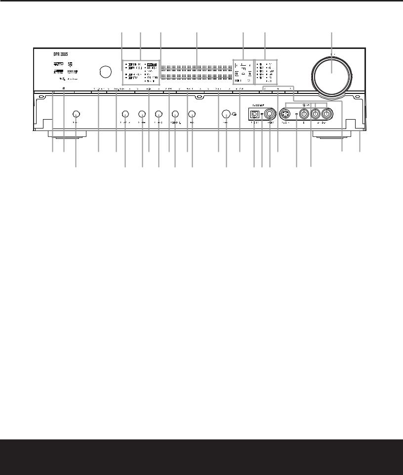
NOTE: To make it easier to follow the instructions that refer to this illustration, a larger copy may be downloaded from the Product Support section for this product at www.harmankardon.com.
The following controls and indicators are available on the DPR 2005’s front panel:
1 Standby/On Indicator |
8 Input Source Selector |
% Speaker/Channel Input Indicators |
2 Standby/On Button |
9 Tuning Mode Selector |
^ Upper Display Line |
3 Surround Mode Group Selector |
) Set Button |
& Lower Display Line |
4 Surround Mode Selector |
! ¤/⁄ Buttons |
* Surround Mode Indicators |
5 Tuning Selector |
@ Front-Panel Control Door |
( Remote Sensor Window |
6 Tuner Band Selector |
# Volume Control |
|
7 Preset Station Selector |
$ Input Indicators |
|
The following controls and jacks are located behind the front-panel door. To open the door, press the center of the door and gently swing it down towards you.
A Main Power Switch |
E Digital Input Selector |
I Input/Output Indicators |
B Tone Mode Button |
F Delay Adjust Selector |
J Coaxial 3 Digital Jack |
C Speaker Selector Button |
G Headphone Jack |
K Video 5 Audio/Video Jacks |
D Channel Adjust Selector |
H Optical 3 Digital Input |
|
1 Standby/On Indicator: This indicator is amber when the DPR is in the Standby mode to signal that the unit is connected to an AC power source and is ready to be put into operation. When the unit is in use, the indicator turns blue.
2 Standby/On Button: When the Main Power Switch A is “ON,” press this button to turn on the DPR 2005; press it again to turn the unit off.
3 Surround Mode Group Selector: Press this button to select the top-level group of surround modes. Each press of the button will select one of the surround mode categories. Once the button is pressed so that the name of the desired surround mode category appears in the on-screen display and in the Lower Display Line &, press the Surround Mode Selector 4 to cycle through the individual modes available. For example, press this button to select Dolby
modes, and then press the Surround Mode Selector
4to choose from the various mode options.
4Surround Mode Selector: Press this button to select from among the available surround mode options for the surround mode category selected.
The specific modes will vary based on the number of speakers available, the surround mode category and whether the input source is digital or analog. For example, press the Surround Mode Group Selector 3
FRONT-PANEL CONTROLS 5

FRONT-PANEL CONTROLS
to select a category such as Dolby or Logic 7, and then press this button to see the specific mode choices that are available. For more information on mode selection, see page 32.
5 Tuning Selector: Press the left side of the button to tune lower-frequency stations and the right side of the button to tune higher-frequency stations. When
the tuner is in the MANUAL/MONO mode, each tap of the Selector will increase or decrease the frequency by one increment. When the tuner receives a strong-enough signal for adequate reception, MANUAL TUNED will appear in the Lower Display Line & and in the on-screen display. When the tuner is in the AUTO/STEREO mode, press the button once, and the tuner will scan for a station with acceptable signal strength. When the next higher or lower frequency station with a strong-enough signal is tuned, the frequency scan will stop and the Lower Display Line & and the on-screen display will indicate AUTO TUNED. When an FM Stereo station is tuned, the display will read AUTO ST TUNED. See page 35 for more information on using the tuner.
6 Tuner Band Selector: Pressing this button will automatically switch the DPR 2005 to the Tuner mode. Pressing it again will switch between the AM and FM frequency bands. (See page 35 for more information on the tuner.)
7 Preset Stations Selector: Press this button to scroll up or down through the list of stations that have been entered into the preset memory. (See page 35 for more information on tuner programming.)
8 Input Source Selector: Press this button to change the input by scrolling up or down through the list of input sources.
9 Tuning Mode Selector: Press this button to select Auto or Manual tuning. When the button is pressed so that AUTO/STEREO appears in the Upper Display Line ^, the tuner will search for the next station with an acceptable signal when the Tuning Selector 5wé is pressed. When the button is pressed so that MANUAL/MONO appears in the
Upper Display Line ^, each press of the Tuning Selector 5wé will increase the frequency. (See page 35 for more information on using the tuner.) This button may also be used to switch between Stereo and Mono modes for FM radio reception. When weak reception is encountered, select the Manual/Mono tuning mode. Press and hold again to switch back to
Stereo mode. (See page 35 for more information on using the tuner.)
) Set Button: When making system configuration changes using the front-panel controls, press this button to enter a setting into the unit’s memory.
! ¤/⁄ Buttons: When making system configuration changes using the front-panel controls, press these buttons to scroll through the available choices for the option being adjusted.
@ Front-Panel Control Door: To open the door so that the front-panel jacks and controls behind this door may be accessed, press the center of the door and gently swing it down towards you.
# Volume Control: Turn this knob clockwise to increase the volume, counterclockwise to decrease the volume. If the DPR 2005 is muted, adjusting the volume control will automatically release the unit from the silenced condition.
$ Input Indicators: One of these indicators will light to identify the currently selected input. Note that the entire list will light briefly each time the unit is turned on as a test.
% Speaker/Channel Input Indicators: These indicators are multipurpose, indicating both the speaker type selected for each channel and the incoming datasignal configuration. The left, center, right, right surround and left surround speaker indicators light as a single outline around the speaker position indicator when a “small” speaker is selected and as a larger icon with three connected boxes when “large” speakers are selected. When only the speaker position letters appear, no speaker has been assigned that position. (See page 24 for more information on configuring speakers.) The letters inside each box also indicate the active input channels. For standard analog inputs, only the L and R will light, indicating a stereo input. For a digital source, the indicators will light to display the channels being received at the digital input. When the letters flash, the digital input has been interrupted and an UNLOCK message may appear in the Lower Display Line &. (See page 34 for more information on the Channel Indicators.)
^ Upper Display Line: Depending on the unit’s status, a variety of messages will appear here. In normal operation, this line will show the current input source and identify whether an analog or digital input is in use. When the tuner is selected as the input, this line will identify the station as AM or FM and show the
frequency and preset number, if any.
& Lower Display Line: Depending on the unit’s status, a variety of messages will appear here. In normal operation, the current surround mode will appear on this line.
* Surround Mode Indicators: One of these indicators will light to show the surround mode in use. Depending on the specific combination of input sources and surround mode selected, more than one indicator may light. (See page 33 for more information.)
( Remote Sensor Window: The sensor behind this window receives infrared signals from the remote control. Aim the remote at this area and do not block or cover it unless an external remote sensor is installed.
6 FRONT-PANEL CONTROLS

FRONT-PANEL CONTROLS
A B C D E F G H I J I K
NOTE: To make it easier to follow the instructions that refer to this illustration, a larger copy may be downloaded from the Product Support section for this product at www.harmankardon.com.
The following controls and jacks are located behind the front-panel door. To open the door, press the center of the door and gently swing it down towards you.
AMain Power Switch B Tone Mode Button
C Speaker Selector Button D Channel Adjust Selector
AMain Power Switch: Press this switch to apply power to the DPR 2005. When the switch is pressed in, the unit is placed in a Standby mode, as indicated by the Standby/On Indicator 1 turning amber. The switch MUST be pressed in to operate the unit. To turn the unit off and prevent the use of the remote control, this switch should be pressed until it pops out from the front panel so that the word “OFF” may be read at the top of the switch.
NOTE: This switch is normally left in the “ON” position.
B Tone Mode Button: This button controls the tone mode settings, enabling adjustment of the bass and treble boost/cut. You may also use it to take the tone controls out of the signal path completely for “flat” response. The first press of the button displays a TONE MODE message in the Lower Display Line & and in the on-screen display. To take the controls out of the signal path, press either of the ¤/⁄ Buttons ! until the display reads TONE OUT. To change the bass or treble settings, press the button again until the desired option appears in the Lower Display Line & and in the on-screen display and then press either of the ‹/› Buttons ! to enter the desired boost or cut setting. See page 30 for more information on the tone controls.
C Speaker Selector Button: Press this button to begin the process of configuring the DPR 2005 for the type of speakers it is being used with. For complete information on configuring the speaker settings, see page 24.
E Digital Input Selector
F Delay Adjust Selector
G Headphone Jack
H Optical 3 Digital Input
D Channel Adjust Selector: Press the button to begin the process of adjusting the channel level outputs using the source currently playing through your DPR. For complete information on adjusting the channel output level, see page 36.
E Digital Input Selector: Press this button to begin the process of selecting a digital source for use with the currently selected input. Once the button has been pressed, use the ¤/⁄ Buttons ! to choose the desired input and then press the Set Button ) to enter the setting into the unit’s memory. See page 31 for more information on digital audio.
F Delay Adjust Selector: Press this button to begin the process of adjusting the delay settings for Dolby surround modes. See page 26 for more information on delay adjustments.
G Headphone Jack: This jack may be used to listen to the DPR 2005’s output through a pair of headphones. Be certain that the headphones have a standard 1/4" stereo phone plug, or that you use an adapter, as needed, to convert the plug on your headphones to the 1/4" jack used on the AVR. When the headphone jack is in use, the main room speakers will automatically be turned off and the unit will output a standard stereo signal. You may also use one of the Dolby Headphone modes for an enhanced listening experience. For more information on headphone listening, see page 31.
I Input/Output Indicators
J Coaxial 3 Digital Jack
K Video 5 Audio/Video Jacks
H Optical 3 Digital Input: Connect the optical digital output of an audio or video product to this jack.
I Input/Output Status Indicators: These LED indicators will normally light green to show that the frontpanel Coaxial 3 Digital Jack J and Video 5 Input/Output Jacks K are operating as inputs. When these jacks are configured for use as an output, the appropriate indicator will turn red to show that the jack may be used as an output for recording. (See page 35 for more information on configuring the front-panel jacks as outputs, rather than inputs.)
J Coaxial 3 Digital Jack: Connect the coaxial digital input or output for a digital audio product such as a portable audio player or video game to this jack. The jack is normally an input, but may be switched to an output for recording using the menu system. See page 35 for more information.
K Video 5 Input/Output Jacks: These audio/video jacks may be used as either an input or output for temporary connection to video games or portable audio/video products such as camcorders and portable audio players. (See page 35 for more information on switching these jacks between an input and output.)
FRONT-PANEL CONTROLS 7

REAR-PANEL CONNECTIONS
|
35 |
|
33 31 |
|
|
|
|
|
|
j |
|
|
h |
|
|
f |
|
|
|
d |
|||||||||||||||||
|
36 |
|
|
|
34 32 |
|
|
|
|
|
k i |
|
|
|
|
g |
|
|
|
|
|
e |
|
|
|
|
c |
||||||||||
|
|
|
|
|
|
|
|
|
|
|
|
|
|
|
|
|
|
|
|
|
|
|
|
|
|
|
|
|
|
|
|
|
|
|
|
|
|
|
|
|
|
|
|
|
|
|
|
|
|
|
|
|
|
|
|
|
|
|
|
|
|
|
|
|
|
|
|
|
|
|
|
|
|
|
|
|
|
|
|
|
|
|
|
|
|
|
|
|
|
|
|
|
|
|
|
|
|
|
|
|
|
|
|
|
|
|
|
|
|
|
|
|
|
|
|
|
|
|
|
|
|
|
|
|
|
|
|
|
|
|
|
|
|
|
|
|
|
|
|
|
|
|
|
|
|
|
|
|
|
|
|
|
|
|
|
|
|
|
|
|
|
|
|
|
|
|
|
|
|
|
|
|
|
|
|
|
|
|
|
|
|
|
|
|
|
|
|
|
|
|
|
|
|
|
|
|
|
|
|
|
|
|
|
|
|
|
|
|
|
|
|
|
|
|
|
|
|
|
|
|
|
|
|
|
|
|
|
|
|
|
|
|
|
|
|
|
|
|
|
|
|
|
|
|
|
|
|
|
|
|
|
|
|
|
|
|
|
|
|
|
|
|
|
|
|
|
|
|
|
|
|
|
|
|
|
|
|
|
|
|
|
|
|
|
|
|
|
|
|
|
|
|
|
|
|
|
|
|
|
|
|
|
|
|
|
|
|
|
|
|
|
|
|
|
|
|
|
|
|
|
|
|
|
|
|
|
|
|
|
|
|
|
|
|
|
|
|
|
|
|
|
|
|
|
|
|
|
|
|
|
|
|
|
|
|
|
|
|
|
|
|
|
|
|
|
|
|
|
|
|
|
|
|
|
|
|
|
|
|
|
|
|
|
|
|
|
|
|
|
|
|
|
|
|
|
|
|
|
|
|
|
|
|
|
|
|
|
|
|
|
|
|
|
|
|
|
|
|
|
|
|
|
|
|
|
|
|
|
|
|
|
|
|
|
|
|
|
|
|
|
|
|
|
|
|
|
|
|
|
|
|
|
|
|
|
|
|
|
|
|
|
|
|
|
|
|
|
|
|
|
|
|
|
|
|
|
|
|
|
|
|
|
|
|
|
|
|
|
|
|
|
|
|
|
|
|
|
|
|
|
|
|
|
|
|
|
|
|
|
|
|
|
|
|
|
|
|
|
|
|
|
|
|
|
|
|
|
|
|
|
|
¡ £ ∞ ¶ ª ⁄ ‹ |
fi |
‡ · |
b |
™ ¢ § • ‚ 2 › |
fl |
° |
a |
NOTE: To make it easier to follow the instructions that refer to this illustration, a larger copy may be downloaded from the Product Support section for this product at www.harmankardon.com.
¡ Video 4 Inputs |
‹ Preamp Outputs |
|
f Surround Speaker Outputs |
|
||
™ Video 3 Inputs |
› Subwoofer Output |
|
g Surround Back/Multiroom Speaker Outputs |
|||
£ Video 2 |
Outputs |
fi 8-Channel Direct Inputs |
|
h Center Speaker Outputs |
|
|
¢ Video 2 |
Inputs |
fl Coaxial Digital Audio Inputs |
|
i Component Video 1 Inputs |
|
|
∞ Video 1 |
Outputs |
‡ Optical Digital Audio Inputs |
|
j Component Video 2 Inputs |
|
|
§ Video 1 |
Inputs |
° Optical Digital Audio Output |
|
k Component Video Monitor Outputs |
||
¶ DVD Inputs |
· Coaxial Digital Audio Output |
|
31 |
Multiroom IR Input |
|
|
• Multiroom Audio Outputs |
a RS-232 Port |
|
32 |
Remote IR Input |
|
|
ª Video Monitor Outputs |
b AC Power Cord Jack |
|
33 |
Remote IR Output |
|
|
‚ CD Inputs |
c Unswitched AC Outlet |
|
34 |
A-BUS Connector |
|
|
⁄ Tape Outputs |
d Switched AC Outlet |
|
35 FM Antenna Jack |
|
||
¤ Tape Inputs |
e Front Speaker Outputs |
|
36 |
AM Antenna Terminals |
|
|
|
|
|
|
|
|
|
NOTE: To assist in making the correct connections for |
Front Left: |
White |
|
Subwoofer: |
Purple |
|
multichannel input, output and speaker connections, |
Front Right: |
Red |
|
Digital Audio: |
Orange |
|
all connection jacks and terminals are color-coded |
Center: |
Green |
|
Composite Video: |
Yellow |
|
in conformance with the CEA standards as follows: |
Surround Left: |
Blue |
|
Component Video “Y”: |
Green |
|
|
|
Surround Right: |
Gray |
|
Component Video “Pr”: Red |
|
|
|
Surround Back Left: |
Brown |
|
Component Video “Pb”: Blue |
|
|
|
Surround Back Right: |
Tan |
|
|
|
|
|
|
|
|
|
|
8 REAR-PANEL CONNECTIONS

REAR-PANEL CONNECTIONS
¡ Video 4 Inputs: Connect the left/right analog audio and composite or S-Video jacks of a video device to these jacks. The DPR 2005’s remote control has a satellite receiver as the default for this input, but you may connect any video source such as a VCR, HDTV receiver, personal video recorder, or other device to these inputs. Note that if the source device offers either digital audio or component video capability, those connections must be made separately, and the DPR 2005 configured accordingly. (See page 20 for more information on configuring an input for various source options.)
™Video 3 Inputs: Connect the left/right analog audio and composite or S-Video jacks of a video device to these jacks. The DPR 2005’s remote control has a cable set-top as the default for this input, but you may connect any video source such as a VCR, HDTV or satellite receiver, personal video recorder, or other device to these inputs. Note that if the source device offers either digital audio or component video capability, those connections must be made separately, and the DPR 2005 configured accordingly. (See page 20 for more information on configuring an input for various source options.)
£Video 2 Outputs: Connect the left/right analog audio and composite or S-Video RECORD/IN jacks of a video recording device such as a VCR, DVDRecorder or personal video recorder to these jacks.
¢Video 2 Inputs: Connect the left/right analog audio and composite or S-Video PLAY/OUT jacks of a video recording device such as a VCR, DVDRecorder or personal video recorder to these jacks. The DPR 2005’s remote control has a “TV” as the default for this input, but you may connect any video source such as a VCR, HDTV or cable set-top box, personal video recorder, or other device to these
inputs. Note that if the source device offers either digital audio or component video capability, those connections must be made separately, and the DPR 2005 configured accordingly. (See page 20 for more information on configuring an input for various source options.)
∞ Video 1 Outputs: Connect the left/right analog audio and composite or S-Video RECORD/IN jacks of a video recording device such as a VCR, DVDRecorder or personal video recorder to these jacks.
§ Video 1 Inputs: Connect the left/right analog audio and composite or S-Video PLAY/OUT jacks of a video recording device such as a VCR, DVDRecorder or personal video recorder to these jacks.
The DPR 2005’s remote control has a VCR as the default for this input, but you may connect any video source such as a VCR, HDTV or cable set-top box, personal video recorder, or other device to these inputs. Note that if the source device offers either digital audio or component video capability, those connections must be made separately, and the DPR 2005 configured accordingly. (See page 20 for more information on configuring an input for various source options.)
¶ DVD Inputs: Connect the left/right analog audio and composite or S-Video jacks of a DVD player or other video source to these jacks. When digital audio and/or component video outputs are used with a DVD player and the DPR 2005, the default connection points are the Coaxial 1 Digital Audio Input fl and the Component Video 1 Inputs i. If other jacks are used to connect a DVD player, the DPR may be reconfigured to accommodate the hookup
by using the IN/OUT SETUP menu as shown on page 21.
• Video Monitor Outputs: Connect these jacks to the composite or S-Video input of a TV monitor or video projector to view the on-screen menus and the output of any standard video source selected by the receiver’s video switcher. Note that if both standard composite and S-Video sources are used, you must make connections from both Video Monitor Output jacks to your video display. In addition, if component video sources are used, you must also connect the
Component Video Outputs k to the video display.
ª Multiroom Outputs: Connect these jacks to the optional external audio power amplifier and video distribution system that delivers the source selected for multizone distribution.
‚ CD Audio Inputs: Connect these jacks to the left/right analog audio output of a compact disc player or CD changer or other audio source.
⁄ Tape Outputs: Connect these jacks to the Record/Input jacks of an audio recorder.
¤ Tape Inputs: Connect these jacks to the Play/Oout jacks of an audio recorder.
‹ Preamp Outputs: Connect these jacks to an optional, external power amplifier for applications where higher power is desired.
› Subwoofer Output: Connect this jack to the linelevel input of a powered subwoofer. If an external subwoofer amplifier is used, connect this jack to the subwoofer amplifier input.
fi8-Channel Direct Inputs: These jacks are used for connection to source devices such as DVD-Audio or SACD players with discrete analog outputs. Depending on the source device in use, all eight jacks may be used, though in many cases only connections to the front left/right, center, surround left/right and LFE (subwoofer input) jacks will be used for standard
5.1 audio signals.
fl Coaxial Digital Audio Inputs: Connect the coax digital output from a DVD player, HDTV receiver, the S/P-DIF output of a compatible computer sound card playing MP3 files or streams, LD player or CD player to these jacks. The signal may be a Dolby Digital signal, DTS signal or a standard PCM digital source. Do not connect the RF digital output of an LD player to these jacks.
‡ Optical Digital Audio Inputs: Connect the optical digital output from a DVD player, HDTV receiver, the S/P-DIF output of a compatible computer sound card playing MP3 files or streams, LD player or CD player to these jacks. The signal may be a Dolby Digital signal, a DTS signal or a standard PCM digital source.
° Optical Digital Audio Output: Connect this jack to the optical digital input connector on a CD-R/RW, MiniDisc or other compatible digital recorder.
· Coaxial Digital Audio Output: Connect this jack to the coaxial digital input of a CD-R/RW, MiniDisc or other compatible digital recorder.
a RS-232 Port: This jack may be used to control the DPR 2005 over a bi-directional RS-232 serial control link to a compatible computer or programmable remote control system. Due to the complexity of programming RS-232 commands we strongly recommend that connections to this port for
control purposes be made by a trained and qualified technician. This jack may also link to a compatible computer to upgrade the software and operating system of the DPR 2005 when appropriate upgrades are available.
b AC Power Cord Jack: Connect the AC power cord to this jack when the installation is complete. To ensure safe operation, use only the power cord supplied with the unit. If a replacement is required, it must be of the same type and capacity.
c Unswitched AC Outlet: This outlet may be used to power any AC device. The power will remain on at this outlet regardless of whether the DPR 2005 is on or off.
REAR-PANEL CONNECTIONS 9

REAR-PANEL CONNECTIONS
d Switched AC Outlet: These outlets may be used to power any device you wish to have turned on when the DPR 2005 is turned on with the Standby/On Switch 1.
NOTE: The total power consumption of all devices connected to the rear panel AC outlets should not exceed 100 watts.
e Front Speaker Outputs: Connect these outputs to the matching + or – terminals on your left and right speakers. When making speaker connections always make certain to maintain correct polarity by connecting the color-coded (white for front left and red for front right) (+) terminals on the DPR 2005 to the red (+) terminals on the speakers and the black (–) terminals on the DPR 2005 to the black (–) terminals on the speakers. See page 16 for more information on speaker polarity.
f Surround Speaker Outputs: Connect these outputs to the matching + and – terminals on your surround channel speakers. In conformance with the CEA color-code specification, the blue terminal is the positive, or “+” terminal that should be connected to the red (+) terminal on the Surround Left speaker with older color-coding, while the gray terminal should be connected to the red (+) terminal on the Surround Right speaker with the older color-coding. Connect the black (–) terminal on the DPR to the matching black negative (–) terminals for each surround speaker. (See page 16 for more information on speaker polarity.)
g Surround Back/Multiroom Speaker Outputs:
These speaker terminals are normally used to power the surround back left/surround back right speakers in a 7.1 channel system. However, they may also be used to power the speakers in a second zone, which will receive the output selected for a multiroom system. To change the output fed to these terminals from
the default of the Surround Back speakers to the Multiroom Output, you must change a setting in the
MULTI-ROOM SETUP menu of the OSD system. See page 39 for more information on configuring this speaker output. In normal surround system use, the brown and black terminals are the surround back left channel positive (+) and negative (–) connections and the tan and black terminals are the surround back right positive (+) and negative (–) terminals. For multiroom use, connect the brown and black SBL terminals to the red and black connections on the left remote zone speaker and connect the tan and black SBR terminals to the red and black terminals on the right remote zone speaker.
h Center Speaker Outputs: Connect these outputs to the matching + and – terminals on your center channel speaker. In conformance with the CEA colorcode specification, the green terminal is the positive, or “+” terminal that should be connected to the red
(+) terminal on speakers with the older color-coding. Connect the black (–) terminal on the DPR to the black negative (–) terminal on your speaker. (See page 16 for more information on speaker polarity.)
i Component Video 1 Inputs: These inputs may be used with any video source device equipped with analog Y/Pr/Pb or RGB component video outputs. The factory default is for these jacks to be linked to the DVD input, but you may change the setting at any time through the IN/OUT SETUP menu. See page 21 for more information on configuring the component video inputs.
j Component Video 2 Inputs: These inputs may be used with any video source device equipped with analog Y/Pr/Pb or RGB component video outputs. The factory default is for these jacks to be linked to the Video 2 input, but you may change the setting at any time through the IN/OUT SETUP menu. See page 21 for more information on configuring the component video inputs.
k Component Video Monitor Outputs: Connect these outputs to the component video inputs of a video projector or monitor. When a source connected to one of the Component Video Inputs ij is selected the signal will be sent to these jacks.
31Multiroom IR Input: Connect the output of an IR sensor in a remote room to this jack to operate the DPR 2005’s multiroom control system.
32Remote IR Input: If the DPR 2005’s frontpanel IR sensor is blocked due to cabinet doors or other obstructions, an external IR sensor may be used. Connect the output of the sensor to this jack.
33Remote IR Output: This connection permits the IR sensor in the receiver to serve other remote controlled devices. Connect this jack to the “IR IN” jack on Harman Kardon (or other compatible) equipment.
34A-BUS Connector: Connect this jack to an optional A-BUS®-certified remote room keypad or amplifier to extend the multiroom capabilities of your DPR 2005. See page 39 for more information on A-BUS.
35FM Antenna: Connect the supplied indoor or an optional external FM antenna to this terminal.
36 AM Antenna: Connect the AM loop antenna supplied with the receiver to these terminals. If an external AM antenna is used, make connections to the AM and GND terminals in accordance with the instructions supplied with the antenna.
10 REAR-PANEL CONNECTIONS
|
MAIN REMOTE CONTROL |
FUNCTIONS |
|||
0 Power Off Button |
|
|
|
|
|
1 Power On Button |
|
0 |
|
||
2 LCD Information Display |
|
|
|
||
3 Input Selectors |
1 |
|
|
||
4 AVR Selector |
|
|
|
||
|
|
|
|||
5 Test Button |
|
|
|
||
6 DSP Surround Mode Selector |
|
2 |
|
|
|
7 Logic 7 Mode Select Button |
|
|
|
||
8 Direct Button |
|
|
|
|
|
9 Clear Button |
3 |
|
|
|
|
A Numeric Keys |
|
|
|
||
B Tuning Mode Button |
|
4 |
|
|
|
m Dim Button |
|
|
|||
|
|
|
|
||
n Channel Select Button |
|
|
|
|
|
o Navigation Button |
5 |
|
|
||
|
|
||||
F Digital Select Button |
6 |
|
|||
|
|
|
|||
G Set Button |
7 |
|
|||
|
|||||
H Volume Up/Down Buttons |
8 |
||||
I Transport Fast-Play/Scan Buttons |
|
|
|
||
J Main Transport Controls |
9 |
|
|
|
|
K Track Skip Up/Down Buttons |
|
|
|
||
B A |
|
|
|||
L Preset Up/Down Button |
|
|
|||
M Tuning Up/Down Button |
|
|
|||
N Disc Skip Button |
|
C |
|
||
O Program Button |
|
|
|
|
|
P Light Button |
D |
|
|
||
|
|
|
|||
Q Multiroom Button |
|
E |
|
|
|
Macro Buttons |
|
|
|
||
|
|
|
|
||
Sleep Button |
F |
|
|
|
|
Night Mode Button |
|
|
|
||
OSD Button |
|
G |
|
||
Tone Control Button |
|
|
|
||
Mute Button |
|
|
|
|
|
AM/FM Button |
|
|
|
|
|
Channel Up/Down Selector |
H |
|
|
|
|
Transport Play Buttons |
|
|
|||
Delay Select Button |
|
|
|
|
|
Speaker Select Button |
|
I |
|
|
|
Memory Button |
|
|
|
||
|
|
|
|
||
Stereo Mode Select Button |
J |
|
|
|
|
DTS Neo:6 Mode Select Button |
|
|
|
||
DTS Digital Mode Select Button |
|
K |
|
|
|
Dolby Mode Select Button |
L |
|
|||
|
|
||||
6/8-Channel Input Select |
M |
|
|
||
|
|
||||
SPL Select Button |
N |
|
|||
EzSet Microphone Sensor |
O |
|
|||
Lens |
P |
|
|||
|
Q |
|
|||
|
|
|
|
||
|
|
|
|
||
NOTES: |
DPR 2005 |
|
• The function names shown here are each button’s feature when used with the DPR 2005. Most |
||
|
||
buttons have additional functions when used with other devices. When a button is pressed, the |
|
|
function name will appear in the bottom line of the LCD Information Display c. |
|
|
• The jack on the upper right side of the remote is reserved for future use. Do not remove the |
|
|
plug provided or connect any device to the jack. |
|
|
• To make it easier to follow the instructions that refer to this illustration, a larger copy may be |
|
|
downloaded from the Product Support section for this product at www.harmankardon.com. |
|
MAIN REMOTE CONTROL FUNCTIONS 11

MAIN REMOTE CONTROL FUNCTIONS
IMPORTANT NOTE: The DPR 2005’s remote may be programmed to control up to nine devices, including the DPR 2005. Before using the remote, it is important to remember to press the Input Selector Button 3 that corresponds to the unit you wish to operate. In addition, the DPR 2005’s remote is shipped from the factory to operate the DPR 2005 and most Harman Kardon CD or DVD players and cassette decks. The remote is also
capable of operating a wide variety of other products using the control codes that are part of the remote. Before using the remote with other products, follow the instructions on pages 41 – 50 to program the proper codes for the products in your system.
It is also important to remember that many of the buttons on the remote take on different functions, depending on the product selected using the Input Selectors d. The descriptions shown here primarily detail the functions of the remote when it is used to operate the DPR 2005.
a Power Off Button: Press this button to place the DPR 2005 or a selected device in the Standby mode. Note that this will turn off the main room functions, but if the Multiroom system is activated, it will continue to function.
1 Power On Button: Press this button to turn on the power to a device selected by first pressing one of the Input Selectors 3.
2 LCD Information Display: This two-line screen displays various information depending on the commands that have been entered into the remote.
3 Input Selectors: Pressing one of these buttons will perform three actions at the same time. First, if the DPR 2005 is not turned on, this will power up the unit. Next, it will select the source shown on the button as the input to the DPR 2005. Finally, it will change the remote control so that it controls the device selected. After pressing one of these buttons you must press the AVR Selector Button 4 again to operate the DPR 2005’s functions with the remote.
4 AVR Selector: Pressing this button will switch the remote so that it will operate the DPR 2005's functions. If the DPR 2005 is in the Standby mode, it will also turn the DPR 2005 on.
5 Test Button: Press this button to begin the sequence used to calibrate the DPR 2005’s output levels. (See page 27 for more information on calibrating the DPR 2005.)
g DSP Surround Mode Selector: Press this button to select one of the DSP surround modes, such as VMAx, Hall 1, Hall 2 or Theater. Each press of the button selects another mode. (See page 32 for more information on surround modes.)
7 Logic 7 Mode Select Button: Press this button to select from among the available Logic 7 surround modes. (See page 32 for the available Logic 7 options.)
8 Direct Button: Press this button when the tuner is in use to start the sequence for direct entry of a station’s frequency. After pressing the button, simply press the proper Numeric Keys A to select a station. (See page 35 for more information on the tuner.)
9 Clear Button: When programming the remote or using the EzSet feature, press this button to cancel the current function. When using the remote to enter frequencies for direct tuner access, press this button to clear previous entries.
A Numeric Keys: These buttons serve as a tenbutton numeric keypad to enter tuner preset positions. They are also used to select channel numbers when TV, Cable or SAT has been selected on the remote, or to select track numbers on a CD, DVD or LD player, depending on how the remote has been programmed. These buttons are also used to enter letters and numbers when renaming devices in the LCD Information Display. (See page 48 for more information on renaming devices and keys.)
B Tuning Mode Button: Press this button to change the tuner mode between manual and automatic. When the button is pressed so that AUTO/STEREO appears in the Upper Display Line ^ and in the on-screen display, only stations with acceptable signal quality will be tuned, and the tuner will play FM stations in stereo, when available. In the AUTO mode, when the Tuning Up/Down Buttons 5w≠ are pressed, the unit will automatically search for the next available station with good signal strength. When this button is pressed so that MANUAL/MONO appears in the Upper Display Line ^ and in the on-screen display each press of the Tuning Up/Down Buttons 5w≠ will move the frequency up or down in single-step increments. When the FM band is in use, pressing the button so that the MANUAL mode is activated will enable you to tune stations with weak signals by changing to monaural reception. (See page 35 for more information on tuner operation.)
m Dim Button: This button activates the Dimmer function, which reduces the brightness of the frontpanel display, or turns it off entirely. Press the button once to reduce the display brightness by 50%, and press it again within five seconds and the main display will go completely dark. Note that this setting is temporary; regardless of any changes, the display will always return to full brightness when the DPR is turned on. The blue accent lighting inside the volume control will go out when the panel lights are at half brightness or when they are fully dimmed.
n Channel Select Button: This button is used to start the process of setting the DPR 2005’s output levels to an external source. Once this button is pressed, press the ⁄/¤ on the Navigation Button o to select the channel being adjusted, then press the Set Button q, followed by the ⁄/¤ on the Navigation Button o again, to change the level setting. (See page 36 for more information.)
o Navigation Button: This single disc-like button is used to navigate through the on-screen configuration menus, to scroll through the options list and to select choices for the various settings such as delay, speakers, surround modes, digital inputs, etc. To use the button, simply press it left, right, up or down in the direction indicated by the ⁄¤‹ › icons printed on the button disc. Depending on the menu being used, pressing the button will either change a specific menu or configuration choice or it will change the option shown in the on-screen or front-panel display. The sections in this manual describing the unit’s individual features and configuration options contain specific information on how the navigation controls are used.
p Digital Select Button: Press this button to assign one of the digital inputs fl‡HJ to a source. (See page 33 for more information on using digital inputs.)
q Set Button: This button is used to enter settings into the DPR 2005’s memory. It is also used in the setup procedures for delay time, speaker configuration and channel output level adjustment.
H Volume Up/Down Buttons: These controls share the disc in the lower portion of the remote with the Channel Up/Down Selector . To raise the volume, press the button marked ⁄ by pressing towards the top of the remote. To lower the volume, press the button marked ¤ by pressing towards the bottom of the remote. The ‹/› buttons on the left and right sides of this disc change channels up or down when the TV, cable box or satellite Input Selectors 3 have been pressed.
12 MAIN REMOTE CONTROL FUNCTIONS
MAIN REMOTE CONTROL FUNCTIONS
s Transport Fast-Play/Scan Buttons: These buttons have no direct function on the DPR 2005, but they are used when the remote is programmed for a compatible DVD, CD or tape player. Pressing these buttons will transmit a fast-play forward, fast-play reverse, or fast-forward or fast-reverse scan command, according to the capabilities of the player being controlled. In the factory default setting, these buttons are preprogrammed with the remote codes for Harman Kardon DVD players so that you may control a compatible player even when the remote is directly controlling the DPR, a TV set, or a cable or satellite set-top box.
J Main Transport Controls: These buttons have no direct function on the DPR 2005 but are used when the remote is programmed for a compatible DVD, CD or tape player. Pressing these buttons
will transmit a stop (Í), record (Î), or pause (±) command, according to the capabilities of the player being controlled. In the factory default setting, these buttons are programmed with the remote codes for Harman Kardon DVD players so that you may control a compatible player even when the remote is directly controlling the DPR, a TV set, or a cable or satellite set-top box.
K Track Skip Up/Down Buttons: These buttons do not have a direct function with the DPR 2005, but when used with a compatibly programmed CD or DVD changer will change the track or chapter currently being played. In the factory default setting, these buttons are programmed with the remote codes for Harman Kardon DVD players so that you may control a compatible player even when the remote is directly controlling the DPR, a TV set, or a cable or satellite set-top box.
L Preset Up/Down Button: When the tuner is in use, press this button to scroll through the stations programmed into the DPR 2005’s memory.
w Tuning Up/Down Button: Press this button when the tuner is in use to change the station to one with a higher or lower frequency. When the tuner is in the MANUAL/MONO mode, each tap of the Selector will increase or decrease the frequency by one increment. When the tuner receives a strongenough signal for adequate reception, MANUAL TUNED will appear in the Lower Display Line
& and in the on-screen display. When the tuner is in the AUTO/STEREO mode, press the button once, and the tuner will scan for a station with acceptable signal strength. When the next higheror lowerfrequency station with a strong enough signal is tuned, the frequency scan will stop and the Lower Display Line & and the on-screen display will indicate AUTO TUNED. When an FM Stereo station is tuned, the display will read AUTO ST TUNED. See page 35 for more information on using the tuner.
N Disc Skip Button: This button has no direct function for the DPR 2005 but may be used to change the disc in a CD or DVD changer when the remote is programmed for that type of device.
O Program Button: This button is used to begin the process of programming the remote. Press and hold this button for three seconds to place the remote in the programming mode. Once the red LED under the Set Button q lights, release the button. You may then select from the desired option. (See pages 41 – 50 for more information on configuring the remote.)
P Light Button: Press this button to activate the remote’s backlight for ease of use in darkened rooms.
Q Multiroom Button: Press this button to begin the process of activating the multiroom system or to change the input or volume level for the second zone. (See page 39 for more information on the multiroom system.)
Macro Buttons: Press these buttons to store or recall a “Macro”, which is a preprogrammed sequence of commands stored in the remote. (See page 44 for more information on macros.)
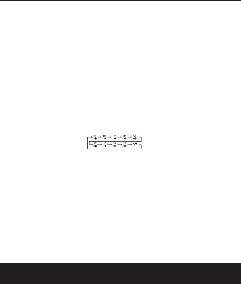
Sleep Button: Press this button to place the unit in the Sleep mode. After the time shown in the display, the DPR 2005 will automatically go into the Standby mode. Each press of the button changes the time until turn-off in the following order:
When the Sleep timer is in use, the front-panel displays and other indicators will dim to half-brightness.
Night Mode Button: Press this button to activate the Night mode. This mode is available in specially encoded Dolby Digital sources, and it preserves dialogue (center channel) intelligibility at low volume levels.
OSD Button: Press this button to activate or turn off the On-Screen Display (OSD) system used to set up or adjust the DPR 2005’s parameters.
Tone Control Button: This button controls the tone mode settings, enabling adjustment of the bass and treble boost/cut. You may also use it to take the tone controls out of the signal path completely for “flat” response. The first press of the button displays a
TONE IN message in the Lower Display Line
& and in the on-screen display. To take the controls out of the signal path press either of the ⁄/¤ Navigation Buttons o until the display reads TONE OUT. To change the bass or treble settings, press the button again until the desired option appears in the Lower Display Line & and on-screen display and then press either of the ⁄/¤ Navigation
Buttons o to enter the desired boost or cut setting. See page 30 for more information on the tone controls.
Mute Button: Press this button to momentarily silence the DPR 2005 or TV set being controlled, depending on which device has been selected.
AM/FM Button: Press this button to select the DPR 2005’s tuner as the listening choice. Pressing this button when the tuner is already in use will select between the AM and FM bands.
Channel Up/Down Selector: These selectors share the disc in the lower portion of the remote with the Volume Up/Down Buttons H. They have no function when the DPR is being controlled, but when programmed for use with a VCR, TV, cable box, satellite receiver or other similar product they will change the channel up or down. See pages 41 – 50 for more information on programming the remote.
Transport Play Buttons: These buttons have no direct function on the DPR 2005, but they are used when the remote is programmed for a compatible DVD, CD or tape player. Pressing these buttons will transmit a forwardor reverse-play command, according to the capabilities of the player being controlled. In the factory default setting, these buttons are programmed for Harman Kardon DVD players so that you may control a compatible player even when the remote is directly controlling the DPR, a TV set or a cable or satellite set-top box.
Delay Select Button: This button selects adjustments to the A/V Sync Delay and the individual channel delays. The first press of the button displays an A/V SYNC DELAY message in the Lower Display Line & and in the on-screen display, which means that you may change the amount of time that all channels are delayed together behind the video. This enables you to compensate for the loss of lip sync that may be caused by digital video processing in your display or by television stations. To change
the A/V Sync Delay, press the Set Button q while the A/V SYNC DELAY message is visible and then use the ⁄/¤ Navigation Button o to change the setting so that the sound and the video image are in sync. To change the delay for
an individual output channel, press the ⁄/¤ Navigation Button o until the desired channel name is shown, and then press the Set Button q. Use the ⁄/¤ Navigation Buttons o to change the delay amount. (See page 26 for more information on delay options.)
Speaker Select Button: Press this button
to begin the process of configuring the DPR 2005’s bass management system. Then press the ⁄/¤ Navigation Button o to select the channel you wish to set up. Press the Set Button q and
MAIN REMOTE CONTROL FUNCTIONS 13

MAIN REMOTE CONTROL FUNCTIONS
then select another channel to configure. When all adjustments have been completed, press the Set Button q twice to exit the settings and return to normal operation. (See page 24 for more information on speaker setup.)
Memory Button: Press this button to enter a radio station to the DPR 2005’s preset memory. First, tune the desired station, and then press this button. Within five seconds of when you see the station’s frequency flash in the Upper Display Line ^ and in the on-screen display, press the numeric keys
for the preset number between 01 and 30 that you wish to assign to the station. (See page 35 for more information.)
Stereo Mode Select Button: Press this button to select a stereo listening mode. When the button is pressed so that SURROUND OFF appears in the Lower Display Line &, the AVR will operate in a bypass mode with true, fully analog, two-channel left/right stereo mode with no surround processing or bass management, as opposed to other modes where digital processing is used. When the button is pressed
so that SURROUND OFF appears in the Lower Display Line &, and the DSP and SURROUND OFF Surround Mode Indicators * are lit, you will enjoy a two-channel presentation of the sound along with the benefits of bass management. Depending on whether your system is configured for 5.1 or 6.1/7.1 channels, the next press of the button will cause either
5 CH STEREO or 7 CH STEREO to appear, and the stereo signal will be routed to all five (or seven) speakers. (See page 32 for more information on stereo playback modes.)
DTS Neo:6 Mode Select Button: Press this button as needed to select one of the DTS Neo:6 modes. (See page 32 for the available DTS Neo:6 options.)
DTS Digital Mode Select Button: When a DTS-encoded digital source is playing, each press of this button will scroll through the available DTS modes. The specific choice of modes will vary according to the type of encoding on the disc and your system’s speaker configuration. When a DTS source is not in use, this button has no function. (See page 32 for the available DTS digital options.)
Dolby Mode Select Button: This button is used to select from the available Dolby Surround modes. Each press of this button will select one of the Dolby Pro Logic II or Dolby Pro Logic IIx modes. When a Dolby Digital-encoded source is in use, the Dolby Digital mode may also be selected. (See page 32 for the available Dolby surround mode options.)
8-Channel Input Select: Press this button to select the device connected to the 8-Channel Direct Inputs 40 . (See page 30 for more information.)
SPL Select Button: This button activates the EzSet function to quickly and accurately calibrate the DPR 2005’s output levels. When the button is pressed you will then need to select between automatic EzSet operation or using the remote as a manual SPL meter by pressing the ⁄/¤ Navigation Button o until your choice appears in the remote’s LCD display. Press the Set Button q to enter the setting, and then follow the instructions as displayed in the LCD display. (For complete information, see page 27.)
EzSet Microphone Sensor: The microphone sensor that is used by the EzSet system is behind the three slots at the top of the remote control. When using EzSet to calibrate the DPR 2005, be certain that the slots are not covered. (See page 27 for more information on using EzSet.)
Lens: The infrared emitters behind the plastic lens at the top of the remote communicate the remote codes to the DPR 2005. Be certain that the lens is not covered when using the remote, and point the lens toward the DPR for best results. In learning mode, the remote receives IR codes to be learned through a sensor behind the lens.
NOTE: DO NOT remove the rubber plug that is supplied to cover the jack on the upper right side of the remote. The jack is not active and is reserved for future use.
14 MAIN REMOTE CONTROL FUNCTIONS
ZONE II REMOTE CONTROL FUNCTIONS
|
POWER |
|
MUTE |
|
A |
OFF |
|
K |
|
|
AVR |
VID1 |
VID2 |
|
B |
|
|
|
|
|
AM/FM |
VID3 |
VID4 |
|
C |
|
|
|
|
D |
DVD |
CD |
TAPE |
|
|
|
|
||
E |
DN |
TUNING |
UP |
|
|
|
|
||
F |
DN |
PRESET |
UP |
|
G |
||||
|
|
|
H
DISC SKIP
J
DISC SKIP
I
VOLUME
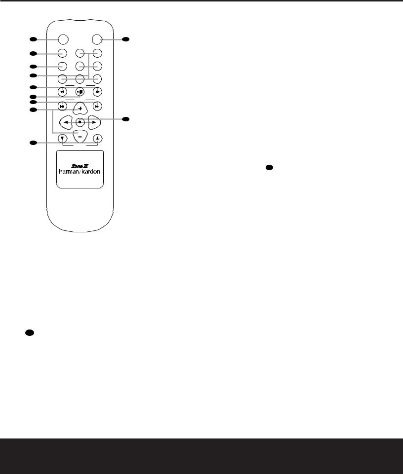
To make it easier to follow the instructions that refer to this illustration, a larger copy may be downloaded from the Product Support section for this product at www.harmankardon.com.
å Power Off Button
∫ AVR Selector Button
ç AM/FM Tuner Selector
∂ Input Selectors
≠ Tuning Up/Down – Fast Play Buttons
ƒ Record/Pause Button
© Preset Up/Down – Track Skip Buttons
˙ Disc Skip Buttons
I Volume Up/Down Buttons
∆ Play Forward/Reverse/Stop Buttons
˚ Mute Button
The Zone II remote may be used either in the same room where the DPR 2005 is located or in a separate room with an optional infrared sensor that is connected to the DPR 2005’s Multiroom IR Input jack. When it is used in the same room as the DPR 2005, it will control the functions of the DPR 2005 or any compatible Harman Kardon products in that room. When it is used in a separate room via a sensor connected to the Multiroom IR Input jack, the buttons for Power, Input Source, Volume and Mute will control the source and volume for the second zone, as connected to the Multiroom Audio Outputs ª jacks. (See page 39 for complete information on using the Multiroom system.)
å Power Off Button: When used in the room where the DPR 2005 is located, press this button to place the unit in Standby. When it is used in a remote room with a sensor that is connected to the Multiroom IR Input jack, this button turns the Multiroom system on and off.
∫ AVR Selector Button: Press this button to turn on the DPR 2005. The input in use when the unit was last on will be selected.
ç AM/FM Tuner Selector: Press this button to select the Tuner as the input to the Multiroom system. Press it again to change between the AM and FM bands.
∂ Input Selectors: When the DPR 2005 is off, press one of these buttons to select a specific input and turn the unit on. When the unit is already in use, pressing one of these buttons will change the input.
NOTE: The Zone II remote may not be used to select the Front-Panel Video 5 Input K. However, you may assign a source connected to these jacks to the Multiroom System using the Multiroom Button ` on the remote or the MULTI-ROOM SETUP menu. See page 39 for more information.
≠ Tuning Up/Down – Fast Play Buttons: When the Zone II remote is used in the same room as the DPR 2005, these buttons may be used to change the
frequency of the tuner. These buttons may also control the Fast Play or Fast Reverse functions of compatible Harman Kardon CD, DVD or cassette decks in the same room, or from a remote room when an IR link is connected to the DPR 2005.
ƒ Record/Pause Button: Press this button to activate the Record or Pause function on compatible Harman Kardon CD, DVD or cassette deck products.
© Preset Up/Down – Track Skip Buttons: When the DPR 2005’s tuner is selected as the input source, these buttons will move up or down through the list of stations that have been stored in the preset memory.
When a CD or DVD changer or player is selected, these buttons activate the Forward or Reverse Track or Chapter Skip functions.
˙ Disc Skip Buttons: Press these buttons to change discs on a compatible Harman Kardon CD or DVD changer or player.
I Volume Up/Down Buttons: When the Zone II remote is used in the room where the DPR 2005 is located, press this button to raise or lower the volume in that room. When it is used in a remote room with a sensor that is connected to the Multiroom IR Input f jack, this button will raise or lower the volume in the remote room.
∆ Play Forward/Reverse/Stop Buttons: Press these buttons to control compatible Harman Kardon CD, DVD or cassette players.
˚ Mute Button: When the Zone II remote is used in the room where the DPR 2005 is located, press this button to temporarily silence the unit. When it is used in a remote room with a sensor that is connected to the Multiroom IR Input jack, this button will temporarily silence the feed to the remote room
only. Press the button again to return to the previous volume level.
ZONE II REMOTE CONTROL FUNCTIONS 15
INSTALLATION AND CONNECTIONS
System Installation
After unpacking the unit, locating it in a place with adequate ventilation and placing it on a solid surface capable of supporting its weight, you will need to make the connections to your audio and video equipment.
IMPORTANT NOTE: For your personal safety and to avoid possible damage to your equipment and speakers, it is always good practice to turn off and unplug the DPR and ALL source equipment from the AC output before making any audio or video system connections.
Audio Equipment Connections
We recommend that you use high-quality interconnect cables when making connections to source equipment and recorders to preserve the integrity of the signals.
1.Connect the analog output of a CD player to the
CD Inputs ‚.
NOTE: If your CD player has both fixed and variable audio outputs, it is best to use the fixed output unless you find that the input to the receiver is so low that the sound is noisy, or so high that it is distorted.
2.Connect the analog Play/Out jacks of a cassette deck, MD, CD-R or other audio recorder to the Tape Inputs ¤. Connect the analog Record/In jacks on the recorder to the Tape Outputs ⁄ on the DPR 2005.
3.Connect the output of any digital audio source such as such as a CD or DVD changer or player, advanced video game, a digital satellite receiver, HDTV tuner or digital cable set-top box or the output of a compatible computer sound card to the Optical and Coaxial Digital Audio Inputs
fl‡HJ.
4.Connect the coaxial or optical Digital Audio Outputs °· on the rear panel of the DPR 2005 to the matching digital input connections on a CD-R or MiniDisc recorder.
5.Assemble the AM loop antenna supplied with the unit so that the tabs at the bottom of the antenna loop snap into the holes in the base. Connect it to the
AM and GND Screw Terminals 36 .
6.Connect the supplied FM antenna to the FM (75Ohm) Connection 35 . The FM antenna may be an external roof antenna, an inside powered or wire-lead antenna or a connection from a cable TV system. If the antenna or connection uses 300-
ohm twin-lead cable, you must use an optional 300-ohm-to-75-ohm adapter to make the connection.
7.Connect the front, center, surround and surround back speaker outputs efgh to the respective speakers.
To ensure that all the audio signals are carried to your speakers without loss of clarity or resolution, we suggest that you use high-quality speaker cable. Many brands of cable are available and the choice of cable may be influenced by the distance between your speakers and the receiver, the type of speakers you use, personal preferences and other factors. Your dealer or installer is a valuable resource to consult in selecting the proper cable.
Regardless of the brand of cable selected, we recommend that you use cable with a gauge of 14 or smaller. Remember that in specifying cable, the lower the number, the thicker the cable.
Cable with a gauge of 16 may be used for short runs of less than ten feet. We do not recommend that you use cables with an AWG equivalent of 18 or higher, due to the power loss and degradation in performance that will occur.
Cables that are run inside walls should have the appropriate markings to indicate listing with UL, CSA or other appropriate testing agency standards. Questions about running cables inside walls should be referred to your installer or a licensed electrician who is familiar with the NEC and/or the applicable building codes in
your area.
When connecting wires to the speakers, be certain to observe proper polarity. Note that the positive (+) terminal of each speaker connection now carries a specific color code, as noted on page 8. However, most speakers still use a red terminal for the positive connection. Connect the “negative” or “black” wire to the same terminal on both the receiver and the speaker.
NOTE: While most speaker manufacturers adhere to an industry convention of using black terminals for negative and red ones for positive, some may vary from this configuration. To ensure proper phase and optimal performance, consult the identification plate on your speaker or the speaker’s manual to verify polarity. If you do not know the polarity of your speaker, ask your dealer for advice before proceeding, or consult the speaker’s manufacturer.
We also recommend that the length of cable used to connect speaker pairs be identical. For example, use the same length piece of cable to connect the front-left and front-right or surround-left and sur-
round-right speakers, even if the speakers are a different distance from the DPR 2005.
8.Connections to a subwoofer are normally made via a line-level audio connection from the Subwoofer Output › to the line-level input of a subwoofer with a built-in amplifier. When a passive subwoofer is used, the connection first goes to a power amplifier, which will be connected to one or more subwoofer speakers. If you are using a powered subwoofer that does not have line-level input connections, follow the instructions furnished with the speaker for connection information.
9.If an external multichannel audio source with 5.1 outputs such as an external digital processor/ decoder, DVD-Audio or SACD player is used, connect the outputs of that device to the
8-Channel Direct Inputs fi.
Video Equipment Connections
Video equipment is connected in the same manner as audio components. Again, the use of high-quality interconnect cables is recommended to preserve signal quality.
1.Connect the composite video or S-Video Play/ Out jack of a VCR, Personal Video Receiver (PVR)
or DVD-Recorder to the Video 1 or Video 2 Video Input Jacks ¢§ on the rear panel. Although any other video device may also be connected to these jacks, we particularly recommend that VCRs and PVRs be connected to the Video 1 Input Jacks so that you are able to take advantage of the remote control codes for these devices that are programmed for the “Video1/VCR” button of the unit’s remote control.
2.Connect the composite video or S-Video Record/In jacks of a VCR, Personal Video Recorder (PVR) or DVD-Recorder to the Video 1 or Video 2 Video Output Jacks £∞ on the rear panel. Although any other video device may also be connected to these jacks, we particularly recommend that VCRs and PVRs be connected to the Video 1 Output Jacks so that you are able to take advantage of the remote control codes for these devices that are programmed for the “Video 1/VCR” button of the unit’s remote control.
3.Connect the composite video or S-Video Play/Out jacks of any video playback device to the Video 3 or Video 4 Video Input Jacks ¡™ on the rear panel. Although any type of video source device may be connected to these jacks, the remote control has the commands for the Video 3 inputs set to control a cable set-top box and the commands for the Video 4 inputs set to control a satellite receiver. However, you may reassign the commands for any type of device to either button on the remote using
16 INSTALLATION AND CONNECTIONS
 Loading...