


AVR 1550 Audio/Video Receiver |
OWNER’S MANUAL |
® |
Power for the Digital Revolution™ |
Table of Contents
3Introduction
4Safety Information
4Unpacking
5Front Panel Controls
7Front Panel Information Display
8Rear Panel Connections
9Remote Control Functions
11 Installation and Connections
11Audio Equipment Connections
11Video Equipment Connections
12SCART A/V Connections
13Speaker Selection and Placement
14System Configuration
14 First Turn On
14Settings to be Made With Each Input Used
14 Input Setup
14 Speaker Setup
14 Surround Setup
16Making Settings independent of selected Input
16Delay Settings
17Night Mode Settings
17 |
Output Level Adjustment |
19 |
Operation |
19Basic Operation
19Source Selection
19Controls and Use of Headphones
20Surround Mode Chart
21Surround Mode Selection
21Digital Audio Playback
22Selecting a Digital Source
22Digital Status Indicators
22Night Mode
23Tape Recording
23Output Level Trim Adjustment
23Display Brigthness
23Memory Backup
24Tuner Operation
24 RDS Operation
26Function List
27Troubleshooting Guide
27Processor Reset
28Technical Specifications
Declaration of Conformity
We, Harman Consumer International
2, route de Tours
72500 Château-du-Loir,
FRANCE
declare in own responsibility, that the product described in this owner’s manual is in compliance with technical standards:
EN 55013/6.1990
EN 55020/12.1994
EN 60065:1993
EN 61000-3-2/4.1995
Carsten Olesen
Harman Kardon Europe A/S
09/02
Typographical Conventions
In order to help you use this manual with the remote control, front-panel controls and rear-panel connections, certain conventions have been used.
EXAMPLE – (bold type) indicates a specific remote control or front-panel button, or rear-panel connection jack
EXAMPLE – (OCR type) indicates a message that is visible on the front-panel information display
1– (number in a square) indicates a specific front-panel control
– (number in a circle) indicates a rear-panel connection
0– (number in an oval) indicates a button or indicator on the remote
A– (letter in a square) indicates an indicator in the front-panel display
2 TABLE OF CONTENTS

Introduction
Thank you for choosing Harman Kardon!
With the purchase of a Harman Kardon
AVR 1550 you are about to begin many years of listening enjoyment. The AVR 1550 has been custom designed to provide all the excitement and detail of movie sound tracks and every nuance of musical selections. With onboard Dolby* Digital and DTS† decoding, the AVR 1550 delivers six discrete channels of audio that take advantage of the digital sound tracks from the latest DVD and LD releases and Digital Television broadcasts.
To obtain the maximum enjoyment from your new receiver, we urge you to take the time to read through this manual. This will ensure that connections to speakers, source playback units and other external devices are made properly. In addition, a few minutes spent learning the functions of the various controls will enable you to take advantage of all the power the AVR 1550 is able to deliver.
If you have any questions about this product, its installation or its operation, please contact your dealer. He is your best local source of information.
Description and Features
The AVR 1550 is among the most versatile and multi-featured A/V receivers available, incorporating a wide range of listening options. In addition to Dolby Digital and DTS decoding for digital sources, a broad choice of analog surround modes are available for use with sources such as CD, VCR, TV broadcasts and the AVR’s own FM/AM tuner.
In addition to providing a wide range of listening options, the AVR 1550 is easy to configure so that it provides the best results with your speakers and specific listening-room environment.
For the ultimate in flexibility, the AVR 1550 features connections for three video devices, partially with both composite and S-Video inputs.
Two additional audio inputs are available, and a total of two digital inputs make the AVR 1550 capable of handling all the latest digital audio sources. A coax digital output is available for direct connection to digital recorders.
The AVR 1550’s powerful amplifier uses traditional Harman Kardon high-current design technologies to meet the wide dynamic range of any program selection.
Harman Kardon invented the high-fidelity receiver more than forty-seven years ago. With state- of-the-art circuitry and time-honored circuit designs, the AVR 1550 is one of the finest receivers ever offered by Harman Kardon within its price range.
■Onboard Dolby Digital and DTS Decoding Using Crystal® Chip Technology
■Dolby Laboratory's latest ProLogic II decoding technology
■Multiple Digital Inputs and Outputs
■Front-Panel Inputs for Easy Connection to Portable Devices and the Latest Video Game Consoles
INTRODUCTION 3

Safety Information
Important Safety Information
Verify Line Voltage Before Use
Your AVR 1550 has been designed for use with 220-240-Volt AC current. Connection to a line voltage other than that for which it is intended can create a safety and fire hazard and may damage the unit.
If you have any questions about the voltage requirements for your specific model, or about the line voltage in your area, contact your dealer before plugging the unit into a wall outlet.
Do Not Use Extension Cords
To avoid safety hazards, use only the power cord attached to your unit. We do not recommend that extension cords be used with this product. As with all electrical devices, do not run power cords under rugs or carpets or place heavy objects on them. Damaged power cords should be replaced immediately by an authorized service depot with a cord meeting factory specifications.
Handle the AC Power Cord Gently
When disconnecting the power cord from an AC outlet, always pull the plug, never pull the cord. If you do not intend to use the unit for any considerable length of time, disconnect the plug from the AC outlet.
Do Not Open the Cabinet
There are no user-serviceable components inside this product. Opening the cabinet may present a shock hazard, and any modification to the product will void your guarantee. If water or any metal object such as a paper clip, wire or a staple accidentally falls inside the unit, disconnect it from the AC power source immediately, and consult an authorized service station.
Installation Location
■To assure proper operation and to avoid the potential for safety hazards, place the unit on a firm and level surface. When placing the unit on a shelf, be certain that the shelf and any mounting hardware can support the weight of the product.
■Make certain that proper space is provided both above and below the unit for ventilation. If this product will be installed in a cabinet or other enclosed area, make certain that there is sufficient air movement within the cabinet. Under some circumstances a fan may be required.
■Do not place the unit directly on a carpeted surface.
■Avoid installation in extremely hot or cold locations, or an area that is exposed to direct sunlight or heating equipment.
■Avoid moist or humid locations.
■Do not obstruct the ventilation slots on the top of the unit, or place objects directly over them.
Cleaning
When the unit gets dirty, wipe it with a clean, soft, dry cloth. If necessary, wipe it with a soft cloth dampened with mild soapy water, then a fresh cloth with clean water. Wipe dry immediately with a dry cloth. NEVER use benzene, aerosol cleaners, thinner, alcohol or any other volatile cleaning agent. Do not use abrasive cleaners, as they may damage the finish of metal parts. Avoid spraying insecticide near the unit.
Moving the Unit
Before moving the unit, be certain to disconnect any interconnection cords with other components, and make certain that you disconnect the unit from the AC outlet.
Unpacking
The carton and shipping materials used to protect your new receiver during shipment were specially designed to cushion it from shock and vibration. We suggest that you save the carton and packing materials for use in shipping if you move, or should the unit ever need repair.
To minimize the size of the carton in storage, you may wish to flatten it. This is done by carefully slitting the tape seams on the bottom and collapsing the carton. Other cardboard inserts may be stored in the same manner. Packing materials that cannot be collapsed should be saved along with the carton in a plastic bag.
If you do not wish to save the packaging materials, please note that the carton and other sections of the shipping protection are recyclable. Please respect the environment and discard those materials at a local recycling center.
4 SAFETY INFORMATION
Front Panel Controls
^$# * Ô Ó &
(
1
2
3 4 5 6 7 8 9 ) ! @ |
% |
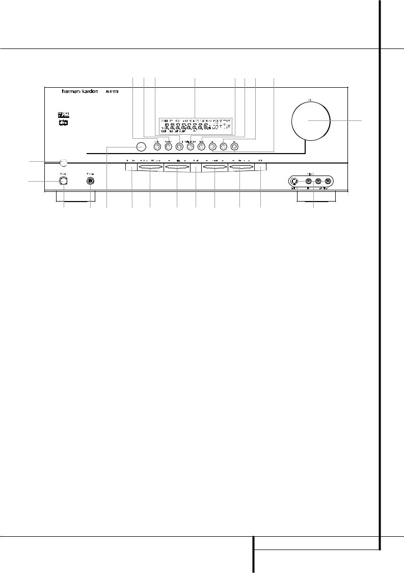
1 Main Power Switch
2 System Power Control
3 Power Indicator
4 Headphone Jack
5 Remote Sensor Window
6 Tone Mode
7 Surround Mode Selector
8 Tuning
1Main Power Switch: Press this button to apply power to the AVR 1550. When the switch is pressed in, the unit is placed in a Standby mode, as indicated by the orange LED 3surrounding the System Power Control 2. This button MUST be pressed in to operate the unit. To turn the unit off completely and prevent the use of the remote control, this switch should be pressed until it pops out from the front panel so that the word “OFF” may be read at the top of the switch.
NOTE: This switch is normally left in the “ON” position.
9 Tuner Band Selector )Preset Stations Selector !Input Source Selector @RDS Select Button
#Channel Select Button $Speaker Select Button %Video 3 input jacks ^Test Tone Selector
2System Power Control: When the Main Power Switch 1is “ON,” press this button to turn on the AVR 1550; press it again to turn the unit off (to Standby). Note that the Power Indicator surrounding the switch 3will turn green when the unit is on.
3Power Indicator: This LED will be illuminated in orange when the unit is in the Standby mode to signal that the unit is ready to be turned on. When the unit is in operation, the indicator will turn green.
4Headphone Jack: This jack may be used to listen to the AVR 1550’s output through a pair of headphones. Be certain that the headphones have a standard 6.3 mm stereo phone plug. Note that the speakers will automatically be turned off when the headphones are connected.
&Selector Buttons
*Main Information Display
(Volume Control
ÓSet Button
ÔDigital Input Selector
Delay
5 Remote Sensor Window: The sensor behind this window receives infrared signals from the remote control. Aim the remote at this area and do not block or cover it unless an external remote sensor is installed.
6Tone Mode: Pressing this button activates the menu for setting the Bass and Treble controls.
FRONT PANEL CONTROLS 5

Front Panel Controls
7Surround Mode Selector: Press this button to change the surround mode by scrolling through the list of available modes. Note that Dolby Digital and DTS modes can be selected only when a digital input is used (See page 20 for more information about surround modes.)
8Tuning Selector: Press the left side of the button to tune lower frequency stations and the right side of the button to tune higher frequency stations. When a station with a strong signal is reached, the TUNED indicator Lwill illuminate in the Main Information Display *
(see page 24 for more information on tuning stations).
9Tuner Band Selector: Pressing this button will automatically switch the AVR to the Tuner mode. Pressing it again will switch between the AM and FM frequency bands, holding it pressed for some seconds will switch between stereo and mono receiving and between automatic and manual tuning mode (See page 24 for more information on the tuner).
)Preset Stations Selector: Press this button to scroll up or down through the list of stations that have been entered into the preset memory. (See page 24 for more information on tuner programming.)
!Input Source Selector: Press this button to change the input by scrolling through the list of input sources.
@RDS Select Button: Press this button to display the various messages that are part of the RDS data system of the AVR 1550’s tuner. (See page 24 for more information on RDS).
#Channel Select Button: Press this button to begin the process of trimming the channel output levels using an external audio source. (For more information on output level trim adjustment, see page 23.)
$Speaker Select Button: Press this button to begin the process of selecting the speaker positions that are used in your listening room. (See page 14 for more information on setup and configuration.)
%Video 3 Input Jacks: These audio/video jacks may be used for temporary connection to video games or portable audio/video products such as camcorders and portable audio players.
^Test Tone Selector: Press this button to begin the process of adjusting the channel output levels using the internal test tone as a reference. (For more information on output level adjustment, see page 17.)
&Selector Buttons: When you are establishing the AVR 1550’s configuration settings, use these buttons to select from the choices available, as shown in the Main Information Display *.
* Main Information Display: This display delivers messages and status indications to help you operate the receiver. (See pages 7–8 for a complete explanation of the Information Display.)
(Volume Control: Turn this knob clockwise to increase the volume, counterclockwise to decrease the volume. If the AVR is muted, adjusting volume control will automatically release the unit from the silenced condition.
ÓSet Button: When making choices during the setup and configuration process, press this button to enter the desired setting as shown in the Main Information Display *into the AVR 1550’s memory. The set button may also be used to change the display brightness.
(See page 23.)
ÔDigital Input Selector: When playing a source that has a digital output, press this button to select between the Optical and Coaxial Digital inputs. (See pages 21-22 for more information on digital audio.)
Delay: Press this button to begin the sequence of steps required to enter delay time settings. (See page 16 for more information on delay times.)
6 FRONT PANEL CONTROLS
Front Panel Information Display
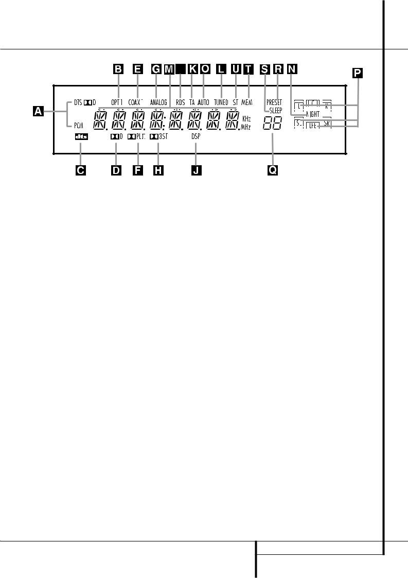
ABitstream Indicators
B Optical Source Indicators C DTS Mode Indicator
D Dolby Digital Indicator
E Coaxial Digital Input Indicators F Dolby Pro Logic II Indicator G Analog Input Indicator
ABitstream™ Indicators: When the input is a digital source, one of these indicators will light to display the specific type of signal in use.
BOptical Source Indicators: These indicators light to show when a Optical Digital Input has been selected.
CDTS Mode Indicator: This indicator illuminates when the DTS mode is selected.
DDolby Digital Indicator: This indicator illuminates when Dolby Digital mode is selected.
ECoaxial Digital Input Indicators: These indicators light to show when a Coaxial Digital Input has been selected.
FDolby Pro Logic II Indicator: This indicator lights when the Dolby Pro Logic II mode has been selected.
GAnalog Input Indicator: This indicator lights when an analog input source has been selected.
HDolby 3 Stereo Indicator: This indicator lights when the Dolby 3 Stereo Mode has been selected. Only ST (Stereo) will light when "Surround Off" has been selected. Then all Surround Modes are turned off and the unit will play in pure stereo mode.
IRDS Indicator: This indicator illuminates when the station tuned is transmitting RDS data.
H Dolby 3 Stereo Indicator
I RDS Indicator
JDSP Mode Indicator
K Traffic Program Indicator L Tuned Indicator
M Main Information Display N Night Mode Indicator
JDSP Mode Indicator: This indicator lights when any of the surround modes created by Digital Signal Processing, or DSP are in use. These modes include Hall 1, Hall 2, Theater and 5 Channel Stereo.
KTraffic Program Indicator: This indicator illuminates if the RDS station tuned sometimes transmits traffic information (see page 24 for more information on RDS).
LTuned Indicator: This indicator illuminates when a station is being received with sufficient signal strength to provide acceptable listening quality.
MMain Information Display: This display shows messages relating to the status, input source, surround mode, tuner, volume level or other aspects of unit’s operation.
NNight Mode Indicator: This indicator lights when the AVR 1550 is in the Night mode, which preserves the dynamic range of digital program material at low volume levels.
OAuto Indicator: This indicator illuminates when the tuner’s Auto mode is in use.
PSpeaker/Channel Input Indicators: These indicators are multipurpose, indicating either the speaker type selected for each channel or the incoming data-signal configuration. The left, center, right, right surround and left surround speaker indicators are composed of three boxes, while the subwoofer is a single box. When the letters flash, the digital input has been interrupted. (See page 18 and 27 for more information on the Channel Indicators).
O Auto Indicator
P Speaker/Channel Input Indicators
QPreset Number/Sleep Timer R Preset Indicator
S Sleep Indicator T Memory Indicator U Stereo Indicator
QPreset Number/Sleep Timer: When the tuner is in use, these numbers indicate the specific preset memory location in use. (See page 24 for more information on preset stations.) When the Sleep function is in use, these numbers show how many minutes remain before the unit goes into the Standby mode.
RPreset Indicator: This indicator lights when the tuner is in use to show that the Preset Number/Sleep Timer Qis showing the station’s preset memory number. (See page 24 for more information on tuner presets.)
SSleep Indicator: This indicator lights when the Sleep function is in use. The numbers in the Preset/Sleep Number Indicators will show the minutes remaining before the AVR 1550 goes into the Standby mode. (See page 19 for more information on the Sleep function.)
TMemory Indicator: This indicator flashes when entering presets and other information into the tuner’s memory.
UStereo Indicator: This indicator illuminates when an FM station is being tuned in stereo.
FRONT PANEL INFORMATION DISPLAY 7

Rear Panel Connections
ª |
|
a |
|
¶ |
¢ |
|
¤ |
‡ |
‚ |
¡ |
• |
£ |
|
· b |
|
|
|
fl |
⁄ |
™ |
° |
∞ § |
fi |
› |
‹ |
|
Tape InputsTape Outputs
Video 1 Audio InputsAM Antenna
Video 1 Audio Outputs Video 2 Audio Inputs
FM Antenna
Tape Inputs: Connect these jacks to the PLAY/OUT jacks of an audio recorder.
Tape Outputs: Connect these jacks to the RECORD/INPUT jacks of an audio recorder.
Video 1 Audio Inputs: Connect these jacks to the PLAY/OUT audio jacks on a VCR or other video source.
AM Antenna: Connect the AM loop antenna supplied with the receiver to these terminals. If an external AM antenna is used, make connections to the AM and GND terminals in accordance with the instructions supplied with the antenna.
Video 1 Audio Outputs: Connect these jacks to the RECORD/INPUT audio jacks on a VCR or any other Audio recorder.
Video 2 Audio Inputs: Connect these jacks to the PLAY/OUT audio jacks on a VCR or other video source.
FM Antenna: Connect the supplied indoor or an optional external FM antenna to this terminal.
CD Inputs: Connect these jacks to the analog output of a compact disc player or CD changer.
CoaxialDigital Audio Outputs: Connect this jack to the matching digital input connector on a digital recorder such as a CD-R or MiniDisc recorder.
CD Inputs
Coaxial Digital Audio Outputs
Coaxial Digital Inputs
Subwoofer Output
Video Monitor Outputs
Front/Center Speaker OutputsSurround Speaker Outputs
Coaxial Digital Inputs: Connect the coax digital output from a DVD player. Do not connect the RF digital output of an LD player to these jacks.
Subwoofer Output: Connect this jack to the line-level input of a powered subwoofer. If an external subwoofer amplifier is used, connect this jack to the subwoofer amplifier input.
Video Monitor Outputs: Connect these jacks to the composite and/or S-Video input of a TV monitor or video projector to view the output of any video source selected by the receiver’s video switcher.
Front/Center Speaker Outputs: Connect these outputs to the matching + or – terminals on your front/center speakers. When making speaker connections, always make certain to maintain correct polarity by connecting the red
(+) terminals on the AVR 1550 to the red (+) terminals on the speaker and the black (–) terminals on the AVR 1550 to the black (–) terminals on the speakers. (See page 11 for more information on speaker polarity.)
Surround Speaker Outputs: Connect these outputs to the matching + or – terminals on your left and right surround speakers. When making speaker connections always make certain to maintain correct polarity by connecting
TV Audio Inputs
Optical Digital Inputs
AC Power Cord
DVD Video Inputs
Video 1 Video Outputs
Video 1 Video Inputs
Video 2 Video Inputs
the red (+) terminals on the AVR 1550 to the red (+) terminals on the speakers and the black
(–) terminals on the AVR 1550 to the black (–) terminals on the speakers. See page 11 for more information on speaker polarity.
TV Audio Inputs: Connect these jacks to the Audio Out jacks on a TV or other video source.
Optical Digital Inputs: Connect the optical digital output from a DVD player, HDTV receiver, LD player, MD player or CD player to these jacks. The signal may be either a Dolby Digital signal, a DTS signal or a standard PCM digital source.
AC Power Cord: Connect the AC plug to an unswitched AC wall output.
DVD Video Inputs: Connect these jacks to the composite or S-Video output jacks on a DVD player or other video source.
Video 1 Video Outputs: Connect these jacks to the RECORD/INPUT composite or S-Video jack on a VCR.
Video 1 Video Inputs: Connect these jacks to the PLAY/OUT composite or S-Video jacks on a VCR or other video source.
Video 2 Video Inputs: Connect these jacks to the PLAY/OUT composite jacks on a second VCR or other video source.
8 REAR PANEL CONNECTIONS
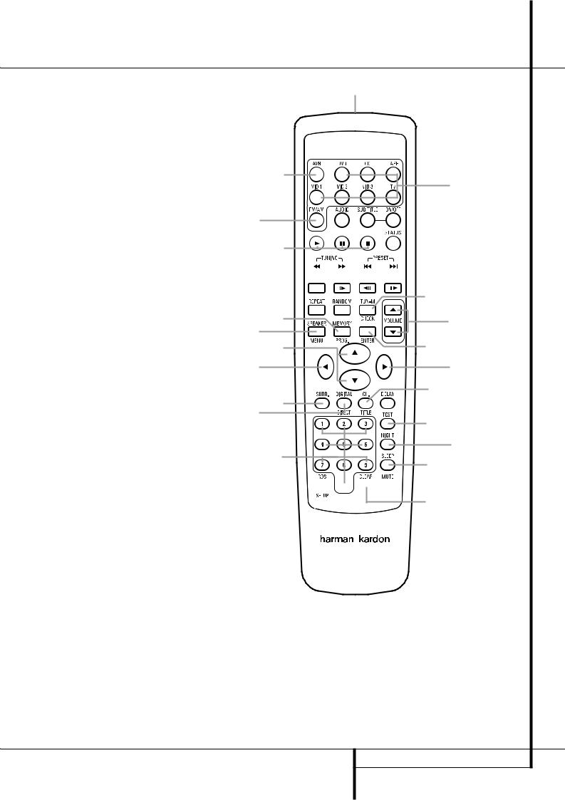
Remote Control Functions
0Power On Button
1IR Transmitter Window
2Mute
3Power Off Button
4Input Selectors
5AVR Selector
6AM/FM Tuner Select
7Test Button
8Sleep Button
9Surround Mode Selector
ANight Mode
BChannel Select Button
C⁄/ ¤ Buttons
D‹ Button
EEnter Button
FDigital Select/Direct Button
GNumeric Keys
HTuner Mode
IVolume Up/Down
JTuning Up/Down
KSpeaker Select
LTransport Controls
M› Button
NRDS Select Button
OPreset Up/Down
PClear Button
QMemory Button
Delay
NOTE: The function names shown here are each button’s feature when used with the AVR. Most buttons have additional functions when used with other Harman Kardon devices.
See page 26 for a list of these functions.
b
a


 d
d
f
e
g
v
t

 y
y
|
r |
` |
s |
u |
|
m |
o |
n |
w |
|
l |
j
p
7
k
q
8
x


 c z
c z
IMPORTANT NOTE: The AVR 1550’s remote is shipped from the factory to operate the
AVR 1550 and most Harman Kardon CD or DVD players and cassette decks.
Before using the remote, it is important to remember to press the Input Selector button 4that corresponds to the unit you wish to operate.
It is also important to remember that many of the buttons on the remote take on different functions, depending on the product selected using the Input Selectors. The descriptions shown here primarily detail the functions of the remote when it is used to operate the
AVR 1550. (See page 26 for information about alternate functions for the remote’s buttons.)
AVR 1550
0Power On Button: Press this button to turn on the power.
1IR Transmitter Window: Point this window towards the AVR 1550 when pressing buttons on the remote to make certain that infrared commands are properly received.
2Mute: Press this button to momentarily silence the AVR 1550 or TV set being controlled, depending on which device has been selected.
3Power Off Button: Press this button to place the AVR 1550 in the Standby mode.
4Input Selectors: Pressing one of these buttons will perform three actions at the same time. First, if the AVR is not turned on, this will power up the unit. Next, it will select the source shown on the button as the input to the AVR. Finally, it will change the remote control so that it controls the compatible Harman Kardon product selected. After pressing one of these buttons you must press the AVR Selector button 5
REMOTE CONTROL FUNCTIONS 9
 Loading...