


AVR 5550 Audio/Video Receiver |
OWNER’S MANUAL |
AVR 5550 |
LOGIC 7 |
VMAx |
ready |
® |
Power for the Digital Revolution™ |
Table of Contents
3Introduction
4Safety Information
4Unpacking
5Front Panel Controls
7Front Panel Information Display
8Rear Panel Connections
11 Main Remote Control Functions
14Zone II Remote Control Functions
15Installation and Connections
15Audio Connections
15Video Connections
16SCART A/V Connections
18System and Power Connections
19Speaker Selection
19Speaker Placement
20System Configuration
20First Turn On
20Using the On-Screen Display
20System Setup
21Input Setup
21 Speaker Setup
24Surround Setup
25Adjustments for Other Inputs
25Delay Settings
25Night Mode Settings
26Output Level Adjustment
26Using EzSet
27Manual Output Level Adjustment
29Operation
29Surround Mode Chart
31Basic Operation
31Source Selection
316/8-Channel Direct Input
32Controls and Use of Headphones
32Surround Mode Selection
33Digital Audio Playback
33Dolby Digital
33 |
DTS |
33 |
PCM Audio Playback |
33 |
HDCD |
33MP3 Audio Playback
34Selecting a Digital Source
34Digital Bitstream Indicators
34Speaker/Channel Indicators
35Night Mode
35 Tape Recording
35Front Panel Input/Output Connections
36Output Level Adjustment
With Source Signals
36Memory backup
37Advanced Features
37Surround Amplifier Channel Assignment
37Display Brightness
37Turn-On Volume Level
38Semi-OSD Settings
38 |
Full-OSD Time Out Adjustment |
38 |
Multiroom Operation |
40 |
Tuner Operation |
40 |
Basic Tuner Operation |
40 |
Station Selection |
40 |
Preset Tuning |
40 |
RDS Operation |
40 |
RDS Tuning |
40RDS Display Options
41Program Search
42Programming the Remote
42Programming the Remote with Codes
42Direct Code Entry
42Auto Search Method
43Code Readout
43 Learning Codes
43 |
Erasing Learned Codes |
50 |
Troubleshooting Guide |
44 |
Macro Programming |
50 |
Processor Reset |
45 |
Programmed Device Functions |
51 |
Technical Specifications |
45Volume Punch-Through
46Channel Control Punch-Through
46Transport Control Punch-Through
46Reassigning Device Control Selectors
47Resetting the Remote Memory
48Function List
Declaration of Conformity
We, Harman Consumer International
2, route de Tours
72500 Château-du-Loir,
FRANCE
declare in own responsibility, that the product described in this owner’s manual is in compliance with technical standards:
EN 55013/6.1990
EN 55020/12.1994
EN 60065:1993
EN 61000-3-2/4.1995
Carsten Olesen
Harman Kardon Europe A/S
11/02
Typographical Conventions
In order to help you use this manual with the remote control, front-panel controls and rear-panel connections, certain conventions have been used.
EXAMPLE – (bold type) indicates a specific remote control or front-panel button, or rear-panel connection jack
EXAMPLE – (OCR type) indicates a message that is visible on the front-panel information display
1– (number in a square) indicates a specific front-panel control
– (number in a circle) indicates a rear-panel connection
0– (number in an oval) indicates a button or indicator on the remote
A– (letter in a square) indicates an indicator in the front-panel display
å– (letter in an oval) indicates a button on the Zone II remote
2 TABLE OF CONTENTS

Introduction
Thank you for choosing Harman Kardon!
With the purchase of a Harman Kardon
AVR 5550 you are about to begin many years of listening enjoyment. Designed to provide all the excitement and detail of movie soundtracks and every nuance of musical selections, the
AVR 5550 is truly a multichannel receiver for the new millennium. In addition to the traditional 5.1 digital decoding modes such as Dolby Digital and DTS, it offers the latest advancements in surround technology such as Dolby Pro Logic II, the full suite of DTS-ES 6.1 modes, DTS Neo:6 and the latest 7.1 channel versions of Harman's own Logic 7 technology.
The AVR 5550 has been engineered so that it is easy to take advantage of all the power of its digital technology. On-screen menus, fully color coded connection jacks and terminals and our exclusive EzSet™ remote make installation fast and simple. However, to obtain the maximum enjoyment from your new receiver, we urge you to read this manual. A few minutes spent learning the functions of the various controls will enable you to take advantage of all the power the AVR 5550 is able to deliver.
If you have any questions about this product, its installation or its operation, please contact your retailer or custom installer. They are your best local sources of information.
Description and Features
The AVR 5550 is among the most versatile and multifeatured A/V receivers available, incorporating a wide range of listening options. In addition to Dolby Digital and DTS decoding for digital sources, a broad choice of surround modes for Matrix surround-encoded or Stereo recordings are available for use with sources such as CD, VCR, TV broadcasts and the AVR 5550’s own FM/AM tuner. Along with Dolby Digital EX, Dolby Pro Logic II, DTS Neo:6, Dolby 3 Stereo,
5 Channel or 7 Channel Stereo and Hall and Theater modes, the AVR 5550 offers Harman International’s exclusive Logic 7 process in both 5.1 and 7.1 versions to create a wider, more enveloping field environment and more defined fly-overs and pans. Another Harman Kardon exclusive is VMAx, which uses proprietary processing to create an open, spacious sound field even when only two front speakers are available. Finally, the AVR 5550 is among the very few A/V receivers that offer decoding of MP3 data, so that you may listen to the latest music selections directly from compatible computers or playback devices with the power and fidelity you expect from Harman Kardon.
The AVR 5550 is also featuring HDCD® decoding to provide the most realistic playback of CDs when a digital connection is used, even with a normal non-HDCD-compatible CD or DVD player.
In addition to providing a wide range of listening options, the AVR 5550 is easy to configure so that it provides the best results with your speakers and specific listening-room environment. Onscreen menus make it simple to enter settings for speaker configurations and bass management, and the EzSet remote measures a system’s sound levels and automatically calibrates them for perfectly balanced sound field presentation.
For the ultimate in flexibility, the AVR 5550 features connections for five video devices, all with both composite and S-Video inputs. Two additional audio inputs are available, and a total of six digital inputs and three outputs make the AVR 5550 capable of handling all the latest digital audio sources.
For compatibility with the latest HDTV video sources and progressive scan DVD players, the AVR 5550 also features wide-bandwidth, low-crosstalk component video switching.
Coax and optical digital outputs are available for direct connection to digital recorders, and both the front panel analog audio/video and coaxial digital jacks may be switched to outputs for use with portable recorders – a Harman Kardon exclusive. Two video recording outputs, preampout and and a color-coded eight-channel input make the AVR 5550 virtually future-proof, with everything needed to accommodate tomorrow’s new formats right on board.
The AVR 5550’s flexibility and power extend beyond your main home theater or listening room. The AVR 5550 includes a sophisticated multizone control system that allows you to select one source for use in the main room and a different one (Audio only) in a second room. Complete control over volume is possible with a separate infrared control link. To make it easy to operate the AVR 5550 from a remote room, a separate “Zone II” remote is included. Additional multiroom options include the option to assign two of the AVR 5550’s output channels to the multiroom system and the ability to link the AVR 5550 to innovative A-BUS® keypads for multiroom operation without the need for external amplifiers.
The AVR 5550’s powerful amplifier uses traditional Harman Kardon high-current design technologies to meet the wide dynamic range of any program selection.
Harman Kardon invented the high-fidelity receiver more than forty-seven years ago. With state-of-the-art circuitry and time-honored circuit
designs, the AVR 5550 is the perfect combination of the latest in digital audio technology, a quiet yet powerful analog amplifier in an elegant, easy-to-use package.
■Dolby* Digital, Dolby Digital EX and Dolby Pro Logic* II Decoding, and the full suite of DTS® modes, including DTS-ES® 6.1 Discrete & Matrix and Neo:6®
■Seven channels of high-current amplification with two channels assignable to either surround back or multiroom applications
■Harman Kardon’s exclusive Logic 7® processing, available for the first time with both 7.1 and 5.1 processing in
a variety of modes and two modes of VMAx®
■MP3 decoding for use with compatible computers and digital audio players
■


 TM remote automatically sets output levels for optimum performance
■High-bandwidth, HDTV-compatible component video switching
■Front panel analog A/V inputs, switchable to outputs
■Front panel digital inputs with coax digital output capability for easy connection to portable digital devices and the latest video game consoles
■Multiple digital inputs and outputs
■On-screen menu and display system
■Extensive multiroom options, including a standard Zone II remote, assignable amplifier channels and A-BUS Ready® capability for listening to a separate source in a remote zone
■6-Channel/8-Channel Direct Input and Preamp Outputs for Easy Expansion and Use with Future Audio Formats
■Extensive bass management options, including three separate crossover groupings and full digital bass management on the 6/8-channel direct inputs for use with DVD-Audio or SACD players
■Main Backlit Remote with Internal Codes and Learning Capability
■HDCD Decoding for Superb CD Playback
 , HDCD®, High Definition Compatible Digital® and Pacific Microsonics™ are either registered trademarks or trademarks of Pacific Microsonics, Inc., in the United States and/or other countries. HDCD System manufactured under license from Pacific Microsonics, Inc.
INTRODUCTION 3
Safety Information
Important Safety Information
Verify Line Voltage Before Use
Your AVR 5550 has been designed for use with 220-240-Volt AC current. Connection to a line voltage other than that for which it is intended can create a safety and fire hazard and may damage the unit.
If you have any questions about the voltage requirements for your specific model, or about the line voltage in your area, contact your dealer before plugging the unit into a wall outlet.
Do Not Use Extension Cords
To avoid safety hazards, use only the power cord attached to your unit. We do not recommend that extension cords be used with this product. As with all electrical devices, do not run power cords under rugs or carpets or place heavy objects on them. Damaged power cords should be replaced immediately by an authorized service depot with a cord meeting factory specifications.
Handle the AC Power Cord Gently
When disconnecting the power cord from an AC outlet, always pull the plug, never pull the cord. If you do not intend to use the unit for any considerable length of time, disconnect the plug from the AC outlet.
Do Not Open the Cabinet
There are no user-serviceable components inside this product. Opening the cabinet may present a shock hazard, and any modification to the product will void your guarantee. If water or any metal object such as a paper clip, wire or a staple accidentally falls inside the unit, disconnect it from the AC power source immediately, and consult an authorized service station.
Installation Location
■To assure proper operation and to avoid the potential for safety hazards, place the unit on a firm and level surface. When placing the unit on a shelf, be certain that the shelf and any mounting hardware can support the weight of the product.
■Make certain that proper space is provided both above and below the unit for ventilation. If this product will be installed in a cabinet or other enclosed area, make certain that there is sufficient air movement within the cabinet. Under some circumstances a fan may be required.
■Do not place the unit directly on a carpeted surface.
■Avoid installation in extremely hot or cold locations, or an area that is exposed to direct sunlight or heating equipment.
■Avoid moist or humid locations.
■Do not obstruct the ventilation slots on the top of the unit, or place objects directly over them.
Cleaning
When the unit gets dirty, wipe it with a clean, soft, dry cloth. If necessary, wipe it with a soft cloth dampened with mild soapy water, then a fresh cloth with clean water. Wipe dry immediately with a dry cloth. NEVER use benzene, aerosol cleaners, thinner, alcohol or any other volatile cleaning agent. Do not use abrasive cleaners, as they may damage the finish of metal parts. Avoid spraying insecticide near the unit.
Moving the Unit
Before moving the unit, be certain to disconnect any interconnection cords with other components, and make certain that you disconnect the unit from the AC outlet.
Unpacking
The carton and shipping materials used to protect your new receiver during shipment were specially designed to cushion it from shock and vibration. We suggest that you save the carton and packing materials for use in shipping if you move, or should the unit ever need repair.
To minimize the size of the carton in storage, you may wish to flatten it. This is done by carefully slitting the tape seams on the bottom and collapsing the carton. Other cardboard inserts may be stored in the same manner. Packing materials that cannot be collapsed should be saved along with the carton in a plastic bag.
If you do not wish to save the packaging materials, please note that the carton and other sections of the shipping protection are recyclable. Please respect the environment and discard those materials at a local recycling center.
4 SAFETY INFORMATION
Front Panel Controls
|
˘ |
|
˜ |
|
ı |
& Ú |
|
|
¯ |
|
ˆ |
Û |
Ù |
|
AVR 5550 |
|
|
|
|
|
|
LOGIC 7 |
|
|
|
|
|
|
VMAx |
|
|
|
|
|
ready |
|
|
|
|
|
|
1 3 |
8 5 |
|
) !$ |
% * Ó |
|
|
2 4 6 |
9 |
7 @ # |
^ |
( Ô Ò |
||
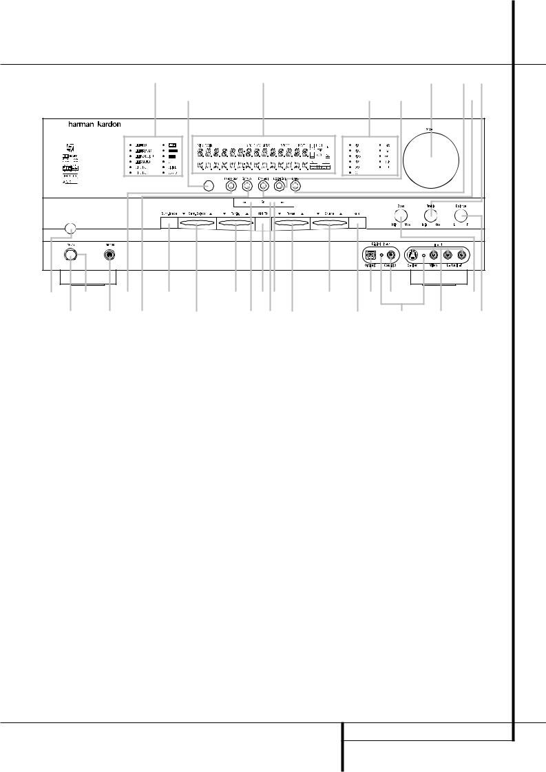
1Main Power Switch 2 System Power Control 3 Power Indicator
4 Headphone Jack
5 Surround Mode Group Selector
6 Speaker Selector
7 ‹ Button
8 Tone Mode
9 Surround Mode Selector )Tuning Selector
!Tuner Band Selector
1Main Power Switch: Press this button to apply power to the AVR 5550. When the switch is pressed in, the unit is placed in a Standby mode, as indicated by the orange LED 3 surrounding the System Power Control 2. This button MUST be pressed in to operate the unit. To turn the unit off completely and prevent the use of the remote control, this switch should be pressed until it pops out from the front panel so that the word “OFF” may be read at the top of the switch.
NOTE: This switch is normally left in the “ON” position.
2System Power Control: When the Main Power Switch 1is “ON,” press this button to turn on the AVR 5550; press it again to turn the unit off (to Standby). Note that the Power Indicator surrounding the switch 3will turn green when the unit is on.
3Power Indicator: This LED will be illuminated in orange when the unit is in the Standby mode to signal that the unit is ready to be turned on. When the unit is in operation, the indicator will turn green.
@Set Button |
ÒBalance Control |
#Preset Station Selector |
ÚTreble Control |
$› Button |
ÛDigital Select Button |
%Input Source Selector |
ÙChannel Select Button |
^RDS Selector |
ıVolume Control |
&Delay Adjust Selector |
ˆInput Indicators |
*Digital Optical 3 Input |
˜Main Information Display |
(Input/Output Status Indicators |
¯Remote Sensor Window |
ÓDigital Coax 3 Jack |
˘Surround Mode Indicators |
ÔVideo 4 Input/Output Jacks |
|
Bass Control |
|
4Headphone Jack: This jack may be used to listen to the AVR 5550’s output through a pair of headphones. Be certain that the headphones have a standard 6.3 mm stereo phone plug. Note that the main room speakers and all Preamp Outputs will automatically be turned off when the headphone jack is in use.
5Surround Mode Group Selector: Press this button to select the top-level group of surround modes. Each press of the button will select a major mode grouping in the following order:
Dolby Modes DTS Digital Modes VMAx Modes DSP Modes Stereo Modes Logic 7 Modes
Once the button is pressed so that the name of the desired surround mode group appears in the on-screen display and in the Lower Display Line
B, press the Surround Mode Selector 9to cycle through the individual modes available. For example, press this button to select Dolby modes, and then press the Surround Mode Selector
9to choose from the various mode options.
6 Speaker Selector: Press this button to begin the process of configuring the AVR 5550 for the type of speakers it is being used with. For complete information on configuring the speaker settings using the front-panel controls see page 21.
7‹ Button: When an adjustment is being made using the Channel Select Ùor Digital Select Ûbuttons, this button may be pressed to scroll through the available options.
8Tone Mode: Pressing this button enables or disables the Balance, Bass and Treble tone controls. When the button is pressed so that the words TONE IN appear in the Main Information Display ˜, the settings of the Bass
and Treble Úcontrols and of the Balance control Òwill affect the output signals. When the button is pressed so that the words TONE OUT appear in the Main Information Display ˜, the output signal will be “flat,” without any balance, bass or treble alteration, no matter how the actual Controls ÒÚare adjusted.
FRONT PANEL CONTROLS 5

Front Panel Controls
9Surround Mode Selector: Press this button to cycle through the individual surround modes available after the Surround Mode Group Selector 5was pressed (see item 5 above). Note that depending on the type of input, some modes are not always available. (See page 32 for more information about surround modes).
)Tuning Selector: Press the left side of the button to tune lower frequency stations and the right side of the button to tune higher frequency stations. When a station with a strong signal is reached, the TUNED indicator Iwill illuminate in the Main Information Display ˜
(see page 40 for more information on tuning stations).
!Tuner Band Selector: Pressing this button will automatically switch the AVR 5550 to the Tuner mode. Pressing it again will switch between the AM and FM frequency bands. Holding it pressed for 3 seconds will switch between stereo or mono receiving and automatic or manual tuning mode. When the button is pressed so that the AUTO Indicator Jlights, the tuner will search for the next station with an acceptable signal when the Tuning Selector )Kéis pressed. When the button is pressed so that the AUTO Indicator Jis not lit, each press of the Tuning Selector )Kéwill increase the frequency. (See page 40 for more information on using the tuner.)
@Set Button: When making choices during the setup and configuration process, press this button to enter the desired setting as shown in the Main Information Display ˜into the AVR 5550’s memory.
#Preset Stations Selector: Press this button to scroll up or down through the list of stations that have been entered into the preset memory. (See page 40 for more information on tuner programming.)
$ › Button: When an adjustment is being made using the Channel Select Ùor Digital Select Ûbuttons, this button may be pressed to scroll through the available options.
%Input Source Selector: Press this button to change the input by scrolling through the list of input sources.
^RDS Select Button: Press this button to display the various messages that are part of the RDS data system of the AVR 5550’s tuner. (See page 40 for more information on RDS).
& Delay Adjust Selector: Press this button to begin the process of adjusting the delay settings for Dolby surround modes. See page 25 for more information on delay adjustments.
*Digital Optical 3 Input: Connect the optical digital audio output of an audio or video product to this jack. When the Input is not in use, be certain to keep the plastic cap installed to avoid dust contamination that might degrade future performance.
(Input/Output Status Indicators: These LED indicators will normally light green to show that the front panel Video 4 A/V Ôjacks or the Coaxial 3 digital Ójack is operating as an input. When either of these jacks has been configured for use as an output, the indicator will turn red to show that the jack may be used for recording. (See page 21 for more information on configuring the front panel jacks as outputs, rather than inputs.)
ÓDigital Coax 3 Jack: This jack is normally used for connection to the output of portable audio devices, video game consoles or other products that have a coax digital jack. It may also be configured as an output jack, to feed a digital signal to a CD-R, MiniDisc or other digital recording device. (See page 21 for information on configuring the Digital Coax 3 Jack to an output.)
ÔVideo 4 Input/Output Jacks: These audio/video jacks may be used for temporary connection to video games or portable audio/ video products such as camcorders and portable audio players. They may also be configured as output jacks (also S-Video) to feed a signal to any recording Audio or Video device (see page 35 for more information).
Bass Control: Turn this control to modify the low frequency output of the left/right channels by as much as ±10dB. Set this control to a suitable position for your taste or room acoustics.
ÒBalance Control: Turn this control to change the relative volume for the front left/right channels.
NOTE: For proper operation of the surround modes this control should be at the midpoint or “12 o’clock” position.
ÚTreble Control: Turn this control to modify the high frequency output of the left/right channels by as much as ±10dB. Set this control to a suitable position for your taste or room acoustics.
ÛDigital Select Button: When playing a source that has a digital output, press this button to select between the Optical * and
Coaxial Ó Digital inputs (See page 33 for more information).
ÙChannel Select Button: Press this button to begin the process of trimming the channel output levels using an external audio source. (For more information on output level trim adjustment, see page 35).
ıVolume Control: Turn this knob clockwise to increase the volume, counterclockwise to decrease the volume. If the AVR is muted, adjusting volume control will automatically release the unit from the silenced condition.
ˆInput indicators: A green LED will light in front of the input that is currently being used as the source for the AVR 5550.
˜ Main Information Display: This display delivers messages and status indications to help you operate the receiver. (See pages 7 for a complete explanation of the Information Display.)
¯Remote Sensor Window: The sensor behind this window receives infrared signals from the remote control. Aim the remote at this area and do not block or cover it unless an external remote sensor is installed.
˘Surround Mode Indicators: A green LED will light in front of the surround mode that is currently in use.
6 FRONT PANEL CONTROLS
Front Panel Information Display
L K |
J I H |
G |
F |
|
A |
|
|
|
E |
|
|
|
|
|
B |
|
|
|
|
|
|
|
C |
D |
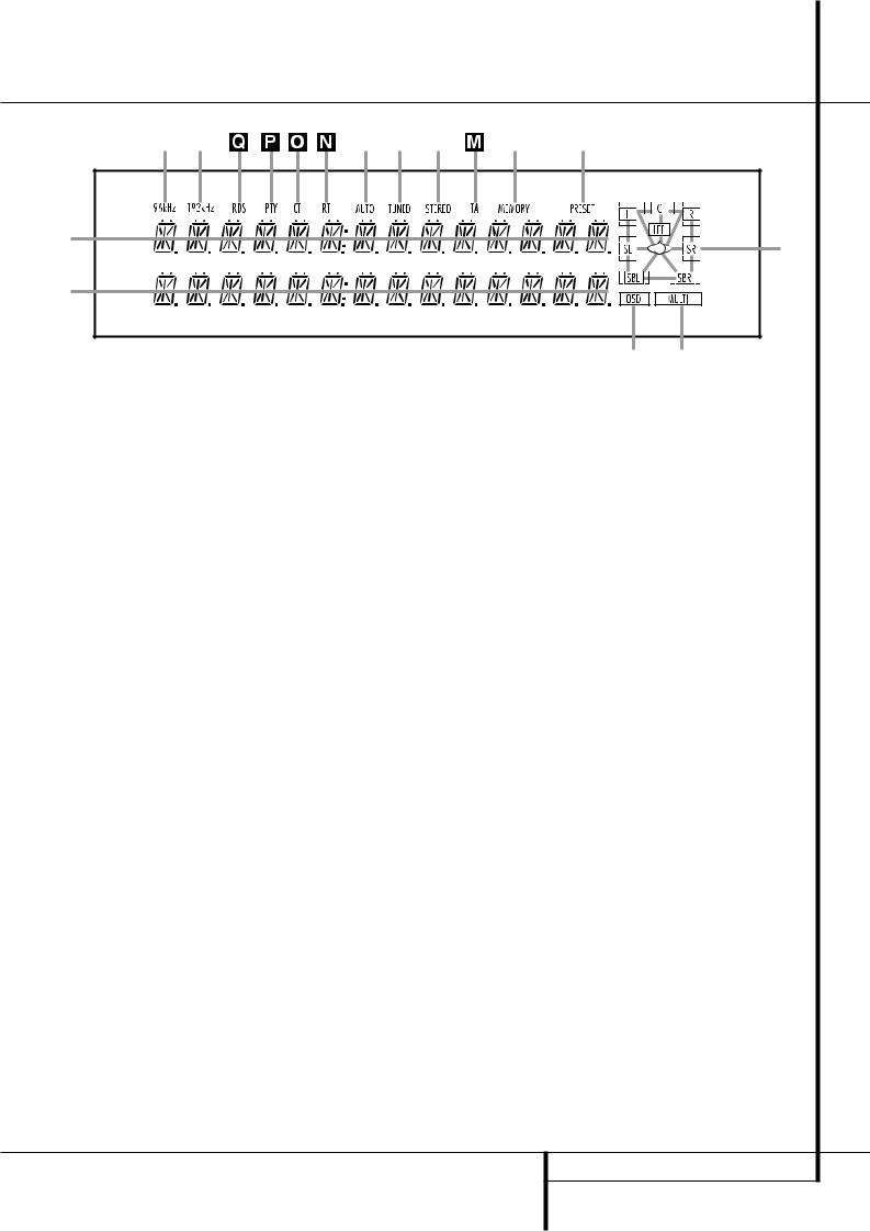
A Upper Display Line |
G Memory Indicator |
M Traffic Indicator |
B Lower Display Line |
H Stereo Indicator |
N Radiotext Indicator |
C OSD Indicator |
I Tuned Indicator |
O Clock Time Indicator |
D Multi Indicator |
J Auto Indicator |
P Program Type Indicator |
E Speaker/Channel Input Indicator |
K 192 kHz Indicator |
Q RDS Indicator |
F Preset Indicator |
L 96 kHz Indicator |
|
AUpper Display Line: Depending on the unit's status, a variety of messages will appear here. In normal operation, the current input source name will appear on this line.
BLower Display Line: Depending on the unit's status, a variety of messages will appear here. In normal operation, the current surround mode name will appear on this line.
COSD Indicator: When the OSD system is in use, this indicator lights to remind you that the other indicators in this display do not function when the On Screen Display is being used.
DMultiroom Indicator: This indicator lights when the multiroom system is active. Note that it will remain lit when the multiroom system is in use even though the main room system is in the Standby mode and all other indicators are dark. (See page 39 for more information on the Multiroom system.)
ESpeaker/Channel Input Indicators: These indicators are multipurpose, indicating either the speaker type selected for each channel or the incoming data-signal configuration. The left, center, right, right surround, left surround, right back surround and left back surround speaker indicators are composed of three boxes, while the subwoofer is a single box. The center box lights when a “Small” speaker is selected, and the two outer boxes light when “Large” speakers are selected. When none of the boxes are lit for the center, surround or subwoofer channels, no speaker has been selected for that position. (See page 21 for more information on configuring speakers.) The letters inside each of the center boxes display active input channels. For standard analog inputs, only the L and R will light, indicating a stereo input. When a digital source is playing, the indicators will light to display the channels begin received at the digital input. When the letters flash, the digital input has been interrupted. (See pages 24 and 34 for more information on the Channel Indicators).
FPreset Indicator: This indicator lights when the tuner is in use to show that the present number for the current station being listened to appears in the Upper Display Line. (See page 40 for more information on tuner presets.)
GMemory Indicator: This indicator flashes when entering presets and other information into the tuner’s memory.
HStereo Indicator: This indicator illuminates when an FM station is being tuned in stereo.
ITuned Indicator: This indicator illuminates when a station is being received with sufficient signal strength to provide acceptable listening quality.
JAuto Indicator: This indicator illuminates when the tuner’s Auto mode is in use.
K192 kHz Indicator: This indicator lights when the input source has a 192 kHz bit rate.
L96 kHz Indicator: This indicator lights when the input source has a 96 kHz bit rate.
MTA Traffic Announcement Indicator: This indicator illuminates if the RDS station tuned somtimes transmits traffic information (see page 40 for more information on RDS).
NRT Text Indicator: This indicator illuminates when the RDS station tuned is transmitting radiotext (RT) data.
OClock Time Indicator: This indicator illuminates when the RDS station tuned is transmitting the CT (clock time) code, indicating the current time of day.
PPTY Indicator: This indicator illuminates when the RDS station tuned is transmitting program type data, or during a PTY search.
QRDS Indicator: This indicator illuminates when the station tuned is transmitting RDS data.
FRONT PANEL INFORMATION DISPLAY 7
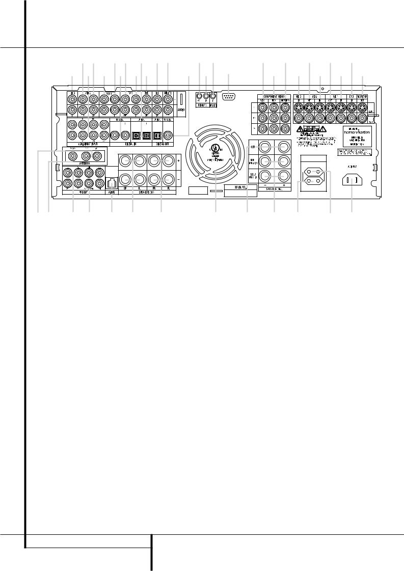
Rear Panel Connections
% # ! |
|
|
( ' & $ " |
* ) |
|
|
|
AVR 5550 |
AC OUTLETS
|
|
|
|
~230V/50Hz |
|
|
|
|
UNSWITCHED / 100W MAX |
|
|
|
|
230 V/50Hz |
|
|
|
|
SWITCHED / 50W MAX |
|
|
|
|
|
AM Antenna
FM Antenna
" Tape Inputs
# Tape Outputs
Subwoofer Output DVD Audio Inputs
CD Inputs
Multiroom Outputs
A-BUS Connector
' 8-Channel Direct Inputs
* Digital Audio Outputs
Video Monitor Outputs
DVD Video Inputs
Front Speaker Outputs
NOTE: To assist in making the correct connections for multichannel input/output and speaker connections, all connection jacks and terminals have been color coded in conformance with the latest CEA standards as follows:
Front Left: |
White |
Front Right: |
Red |
Center: |
Green |
Surround Left: |
Blue |
Surround Right: |
Gray |
Surround Back Left: |
Brown |
Surround Back Right: |
Tan |
Subwoofer (LFE): |
Purple |
Digital Audio: |
Orange |
Composite Video: |
Yellow |
Component Video “Y”: |
Green |
Component Video “Pr”: |
Red |
Component Video “Pb”: |
Blue |
AM Antenna: Connect the AM loop antenna supplied with the receiver to these terminals. If an external AM antenna is used, make connections to the AM and GND terminals in accordance with the instructions supplied with the antenna.
Center Speaker Outputs |
Video 3 Video Inputs |
Surround Speaker Outputs |
Video 2 Video Inputs |
Switched AC Accessory Outlet |
! Optical Digital Inputs |
Unswitched AC Accessory Outlet |
$ Coaxial Digital Inputs |
AC Power Cord Jack |
Video 2 Audio Outputs |
Video 2 Component Video Inputs |
Video 2 Audio Inputs |
Component Video Outputs |
( Video 3 Audio Inputs |
DVD Component Video Inputs |
% Video 1 Audio Inputs |
Remote IR Output |
& Video 1 Audio Outputs |
) Remote IR Input |
Preamp Outputs |
Multiroom IR Input |
Surround Back/Multiroom Speaker Outputs |
Video 1 Video Outputs |
RS-232 Port |
Video 1 Video Inputs |
Fan Vents |
Video 2 Video Outputs |
|
FM Antenna: Connect the supplied indoor or an optional external FM antenna to this terminal.
"Tape Inputs: Connect these jacks to the PLAY/OUT jacks of an audio recorder.
#Tape Outputs: Connect these jacks to the RECORD/INPUT jacks of an audio recorder.
Subwoofer Output: Connect this jack to the line-level input of a powered subwoofer. If an external subwoofer amplifier is used, connect this jack to the subwoofer amplifier input.
DVD Audio Inputs: Connect these jacks to the analog audio jacks on a DVD or other audio or video source.
CD Inputs: Connect these jacks to the analog output of a compact disc player or CD changer or any other audio source.
Multiroom Outputs: Connect these jacks to an optional audio power amplifier to listen to the source selected by the multiroom system in a remote room.
A-BUS Connector: Connect this jack to an optional A-BUS-certified remote room keypad or amplifier to extend the multiroom capabilities of your AVR 5550.
See page 18 for more information on A-BUS.
' 8-Channel Direct Inputs: These jacks are used for connection to source devices such as DVD-Audio or SACD players with discrete analog outputs. Depending on the source device in use, all eight jacks may be used, though in many cases only connections to the front left/right, center, surround left/right and LFE (subwoofer input) jacks will be used for standard 5.1 audio signals.
* Digital Audio Outputs: Connect these jacks to the matching digital input connector on a digital recorder such as a CD-R or MiniDisc recorder.
Video Monitor Outputs: Connect this jack to the composite and/or S-Video input of a TV monitor or video projector to view the on-screen menus and the output of any standard Video or
8 REAR PANEL CONNECTIONS

Rear Panel Connections
S-Video source selected by the receiver’s video switcher.
DVD Video Inputs: Connect these jacks to the composite or S-Video output jacks on a DVD player or other video source.
Front Speaker Outputs: Connect these outputs to the matching + or – terminals on your left and right speakers. In conformance with the new CEA color code specification, the White terminal is the positive, or "+" terminal that should be connected to the red (+) terminal on Front Left speaker with the older color coding, while the Red terminal is the positive, or "+" terminal that should be connected to the red (+) terminal on Front Right speaker. Connect the black (–) terminals on the AVR 5550 to the black
(–) terminals on the speakers. See page 15 for more information on speaker polarity.
Center Speaker Outputs: Connect these outputs to the matching + and – terminals on your center channel speaker. In conformance with the new CEA color code specification, the Green Terminal is the positive, or "+" terminal that should be connected to the red (+) terminal on speakers with the older color coding. Connect the black (–) terminal on the AVR to the black negative (–) terminal on your speaker. (See page 15 for more information on speaker polarity.)
Surround Speaker Outputs: Connect these outputs to the matching + and – terminals on your surround channel speakers. In conformance with the new CEA color code specification, the Blue terminal is the positive, or "+" terminal that should be connected to the red (+) terminal on the Surround Left speaker with older color coding, while the Gray terminal should be connected to the red (+) terminal on the Surround Right speaker with the older color coding. Connect the black (–) terminal on the AVR to the matching black negative (–) terminals for each surround speaker. (See page 15 for more information on speaker polarity.)
Switched AC Accessory Outlet: This outlet may be used to power any device that you wish to have turn on when the AVR 5550 is turned on with the System Power Control switch 2.
Unswitched AC Accessory Outlet: This outlet may be used to power any AC device. The power will remain on at this outlet regardless of whether the AVR 5550 is on or off (in Standby), provided that the Main Power switch 1is on.
Note: The total power consumption of all devices connected to the accessory outlets should not exceed 100 watts from the
Unswitched Outlet and 50 W from the Switched Outlet .
AC Power Cord Jack: Connect the AC power cord to this jack when the installation is complete. To ensure safe operation, use only the power cord supplied with the unit. If a replacement is required it must be of the same type and capacity.
Video 2 Component Video Inputs:
Connect the Y/Pr/Pb component video outputs of an HDTV Set-top convertor, satellite receiver, or other video source device with component video outputs to these jacks.
Monitor Component Video Outputs:
Connect these outputs to the component video inputs of a video projector or monitor. When a source connected to one of the two
Component Video Inputs is selected the signal will be sent to these jacks.
DVD Component Video Inputs: Connect the Y/Pr/Pb component video outputs of a DVD player to these jacks.
Note: All component inputs/outputs can be used for RGB signals too, in the same way as described for the Y/Pr/Pb signals, then connected to the jacks with the corresponding color.
RGB connection is not possible if the source outputs a separate sync signal (see page 16).
Remote IR Output: This connection permits the IR sensor in the receiver to serve other remote controlled devices. Connect this jack to the “IR IN” jack on Harman Kardon or other compatible equipment.
) Remote IR Input: If the AVR 5550’s frontpanel IR sensor is blocked due to cabinet doors or other obstructions, an external IR sensor may be used. Connect the output of the sensor to this jack.
Multiroom IR Input: Connect the output of an IR sensor in a remote room to this jack to operate the AVR 5550’s multiroom control system.
Video 1 Video Outputs: Connect these jacks to the RECORD/INPUT composite or S-Video jack on a VCR.
Video 1 Video Inputs: Connect these jacks to the PLAY/OUT composite or S-Video jacks on a VCR or other video source.
Video 2 Video Outputs: Connect these jacks to the RECORD/INPUT composite or S-Video jacks on a second VCR.
Video 3 Video Inputs: Connect these jacks to the PLAY/OUT composite or S-Video jacks on any video source.
Video 2 Video Inputs: Connect these jacks to the PLAY/OUT composite or S-Video jacks on a second VCR or other video source.
! Optical Digital Inputs: Connect the optical digital output from a DVD player, HDTV receiver, the S/PDIF output of a compatible computer sound card playing MP3 files or streams, LD player, MD player or CD player to these jacks. The signal may be either a Dolby Digital signal, a DTS signal, a 2 channel MPEG 1 signal, an MP3 or HDCD data stream or a standard PCM digital source.
$ Coaxial Digital Inputs: Connect the coax digital output from a DVD player, HDTV receiver, the S/PDIF output of a compatible computer sound card playing MP3 files or streams, LD player, MD player or CD player to these jacks. The signal may be either a Dolby Digital signal, DTS signal, a 2 channel MPEG 1 signal, an MP3 or HDCD data stream or a standard PCM digital source. Do not connect the RF digital output of an LD player to these jacks.
Video 2 Audio Outputs: Connect these jacks to the RECORD/INPUT audio jacks on a VCR or any Audio recorder.
Video 2 Audio Inputs: Connect these jacks to the PLAY/OUT audio jacks on a second VCR or other audio or video source.
(Video 3 Audio Inputs: Connect these jacks to the PLAY/OUT audio jacks on any audio or video source.
%Video 1 Audio Inputs: Connect these jacks to the PLAY/OUT audio jacks on a VCR or other audio or video source.
& Video 1 Audio Outputs: Connect these jacks to the RECORD/INPUT audio jacks on a VCR or any other Audio recorder.
Preamp Outputs: Connect these jacks to an optional, external power amplifier for applications where higher power is desired.
Surround Back/Multiroom Speaker Outputs: These speaker terminals are normally used to power the surround back left/surround back right speakers in a 7.1 channel system. However, they may also be used to power the speakers in a second zone, which will receive the output selected for a multiroom system.
To change the output fed to these terminals from the default of the Surround Back speakers to the Multiroom Output, you must change a setting in the Advanced Menu of the OSD system. See page 37 for more information on configuring this speaker output. In normal surround system use, the brown and black terminals are the surround back left channel positive (+) and negative (–) connections and the tan and black terminals are the surround back right positive
(+) and negative (–) terminals.
For multiroom use, connect the brown and black SBL terminals to the red and black connections on the left remote zone speaker and connect the
REAR PANEL CONNECTIONS 9

Rear Panel Connections
tan and black SBR terminals to the red and black terminals on the right remote zone speaker.
RS-232 Port: This jack is used to enable the AVR 5550 to be controlled by an external computer or programmable remote system that uses RS-232 commands. Due to the complexity of RS232 connections, we recommend that they be made by a trained and qualified custom installer. See page 18 for more information on the RS232 control port.
Fan Vents: These ventilation holes are the output of the AVR 5550’s airflow system. To ensure proper operation of the unit and to avoid possible damage to delicate surfaces, make certain that these holes are not blocked and that there is at least three inches of open space between the vent holes and any wooden or fabric surface.
10 REAR PANEL CONNECTIONS

Main Remote Control Functions
0Power Off Button
1IR Transmitter Window
2Program/SPL Indicator
3Power On Button
4Input Selectors
5AVR Selector
6AM/FM Tuner Select
76-Channel/8-Channel Direct Input
8Test Button
9Sleep Button
ASurround Mode Selector
BNight Mode
CChannel Select Button
D⁄/ ¤ Buttons
E‹ Button
FSet Button
GDigital Select
HNumeric Keys
ITuner Mode
JDirect Button
KTuning Up/Down
LOSD Button
MDolby Mode Select Button
NDTS Digital Mode Selector
OLogic 7 Mode Select Button
PTransport Controls
QLight Button
Skip Up/Down Buttons
Stereo Mode Select Button
DTS Neo:6 Mode Select
Macro Buttons
!RDS Selector Button
"Preset Up/Down
#Clear Button
$Memory Button
%Delay/Prev. Ch.
&› Button
'Speaker Select
(Multiroom
)Volume Up/Down
*SPL Indicator Select
+Learn Button
,Mute
-EzSet Sensor Microphone
NOTE: The function names shown here are each button’s feature when used with the AVR 5550. Most buttons have additional functions when used with other devices. See page 48-49 for a list of these functions.
MAIN REMOTE CONTROL FUNCTIONS 11
Main Remote Control Functions
IMPORTANT NOTE: The AVR 5550’s remote may be programmed to control up to seven devices, including the AVR 5550. Before using the remote, it is important to remember to press the Input Selector button 4that corresponds to the unit you wish to operate. In addition, the AVR 5550’s remote is shipped from the factory to operate the AVR 5550 and most Harman Kardon CD or DVD players and cassette decks. The remote is also capable of operating a wide variety of other products using the control codes that are part of the remote or by learning commands from other remotes. Before using the remote with other products, follow the instructions on pages 42-45 to program the proper codes for the products in your system.
It is also important to remember that many of the buttons on the remote take on different functions, depending on the product selected using the Input Selector Button 4. The descriptions shown here primarily detail the functions of the remote when it is used to operate the AVR 5550. (See page 45 for information about alternate functions for the remote’s buttons.)
0Power Off Button: Press this button to place the AVR 5550 or a selected device unit in the Standby mode. Note that when the AVR 5550 is switched off this will turn off the main room functions, but if the Multiroom system is activated, it will continue to function.
1IR Transmitter Window: Point this window towards the AVR 5550 when pressing buttons on the remote to make certain that infrared commands are properly received.
2Program/SPL Indicator: This three-color indicator is used to guide you through the process of programming the remote or learning commands from a remote into the AVR 5550’s remote code memory and it is also used as a level indicator when using the remote’s EzSet capabilities. (See page 26 for more information on setting output levels, and see page 42 for information on programming the remote.)
3Power On Button: Press this button to turn on the power to a device selected by pressing one of the Input Selectors 4(except Tape).
4Input Selectors: Pressing one of these buttons will perform three actions at the same time. First, if the AVR is not turned on, this will power up the unit. Next, it will select the source shown on the button as the input to the AVR. Finally, it will change the remote control so that it controls the device selected. After pressing one of these buttons you must press the AVR Selector button 5again to operate the AVR’s functions with the remote.
5AVR Selector: Pressing this button will switch the remote so that it will operate the AVR’s functions. If the AVR is in the Standby mode, it will also turn the AVR on.
6AM/FM Tuner Select: Press this button to select the AVR’s tuner as the listening choice. Pressing this button when the tuner is in use will select between the AM and FM bands.
76-Channel/8 Channel Direct Input:
Press this button to select the device connected to the 6-Channel Direct Inputs or the 8-Channel Direct Inputs ' (the input available will depend on the selection 5.1 or 6.1/7.1 made in the surround mode setting,
see page 23 for more information).
8Test Tone: Press this button to begin the sequence used to calibrate the AVR 5550’s output levels. (See page 26 for more information on calibrating the AVR 5550.)
9Sleep Button: Press this button to place the unit in the Sleep mode. After the time shown in the display, the AVR 5550 will automatically go into the Standby mode. Each press of the button changes the time until turn-off in the following order:
|
|
90 |
|
80 |
|
|
|
70 |
|
|
|
60 |
|
50 |
|
|
|
|
min |
|
min |
|
|
min |
|
|
min |
|
|
min |
|
||
|
|
|
|
|
|
|
|
|
|
|
|
|
|
|
|
|
|
40 |
|
30 |
|
|
20 |
|
|
10 |
|
|
OFF |
||||
|
|
|
|
|
|
|
|
|||||||||
|
|
min |
|
min |
|
|
min |
|
|
min |
|
|
||||
|
|
|
|
|
|
|
|
|
|
|
||||||
Hold the button pressed for two seconds to turn off the Sleep mode setting.
Note that this button is also used to change channels on your TV, VCR and Sat receiver when the appropriate source is selected, using the device Input Selectors 4.
ASurround Mode Selector: Press this button to select any of the HALL, THEATER or VMAx surround modes. Note that depending on the type of input, some modes are not always available. (See page 29 for more information about sur-round modes.) Note that this button is also used to tune channels on your TV, VCR and Sat receiver when the appropriate source is selected using the device Input Selector 4.
BNight Mode: Press this button to activate the Night mode. This mode is available only with Dolby Digital encoded sources, and it preserves dialog (center channel) intelligibilty at low volume levels (See page 25 for more information).
CChannel Select Button: This button is used to start the process of setting the
AVR 5550’s output levels with an external source. Once this button is pressed, use the ⁄/¤ buttons Dto select the channel being adjusted, then press the Set button F, followed by the ⁄/¤ buttons Dagain, to change the level setting. (See page 35 for more information.)
D⁄/¤ Buttons:These multipurpose buttons are used to change or scroll through items in the on-screen menus or on the front panel or to make configuration settings such as digital inputs or delay timing. When changing a setting, first press the button for the function or setting to be changed (e.g., press the Digital Select Button Gto change a digital input) and then press one of these buttons to scroll through the list of options or to increase or decrease a setting. The sections in this manual describing the individual features and functions contain specific information on using these buttons for each application.
When the AVR 5550 remote is being programmed for the codes of another device, these buttons are also used in the “Auto Search” process (See page 42 for more information on programming the remote.)
E‹ Button: This button is used to change the menu selection or setting during some of the setup procedures for the AVR 5550.
FSet Button: This button is used to enter settings into the AVR 5550’s memory. It is also used in the setup procedures for delay time, speaker configuration and channel output level adjustment.
GDigital Select: Press this button to assign one of the digital inputs !$*Óto a source. (See page 33 for more information on using digital inputs.)
HNumeric Keys: These buttons serve as a ten-button numeric keypad to enter tuner preset positions. They are also used to select channel numbers when TV, VCR or Sat receiver has been selected on the remote, or to select track numbers on a CD, DVD or LD player, depending on how the remote has been programmed.
ITuner Mode: Press this button when the tuner is in use to select between automatic tuning and manual tuning. When the button is pressed so that the AUTO indicator Jgoes out, pressing the Tuning buttons K)≠will move the frequency up or down in single-step increments. When the FM band is in use and the AUTO indicator Jis on, pressing this button will change to monaural reception making even weak stations audible or improving the audio performance with noisy stereo stations. (See page 40 for more information.)
JDirect Button: Press this button when the tuner is in use to start the sequence for direct entry of a station’s frequency. After pressing the button simply press the proper Numeric Keys Hto select a station (See page 40 for more information on the tuner).
12 MAIN REMOTE CONTROL FUNCTIONS
Main Remote Control Functions
KTuning Up/Down: When the tuner is in use, these buttons will tune up or down through the selected frequency band. If the Tuner Mode button Ihas been pressed or the Band button @on the front panel was held pressed so that the AUTO indicator Jis illuminated, pressing either of the buttons will cause the tuner to seek the next station with acceptable signal strength for quality reception. When the AUTO indicator Jis NOT illuminated, pressing these buttons will tune stations in single-step increments. (See page 40 for more information.)
LOSD Button: Press this button to activate the On Screen Display (OSD) system used to set up or adjust the AVR 5550’s parameters.
MDolby Mode Selector: This button is used to select one of the available Dolby Surround processing modes. Each press of this button will select one of the Dolby Pro Logic II modes, Dolby 3 Stereo or Dolby Digital. Note that the Dolby Digital mode is only available with a digital input selected and the other modes only as long as a Dolby Digital source is not playing (except Pro Logic II with Dolby Digital 2.0 recordings, see Note on page 7). See page 29 for the available Dolby surround mode options.
NDTS Digital Mode Selector: When a DTS source is in use the AVR 5550 will select the appropriate mode automatically and no other mode will be available. Pressing this button will display the mode currently selected by the AVR´s decoder, depending on the surround material played and the speaker setting (see item 6, page 5). When a DTS source is not in use, this button has no function. (See page 24, 29 for the available DTS options.)
OLogic 7 Selector: Press this button to select one of the available Logic 7 surround modes. (See page 29 for the available Logic 7 options.)
PTransport Control Buttons: These buttons do not have any functions for the AVR 5550, but they may be programmed for the forward/reverse play operation of a wide variety of CD or DVD players, and audio or videocassette recorders. (See page 42 for more information on programming the remote.)
QLight Button: Press this button to activate the remote’s built-in backlight for better legibility of the buttons in a darkened room.
Skip Up/Down Buttons: These buttons do not have a direct function with the AVR 5550, but when used with a compatibly programmed CD or DVD player/changer they will change the tracks on the disc currently being played.
Stereo Mode Select Button: Pressing this selector button cycles through the stereo modes, and it is also used to turn off all surround processing and place the unit in a traditional two-channel Stereo mode. The first press selects 5-Channel Stereo or 7-Channel Stereo, depending on the selection (5.1 or 6.1/7.1) made in the surround mode setting, see page 24, and the second selects “SURROUND OFF,” which is true Stereo.
DTS Neo:6 Mode Selector: Pressing this selector button cycles the AVR through the various DTS Neo:6 modes, which extract a fiveor seven-channel surround field from two-channel program material (from PCM source or analog input signal). The first press selects the last DTS Neo:6 surround mode that was in use, and each subsequent press selects the next mode in the following order:

 DTS Neo:6 MUSIC
DTS Neo:6
MOVIES
Macro Buttons: Press these buttons to store or recall a “Macro”, which is a pre-pro- grammed sequence of commands stored in the remote. (See page 44 for more information on storing and recalling macros.)
!RDS Select Button: Press this button to display the various messages that are part of the RDS data system of the AVR 5550’s tuner. (See page 40 for more information on RDS).
"Preset Up/Down: When the tuner is in use, press these buttons to scroll through the stations programmed into the AVR 5550’s memory. When CD or DVD is selected using the Input Selector button 4, these buttons may function as Slow Fwd/Rev (DVD) or ”+10” (CD, CDR).
#Clear Button: Press this button to clear incorrect entries when using the remote to directly enter a radio station’s frequency.
$Memory Button: Press this button to enter a radio station into the AVR 5550’s preset memory. After pressing the button the MEMORY indicator Gwill flash; you then have five seconds to enter a preset memory location using the Numeric Keys H. (See page 40 for more information.)
%Delay/Prev Ch.: Press this button to begin the process for setting the delay times used by the AVR 5550 when processing surround sound. After pressing this button, the delay times are entered by pressing the Set button Fand then using the ⁄/¤ buttons Dto change the setting. Press the Set button again to complete the process. (See page 25 for more information.)
&› Button: Press this button to change a setting or selection when configuring many of the AVR’s settings.
'Speaker Select: Press this button to begin the process of configuring the AVR 5550’s Bass Management System for use with the type of speakers used in your system. Once the button has been pressed, use the ⁄/¤ buttons Dto select the channel you wish to set up.
Press the Set Button Fand then select the speaker type (Large, Small or None) appropriate with the speaker in use. (See page 21 for more information.)
(Multi-Room: Press this button to activate the Multiroom system or to begin the process of changing the input or volume level for the second zone. (See page 39 for more information on the Multiroom system.)
)Volume Up/Down: Press these buttons to raise or lower the system volume.
*SPL Indicator Select: This button activates the AVR 5550’s EzSet function to quickly and accurately calibrate the AVR 5550’s output levels. During this sequence, EzSet will automatically adjust the output levels for all channels until they are equal, as shown by the Program Indicator 2lighting green for each channel. (See page 26 for more information on EzSet.)
+Learn Button: Press this button to begin the process of “learning” the codes from another product’s remote into the AVR 5550’s remote. (See page 43 for more information on using the remote’s learning function.)
,Mute: Press this button to momentarily silence the AVR 5550 or TV set being controlled, depending on which device has been selected. When the AVR 5550 remote is being programmed to operate another device, this button is pressed with the Input Selector button 4to begin the programming process. (See page 42 for more information on programming the remote.)
-EzSet Sensor Microphone: The sensor microphone for the EzSet microphone is behind these slots. When using the remote to calibrate speaker output levels using EzSet, be sure that you do not hold the remote in a way that covers these slots. (See page 26 for more information on using EzSet).
NOTE: With the press of any remote button the
Input Selector button 45associated with the botton pressed will briefly flash red to confirm the transmission of the command, as long as there is a function for that button with the device selected (see function list on pages 48, 49).
MAIN REMOTE CONTROL FUNCTIONS 13
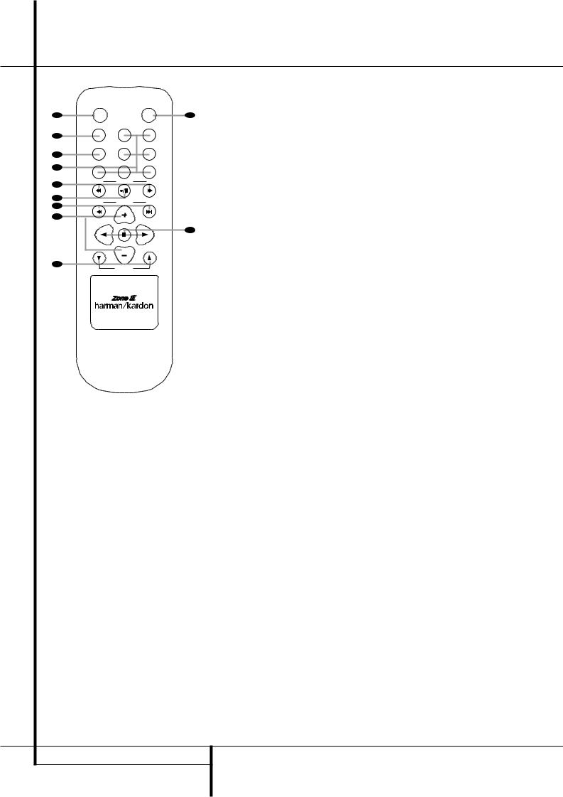
Zone II Remote Control Functions
POWER |
MUTE |
AOFF
AVR VID1 VID2
B |
|
|
|
|
|
AM/FM |
VID3 |
VID4 |
|
C |
|
|
|
|
D |
DVD |
CD |
TAPE |
|
|
|
|
||
E |
DN |
TUNING |
UP |
|
|
|
|
||
F |
DN |
PRESET |
UP |
|
G |
||||
|
|
|
||
H |
|
|
|
|
|
|
DISC SKIP |
|
|
|
|
DISC SKIP |
|
|
I |
|
VOLUME |
|
|
|
|
|
å Power Off
∫ AVR Selector
ç AM/FM Tuner Select
∂ Input Selectors
≠ Tuning Up/Down – Fast Play
ƒ Record/Pause
© Preset/Track Skip
˙ Disc Skip
î Volume Up/Down
∆ Play Forward/Reverse/Stop
˚ Mute
The Zone II remote may be used in either the same room where the AVR 5550 is located, or it may be used in a separate room with an option-
Kal infrared sensor that is connected to the AVR 5550’s Multi IR input jack .
åPower Off: When used in the room where the AVR 5550 is located, press this button to place the unit in Standby. When it is used in a remote room with a sensor that is connected to the Multi IR jack , this button turns the Multi-Room system off.
J∫AVR Selector: Press this button to turn on the AVR. The input in use when the unit was last on will be selected.
çAM/FM Tuner Select: Press this button to select the Tuner as the input to the Multiroom system. Press it again to change between the AM and FM bands.
∂Input Selectors: When the AVR is off, press one of these buttons to turn the unit on and to select a specific input. When the unit is already in use, pressing one of these buttons will change the input.
≠Tuning Up/Down – Fast Play: These buttons may be used to change the frequency of the tuner. These buttons may also control the Fast Play or Fast Reverse functions of compatible Harman Kardon CD, DVD or cassette decks in the same room, or from a remote room when an IR link is connected to the AVR 5550.
ƒRecord/Pause: Press this button to activate the Record or Pause function on compatible Harman Kardon CD, DVD or Cassette Deck products.
NOTE: The Zone II remote may be used in either the same room where the AVR 5550 is located, or it may be used in a separate room with an optional infrared sensor that is connected to the AVR 5550’s Multi IR input jack f. When it is used in the same room as the AVR 5550, it will control the functions of the AVR 5550 or any compatible Harman Kardon products in that room. When it is used in a separate room via a sensor connected to the Multi IR Jack f, the buttons for power, input source, volume and
©Preset Up/Down – Track Skip: When the AVR’s tuner is selected as the input source, these buttons will move up or down through the list of stations that have been stored in the preset memory. When a CD or DVD player is selected, these buttons activate the forward or reverse track or chapter skip functions.
˙Disc Skip: Press this button to change discs on compatible Harman Kardon CD or DVD changers.
îVolume Up/Down: When used in the room where the AVR 5550 is located, press this button to raise or lower the volume in that room. When it is used in a remote room with a sensor that is connected to the Multi IR Jack, this button will raise or lower the volume in the remote room.
∆Play Forward/Reverse/Stop: Press these buttons to control compatible Harman Kardon CD, DVD or cassette players.
˚Mute: When used in the room where the AVR 5550 is located, press this button to temporarily silence the unit. When it is used in a remote room with a sensor that is connected to the Multi IR Jack , this button will temporarily silence the feed to the remote room only. Press the button again to return to the previous volume level.
Important Note: No matter in which room the Zone II remote is used, as with the main remote it is important to remember to press the Input Selector button ∂that corresponds to the unit you wish to operate befor you change the device to be controlled.
mute will control the source and volume for the second zone, as connected to the Multi Out Jacks •. (See page 39 for complete information on using the Multiroom system.)
14 ZONE II REMOTE CONTROL FUNCTIONS
Installation and Connections
After unpacking the unit, and placing it on a solid surface capable of supporting its weight, you will need to make the connections to your audio and video equipment.
Audio Equipment Connections
We recommend that you use high-quality interconnect cables when making connections to source equipment and recorders to preserve the integrity of the signals.
When making connections to audio source equipment or speakers it is always a good practice to unplug the unit from the AC wall outlet. This prevents any possibility of accidentally sending audio or transient signals to the speakers that may damage them.
1. Connect the analog output of a CD player to the CD inputs .
NOTE: When the CD player has both fixed and variable audio outputs it is best to use the fixed output unless you find that the input to the receiver is so low that the sound is noisy, or so high that the signal is distorted.
2.Connect the analog Play/Out jacks of a cassette deck, MD, CD-R or other audio recorder to the Tape Input jacks ". Connect the analog Record/In jacks on the recorder to the Tape Output jacks # on the AVR 5550.
3.Connect the digital output of any digital sources such as a CD or DVD changer or player, advanced video game, a digital satellite receiver, HDTV tuner or digital cable set-top box or the output of a compatible computer sound card to the Optical and Coaxial Digital Inputs
!$*Ó.
4.Connect the Coaxial or Optical Digital Outputs *on the rear panel of the AVR to the matching digital input connections on a CD-R or MiniDisc recorder.
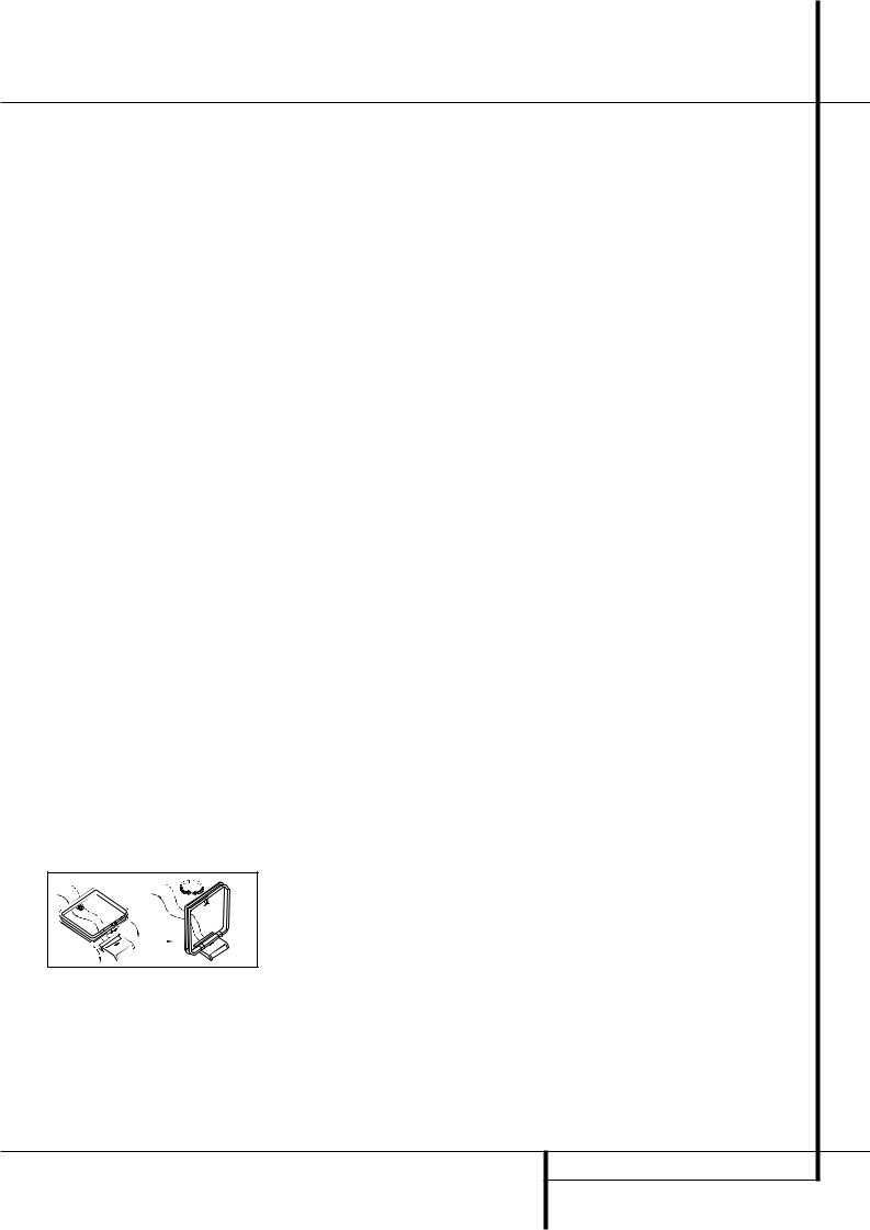
5.Assemble the AM Loop Antenna supplied with the unit as shown below. Connect it to the AM and GND screw terminals .
6. Connect the supplied FM antenna to the FM
(75 ohm) connection . The FM antenna may be an external roof antenna, an inside powered or wire lead antenna or a connection from a cable system. Note that if the antenna or connection uses 300-ohm twin-lead cable, you should use a 300-ohm-to-75-ohm adapter to make the connection.
7. Connect the front, center and surround speaker outputs to the respective speakers.
To assure that all the audio signals are carried to your speakers without loss of clarity or resolution, we suggest that you use high-quality speaker cable. Many brands of cable are available and the choice of cable may be influenced by the distance between your speakers and the receiver, the type of speakers you use, personal preferences and other factors. Your dealer or installer is a valuable resource to consult in selecting the proper cable.
Regardless of the brand of cable selected, we recommend that you use a cable constructed of fine, multistrand copper with an area greater than 2 mm2.
Cable with an area of 1.5 mm2 may be used for short runs of less than 4 m. We do not recommend that you use cables with an area less than 1mm2 due to the power loss and degradation in performance that will occur.
Cables that are run inside walls should have the appropriate markings to indicate listing with any appropriate testing agency standards. Questions about running cables inside walls should be referred to your installer or a licensed electrician who is familiar with the applicable local building codes in your area.
When connecting wires to the speakers, be certain to observe proper polarity. Note that the positive (+) terminal of each speaker connection now carries a specific color code as noted on page 9. However, most speakers will still use a red terminal for the postive (+) connection. Connect the “negative” or “black” wire to the same terminal on both the receiver and the speaker.
NOTE: While most speaker manufacturers adhere to an industry convention of using black terminals for negative and red ones for positive, some manufacturers may vary from this configuration. To assure proper phase and optimal performance, consult the identification plate on your speaker or the speaker’s manual to verify polarity. If you do not know the polarity of your speaker, ask your dealer for advice before proceeding, or consult the speaker’s manufacturer.
We also recommend that the length of cable used to connect speaker pairs be identical. For example, use the same length piece of cable to connect the front-left and front-right or surround-left and surround-right speakers, even if the speakers are a different distance from the AVR 5550.
8.Connections to a subwoofer are normally made via a line level audio connection from the Subwoofer Output to the line-level input of a subwoofer with a built-in amplifier. When a passive subwoofer is used, the connection first goes to a power amplifier, which will be connected to one or more subwoofer speakers. If you are using a powered subwoofer that does not have line-level input connections, follow the instructions furnished with the speaker for connection information.
9.If an external multi-channel audio source with 5.1 or 7.1 outputs such as an external digital processor/decoder, DVD-Audio or SACD player is used, connect the outputs of that device to the
8-Channel Direct Inputs '.
Video Equipment Connections
Video equipment is connected in the same manner as audio components. Again, the use of highquality interconnect cables is recommended to preserve signal quality. To ensure best video performance S-Video sources should be connected to the AVR 5550 only with their S-Video In/ Outputs, not with their composite video connectors too.
1.Connect a VCR’s audio and video Play/Out jacks to the Video 1 or Video 2 In jacks % on the rear panel. The Audio and Video Record/In jacks on the VCR should be connected to the Video 1 or Video 2 Out jacks
& on the AVR 5550.
2.Connect the analog audio and video outputs of a satellite receiver, cable TV converter or television set or any other video source to the Video
3( jacks.
3.Connect the analog audio and video outputs of a DVD or laser disc player to the DVD jacks
.
4.Connect the digital audio outputs of a CD, MD or DVD player, satellite receiver, cable box or HDTV converter to the appropriate Optical or
Coaxial Digital Inputs !$*Ó.
5.Connect the Composite and S-Video (if
S-Video device is in use) Monitor Output jacks on the receiver to the composite and S-Video input of your television monitor or video projector.
6. If your DVD player and monitor both have component video connections, connect the component outputs of the DVD player to the DVD Component Video Inputs . Note that even when component video connections are used the audio connections must still be made to either the analog DVD Audio Inputs or any of the
Coaxial or Optical Digital Input jacks !$.
INSTALLATION AND CONNECTIONS 15

Installation and Connections
7.If another component video device is available, connect it to the Video 2 Component Video Input jacks . The audio connections for this device should be made to either the Video 2 Input jacks or any of the Coaxial or Optical Digital Input jacks !$.
8.If the component video inputs are used, connect the Component Video Output to the component video inputs of your TV, projector or display device.
9.If you have a camcorder, video game or other audio/video device that is connected to the AVR on a temporary, rather than permanent basis, connect the audio, video and digital audio outputs of that device to the Front Panel Inputs *ÓÔ. A device connected to the Video 4 jacks Ôis selected as the Video 4 input, and connected to the digital jacks *Óit is selected as "Optical 3" or "Coaxial 3" input. (See page
21for more information on input configuration.)
Video Connection Notes:
•Y/Pr/Pb Component, RGB (see page 17),
or Composite video signals may only be viewed in their native formats and will not be converted to the other formats. S-Video signals will be converted to composite signal. The OSD can be viewed on the TV screen in any case, with Video or S-Video input selected on the TV.
•When the component video jacks are used, the on-screen menus will not be visible. You must switch to the standard composite or S-Video input on your TV to view those menus.
•All component inputs/outputs can be used for RGB signals too, in the same way as described for the Y/Pr/Pb signals, then connected to the jacks with the corresponding color.
But this is only correct as long as only the three RGB video signals are output by the video source, with a sync signal in the "G" signal only, without any sync signal output separately by the source.
SCART A/V Connections
For the connections described above your video device needs RCA (cinch) connectors or/and S- Video connectors for all Audio and Video signals: Any normal video device (Not SVHS or High 8) for only playback needs 3 RCA jacks, VCRs for record and playback even 6 RCA jacks. Any S-Video device (SVHS, High 8) needs 2 RCA (Audio) and 1 S-Video jack (Video), if it´s a playback unit, or 4 RCA (Audio In/Out) and
2 S-Video (Video In/Out) jacks, if it´s a recording VCR.
Many european video devices are equipped with RCA (Cinch) or S-Video jacks only partially, not for all audio and video in/outputs needed as described above, but with a so called Scart or Euro-AV connector (almost rectangular jack with 21 pins, see drawings on next page).
In that case the following Scart to Cinch adapters or cables are needed:
•Units for playback, such as satellite receivers, camcorders, DVD or LD players, need an adapter from Scart to 3 RCA plugs, see fig. 1 (normal video devices) or from Scart to 2 RCA+1 S-Video plugs, see fig. 4 (S-Video devices).
•HiFi VCRs need an adapter from Scart to 6 RCA plugs, see fig. 2 (normal video), or from Scart to 4 Audio+2S-Video jacks, see fig. 5 (S-Video VCR). Read carefully the instruction attached to the adapter to find which of the six plugs is used for the record signal to the VCR (connect with the AVR´s Out jacks) and for the playback signal from the VCR (connect with the AVR´s In jacks). Do not misconnect Audio and Video signals. Don´t hesitate to consult your dealer, if you are uncertain.
•If you use only normal video devices the TV monitor needs an adapter from 3 RCA plugs to Scart (fig. 3) only. If also S-Video devices are used an adapter from 2 RCA+1S-Video plugs to Scart is needed additionally (fig. 6), connected to the SCART input on your TV that is provided for S-Video.
Note that only the video plugs (the "yellow" cinch plug in fig. 3 and the S-Video plug in fig. 6) must be connected to the TV Monitor Output , and the volume on the TV must be reduced to minimum.
Important Note for Adapter Cables:
If the cinch connectors of the adapter you’ll use are labeled, connect the Audio and Video ”In” plugs with the corresponding Audio and Video ”In” jacks on the AVR 5550 (and with a VCR connect the ”Out” plugs to the ”Out” jacks on the AVR). Note that with some adapter types it may be just turned around: If no signal is audible/ visible when the VCR is playing connect the “Out” plugs to the ”In” jacks on the AVR and turned around. If the adapter plugs are not labeled in that way, pay attention to the signal flow directions as shown in the diagrams above and in the instruction attached to the adapter. If uncertain, don’t hesitate to consult your dealer.
Important Notes for S-Video connections:
1.Only the S-Video In/Out of S-Video devices must be connected to the AVR, NOT both, normal video and S-Video In/Outputs (except the TV, see item below).
When both connections are made, only the S-Video signal will be viewed on the screen.
2.Like most common AV units the AVR 5550 does not convert the Video signal to S-Video, only vice versa. Thus both connections must be made from the AVR 5550 to the TV if both, Video and S-Video sources, are used, and the appropriate input on the TV must be selected.
16 INSTALLATION AND CONNECTIONS
 Loading...