


8” x 12” lathe
44859
Assembly and operating instructions
Distributed exclusively by Harbor Freight Tools®.
3491 Mission Oaks Blvd., Camarillo, CA 93011
Visit our website at: http://www.harborfreight.com
Read this material before using this product. Failure to do so can result in serious injury. Save this manual.
Copyright© 2001 by Harbor Freight Tools®. All rights reserved. No portion of this manual or any artwork contained herein may be reproduced in any shape or form without the express written consent of Harbor Freight Tools. Diagrams within this manual may not be drawn proportionally. Due to continuing improvements, actual product may differ slightly from the product described herein. Tools required for assembly and service may not be included.
For technical questions or replacement parts, please call 1-800-444-3353.
Revised 09g
|
Specifications |
|
ITEM |
|
DESCRIPTION |
|
|
|
Power |
|
110VAC, 60 Hz, 550 watts |
|
|
|
Motor |
|
3/4 HP |
|
|
|
Distance between Centers |
|
12 inches |
|
|
|
Swing over Bed |
|
8 inches |
|
|
|
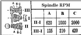
Spindle Step Speeds |
|
125, 210, 420, 620, 1000, 2000 RPM |
|
|
|
Spindle Bore |
|
3/4 inch |
|
|
|
Spindle Taper |
|
MT3 |
|
|
|
Tailstock Taper |
|
MT2 |
|
|
|
Chuck Capacity |
|
4 inch, 3-jaw; reversing jaws |
|
|
|
Cross Slide Travel |
|
4-1/2 inches |
|
|
|
Tool Slide Travel |
|
2-3/4 inches |
|
|
|
Slide Scale |
|
0.001 inch per mark tool |
|
|
|
Metric Thread Pitches |
|
10 (0.4 ~ 3.0 mm) |
|
|
|
SAE Thread Pitches |
|
12 (8 ~ 40 TPI) |
|
|
|
Accessories |
|
- 3 reverse jaws for chuck |
|
|
- Chuck wrench |
|
|
- Dead centers MT2 and MT3 |
|
|
- Wrenches: 10-12 open end, 14-17 open end |
|
|
17-19 open end, 45-52 round nut, tool post |
|
|
- Hex wrenches: 3, 4, 5, 6mm |
|
|
- 2 Drive Belts |
|
|
- Threading gear set |
|
|
|
Weight |
|
254 lb. |
|
|
|
NOTE: The Splash Guard shown in the cover page photo is not included. It can be ordered from Harbor Freight Tools using SKU 26962.
Save This Manual
You will need the manual for the safety warnings and precautions, assembly instructions, operating and maintenance procedures, parts list and diagram. Keep your invoice with this manual. Write the invoice number on the inside of the front cover. Keep the manual and invoice in a safe and dry place for future reference.
Safety Warnings and Precautions
WARNING: When using tool, basic safety precautions should always be followed to reduce the risk of personal injury and damage to equipment.
Read all instructions before using this tool!
1.Keep work area clean. Cluttered areas invite injuries.
2.Observe work area conditions. Do not use machines or power tools in damp or wet locations. Don’t expose to rain. Keep work area well lighted. Do not use electrically powered tools in the presence of flammable gases or liquids.
07h, 07l
SKU 44859 |
Page 2 |
3.Keep children away. Children must never be allowed in the work area. Do not let them handle machines, tools, or extension cords.
4.Store idle equipment. When not in use, tools must be stored in a dry location to inhibit rust. Always lock up tools and keep out of reach of children.
5.Do not force tool. It will do the job better and more safely at the rate for which it was intended. Do not use inappropriate attachments in an attempt to exceed the tool capacity.
6.Use the right tool for the job. Do not attempt to force a small tool or attachment to do the work of a larger industrial tool. There are certain applications for which this tool was designed. Do not modify this tool and do not use this tool for a purpose for which it was not intended.
7.Dress properly. Do not wear loose clothing or jewelry as they can be caught in moving parts. Protective, electrically non-conductive clothes and non-skid footwear are recommended when working. Wear restrictive hair covering to contain long hair.
8.Use eye and ear protection. Always wear ANSI approved impact safety goggles. Wear a full face shield if you are producing metal filings or wood chips. Wear an ANSI approved dust mask or respirator when working around metal, wood, and chemical dusts and mists.
9.Do not overreach. Keep proper footing and balance at all times. Do not reach over or across running machines.
10.Maintain tools with care. Keep tools sharp and clean for better and safer performance. Follow instructions for lubricating and changing accessories. Inspect tool cords periodically and, if damaged, have them repaired by an authorized technician. The handles must be kept clean, dry, and free from oil and grease at all times.
11.Disconnect power. Unplug tool when not in use.
12.Remove adjusting keys and wrenches. Check that keys and adjusting wrenches are removed from the tool or machine work surface before plugging it in.
13.Avoid unintentional starting. Be sure the switch is in the Off position when not in use and before plugging in.
14.Stay alert. Watch what you are doing, use common sense. Do not operate any tool when you are tired.
15.Check for damaged parts. Before using any tool, any part that appears damaged should be carefully checked to determine that it will operate properly and perform its intended function. Check for alignment and binding of moving parts; any broken parts or mounting fixtures; and any other condition that may affect proper operation. Any part that is damaged should be properly repaired or replaced by a qualified technician.
Do not use the tool if any switch does not turn On and Off properly.
16.Guard against electric shock. Prevent body contact with grounded surfaces such as pipes, radiators, ranges, and refrigerator enclosures.
17.Replacement parts and accessories. When servicing, use only identical
SKU 44859 |
Page 3 |
replacement parts. Use of any other parts will void the warranty. Only use accessories intended for use with this tool. Approved accessories are available from Harbor Freight Tools.
18.Do not operate tool if under the influence of alcohol or drugs. Read warning labels on prescriptions to determine if your judgment or reflexes are impaired while taking drugs. If there is any doubt, do not operate the tool.
19.Use proper size and type extension cord. If an extension cord is required, it must be of the proper size and type to supply the correct current to the tool without heating up.
Otherwise, the extension cord could melt and catch fire, or cause electrical damage to the tool. This tool requires use of an extension cord of 0 to 12 amps capability (up to 50 feet), with wire size rated at 16 AWG. Longer extension cords require larger size wire. If you are using the tool outdoors, use an extension cord rated for outdoor use
(signified by “WA” on the jacket).
21.Maintenance. For your safety, service and maintenance should be performed regularly by a qualified technician.
22.Know your power tool. Read and understand this assembly and operating manual, and labels affixed to the tool. Learn it’s application and limitations, as well as the specific potential hazards particular to this tool.
23.Ground the tool. This tool is equipped with an approved 3-conductor cord and 3- prong grounding type plug to fit a grounding type receptacle. The green wire in the cord is the grounding wire. Never connect the green wire to a live terminal.
24.Use safety guards. Keep guards in place, in working order, and in proper adjustment and alignment.
25.Secure workpiece. Use clamps or a vise to hold workpiece when practical. Keep both hands free to operate tool.
26.Direction of Feed. Feed workpiece into the blade or cutter against the direction of the rotation.
Note: Performance of this tool may vary depending on variations in local line voltage. Extension cord usage may also affect tool performance.
Warning:The warnings, cautions, and instructions discussed in this instruction manual cannot cover all possible conditions and situations that may occur. It must be understood by the operator that common sense and caution are factors which cannot be built into this product, but must be supplied by the operator.
Unpacking
When unpacking, check to make sure that all the parts are included. Refer to the Accessories list in the Specifications table, and the Parts List.
If any parts are missing or broken, please call Harbor Freight Tools at the number on the cover of this manual as soon as possible.
SKU 44859 |
07h |
Page 4 |
|
|
Installation
1.Carefully place the Lathe on a sturdy, level work table with sufficient light.
2.Use appropriate hardware (not included) in the mounting holes of the lathe base, to properly secure the lathe. The work table must also be properly mounted to the floor.
3.Before operation, verify that the slide, worktable, and spindle can move, and are not locked in place.
4.Clean machine with nonflammable solvent and oil the machine according to the lubrication requirements (see Lubrication section) before running the machine.
Operation
This 8 x 12 inch Lathe is capable of machining metal and nonmetallic stock by cutting, drilling, and milling. It can cut circular surfaces, both inside and out, cones, mill planes or grooves, and other cutting functions depending on the tools used. It can also create SAE
and metric threads. |
|
B |
|
|
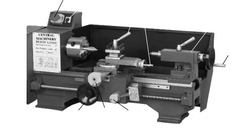
Controls |
|
A |
|
|
|
E |
F |
|
|
|
|
H |
||
|
|
|
||
|
|
|
|
I |
|
|
|
|
|
|
|
|
|
|
D C G
NOTE: The Splash Guard shown in the photo above is not included. It can be ordered using SKU 26962.
|
ITEM |
NAME |
USAGE |
ASSY NO. |
|
|
|
|
|
|
|
|
A |
Reversing Switch |
Change rotation direction of the spindle |
200 |
|
|
|
|
|
|
|
|
B |
Master Switch |
Turn machine power On and Off |
200 |
|
|
|
|
|
|
|
|
C |
Turn Lever |
Moves saddle transversely |
500 |
|
|
|
|
|
|
|
|
D |
Turn Lever |
Moves saddle longitudinally |
600 |
|
|
|
|
|
|
|
|
E |
Straight Lever |
Clamps the square tool rest |
400 |
|
|
|
|
|
|
|
|
F |
Straight Lever |
Moves the square tool rest carriage longitudinally |
400 |
|
|
|
|
|
|
|
|
G |
Straight Lever |
Controls apron clasp nut |
600 |
|
|
|
|
|
|
|
|
H |
Straight Lever |
Controls tailstock sleeve |
300 |
|
|
|
|
|
|
|
|
I |
Turn Lever |
Moves tailstock sleeve longitudinally |
300 |
|
|
|
|
|
|
5 |
SKU 44859 |
|
07h |
Page |
||
Lathe Safety Precautions
1.Keep fingers away from revolving parts and cutting tools while in operation.
2.Never force cutting action.
3.Never perform an abnormal or little used operation without study and use of adequate blocks, jigs, stops, and fixtures.
4.Verify proper cutting speed for the material being cut, and any special operation, in a machinery shop handbook.
5.Do not open drive cover while in operation.
6.Always remove chuck key from chuck.
7.Do not attempt to adjust or remove tools when lathe is in operation.
8.Always keep cutting tools sharp.
Cutting Procedures
The instructions that follow are basic operational procedures. It is assumed that the operator understands lathe operation and it’s capabilities.
1.Rotate Turn Lever (C) counterclockwise to move the saddle outward.
2.Place the workpiece in the chuck, center, and secure with the chuck key.
3.Loosen the Straight Lever (H) and then rotate the Turn Lever (I) clockwise to engage the Dead Center tool into the end of the workpiece. Tighten Straight Lever (H) again.
4.Select the desired tool set and place it into the tool rest. Align the tool nose to the spindle centerline, then tighten.
5.Open the Gear Box and verify that the proper
speed is engaged.
Typically, the harder the metal workpiece, the faster the spindle speed.
6.Set the desired feed amount according to the type of stock, workpiece dimensions, and the type of cut.
7.Close the Gear Box.
8.Open the safety cover over the On / Off switch and press the green On button. Verify that the lathe head and feed amount is correct.
9.Align the tool nose on the workpiece where the cut is to begin.
10.Rotate the Turn Lever (C) clockwise to move the saddle transversely, moving the tool nose into the workpiece for cutting.
11.When the cut is complete, press the red Off button.
SKU 44859 |
Page 6 |
Machining Cylinders
1.Repeat the cutting procedure steps 1 through 8, listed on the previous page.
2.Rotate Turn Lever (D) clockwise and move the saddle to the right of the workpiece.
3.Rotate Turn Lever (C) clockwise until the desired depth of cut is reached on the far right surface of the work piece.
4.Press down on the Straight Lever (G) to engage apron clasp nut over the Gear Shaft.
The tool will automatically move from right to left while cutting the workpiece.
5.When the cut is complete, press the red Off button.
Optionally, you can turn the Reverse switch to have the tool go over the same cut in the opposite direction (left-to-right). This will clean and smooth the previous cut.
6.When the cut is complete, press the red Off button.
Machining Cones
Manually
This operation is similar to machining cylinders with the following differences.
1.To manually cut a cone, determine the taper requirement and turn the small cutter rest to the desired slope on the workpiece. Retighten the cutter rest.
2.Press the green On button to start the lathe.
3.Turn the Straight Lever (F) clockwise to make the cut.
Automatically
1.To automatically cut a cone, determine the taper requirement and turn the small cutter rest to the desired slope on the workpiece. Retighten the cutter rest.
2.Horizontally move the tailstock from the spindle centerline to the required slope on the far right surface of the work piece.
3.Press the green On button to start the lathe.
4.Press down on the Straight Lever (G) to engage apron clasp nut over the Gear Shaft. The tool will automatically move from right to left while cutting the workpiece.
5.Repeat steps 2 through 4 until the desired cone size is cut.
6.When the cut is complete, press the red Off button.
Machining Threads
The Gear Box is composed of the change gears, shaft bolt, fixing shaft bolt, and square nut. The change gear box is fixed on the left support of the leadscrew (101). To cut threads, select the proper change gears for the desired thread type (see Thread Formula Table), and engage with approximately 0.1 mm tolerance. Tighten Screw (835).
SKU 44859 |
Page 7 |

The Fixed Shaft Bolt (825) under the spindle is used for right hand cutting and threading.
The set of Fixed Shaft Bolts in the accessory kit is used in combination with the original set of Shaft Bolts to reverse the rotation of the long leadscrew for left-handed threading and cutting.
The change gear for metric or inch threading is selected according to the Thread to Gear formula and table. The feed amount depends on the material to be cut, the surface roughness, and finish requirements. If the two settings “0.1 and 0.2”, of the Gear table do not meet the requirement, you can add or change gears. The same is true if the number of teeth listed in the Gear table do not coincide with the calculated number of teeth. In this case, use gears with similar number of teeth. In doing so, however, the following relationship of the driving shaft must be met: Z3+Z4+>Z2+Z5. Otherwise, the addendum of circles A2 and Z5 will hit each other.
The left formula below is an example of 0.3 mm spindle round. The right formula is an example for 8 threads per inch.
The Thread to Gear settings table on the following page allows you to select the number of threads per inch or millimeter, and which gears need to be used.
SKU 44859 |
Page 8 |

Rest Accessories
The Follow Rest (not supplied) is mainly used for cutting long and thin shaft pieces to ensure no bending takes place during cutting. It also provides a better finish surface as a result of less vibration. The Steady Rest (not supplied) provides a similar function as with the Follow Rest. The difference being that the Steady Rest is fixed on the bed guides, and does not follow the movement of the cutting tool. Both rests can be purchased from Harbor Freight Tools.
Maintenance
General
1.Unplug power cord from receptacle when not in use.
2.Using compressed air, blow off all dirt and particles after using.
3.Keep all tools sharp.
4.Cover Lathe when not in use.
5.Periodically, check all bolts and nuts for tightness.
Lubrication
Lubricate the Lathe daily using an appropriate machine oil from a forced-feed oil can.
SKU 44859 |
Page 9 |
ITEM |
PART TO BE LUBRICATED |
LUBE POINT |
|
|
|
See lubrication location illustration on next page |
|
|
|
|
|
1 |
Fix bolt of intermediate gear |
Oil Cup |
|
|
|
2 |
Leadscrew support |
Oil Cup |
|
|
|
3 |
Cutter rest screw |
Oil Cup |
|
|
|
4 |
Cutter rest carriage |
Oil Cup |
|
|
|
5 |
Tailstock sleeve |
Oil Cup |
|
|
|
6 |
Tailstock leadscrew |
Oil Cup |
|
|
|
7 |
Leadscrew support |
Oil Cup |
|
|
|
8 |
Sync. counter-pulley over shaft |
Oil Cup |
|
|
|
9 |
Change gear, shaft bolt |
Oil Cup |
|
|
|
10 |
Change gear |
Oil Cup |
|
|
|
11 |
Bed guides |
Oil Cup |
|
|
|
12 |
Saddle Carriage |
Oil Cup |
|
|
|
13 |
Saddle leadscrew |
Oil Cup |
|
|
|
14 |
Saddle Carriage |
Oil Cup |
|
|
|
15 |
Bed guides |
Oil Cup |
|
|
|
16 |
Cutter rest leadscrew |
Oil Cup |
|
|
|
17 |
Apron |
Oil Cup |
|
|
|
18 |
Bed guides |
Oil Cup |
|
|
|
19 |
Saddle carriage leadscrew support |
Oil Cup |
|
|
|
20 |
Apron |
Oil Cup |
|
|
|
21 |
Bed guides |
Oil Cup |
|
|
|
22 |
Leadscrew |
On Leadscrew |
|
|
|
Lubrication Points
SKU 44859 |
Page 10 |
 Loading...