


7” x 10” Precision
Mini Lathe

 Model 93212

Set up and Operating Instructions
Visit our website at: http://www.harborfreight.com
Read this material before using this product. Failure to do so can result in serious injury. Save this manual.
Copyright© 2006 by Harbor Freight Tools®. All rights reserved. No portion of this manual or any artwork contained herein may be reproduced in any shape or form without the express written consent of Harbor Freight Tools. Diagrams within this manual may not be drawn proportionally. Due to continuing improvements, actual product may differ slightly from the product described herein. Tools required for assembly and service may not be included.
For technical questions or replacement parts, please call 1-800-444-3353.
Manual Revised 10e

Contents
Important SAFETY Information 3
General Tool Safety Warnings 3
Grounding Instructions 5
110-120 V~ Grounded Tools: Tools with Three Prong Plugs5
Mini Lathe Safety Warnings 5
Specifications 8
Unpacking 8
Packing List 8
General Mini Lathe Components 9
Power Controls overview 10
Controls on the Front of the Lathe 10
Controls on the Back of the Lathe 10
Lathe components overview 11
Assembly Instructions 12
Attaching Rubber Feet or Installing to Workbench 12
Installing Handwheel Handles12 Installing Guards 13
SET UP 14
Initial Test Run 14 Replacement of Chuck 15 Replacement of Jaws 15 Compound Rest Adjustment 17 Tailstock Adjustments 17 Tool Post Adjustment 18 Automatic Feeding 18 Threading Dial 19
Operation 20
Start up 20 To Stop the Lathe 21 Basic Operations 22 Threading Gears 23 Thread Size Gear Settings 23
Automatic Feed and Threading Dial 24
Maintenance And Servicing 25
Cleaning, Maintenance, and Lubrication 25
Belt Inspection and Tensioning25 Gib Adjustments 26 Tailstock Alignment 26
Replacement of Carbon Brushes 27
Replacing the Fuse 28 Troubleshooting 29
ASSEMBLY DIAGRAM 34
ASSEMBLY DIAGRAM (cONTINUED) 35
WIRING DIAGRAM 36
Limited 1 year / 90 Day warranty 37
REV 10b
Page 2 |
For technical questions, please call 1-800-444-3353. |
SKU 93212 |
Save This Manual
Keep this manual for the safety warnings and precautions, assembly, operating, inspection, maintenance and cleaning procedures. Write the product’s serial number in the back of the manual near the assembly diagram (or month and year of purchase if product has no number). Keep this manual and the receipt in a safe and dry place for future reference.
Important SAFETY
Information
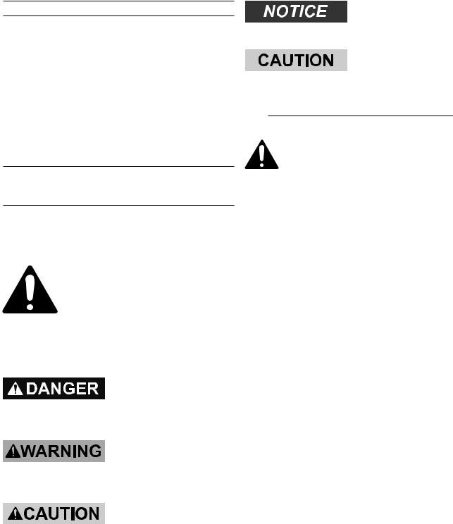
In this manual, on the labeling, and all other information provided with this product:
This is the safety alert symbol. It is used to alert you to potential personal injury hazards. Obey all safety messages that follow this symbol to avoid possible injury or death.
DANGER indicates a hazardous situation which, if not avoided, will result
in death or serious injury.
WARNING indicates a hazardous situation
which, if not avoided, could result in death or serious injury.
CAUTION, used with the safety alert
symbol, indicates a hazardous situation which, if not avoided, could result in minor or moderate injury.
NOTICE is used to address practices not
related to personal injury.
CAUTION, without the safety alert symbol, is
used to address practices not related to personal injury.
General Tool Safety Warnings
WARNING Read all safety warnings and instructions. Failure to follow the warnings and instructions may result in electric shock, fire and/or serious injury.
Save all warnings and instructions for future reference.
1.KEEP GUARDS IN PLACE and in working order.
2.REMOVE ADJUSTING KEYS AND WRENCHES. Form habit of checking to see that keys and adjusting wrenches are removed from tool before turning it on.
3.KEEP WORK AREA CLEAN. Cluttered areas and benches invite accidents.
4.DON’T USE IN DANGEROUS ENVIRONMENT. Don’t use power tools in damp or wet locations, or expose them to rain. Keep work area well lighted.
5.KEEP CHILDREN AWAY. All visitors should be kept safe distance from work area.
6.MAKE WORKSHOP KID PROOF with padlocks, master switches, or by removing starter keys.
7.DON’T FORCE TOOL. It will do the job better and safer at the rate for which it was designed.
SKU 93212 |
For technical questions, please call 1-800-444-3353. |
Page 3 |

8.USE RIGHT TOOL. Don’t force tool or attachment to do a job for which it was not designed.
RECOMMENDED MINIMUM WIRE GAUGE FOR EXTENSION CORDS
(120 VOLT)
NAMEPLATE |
EXTENSION CORD |
|||
AMPERES |
|
LENGTH |
|
|
(at full load) |
25’ |
50’ |
100’ |
150’ |
0 – 6 |
18 |
16 |
16 |
14 |
6.1 – 10 |
18 |
16 |
14 |
12 |
10.1 – 12 |
16 |
16 |
14 |
12 |
12.1 – 16 |
14 |
12 |
Do not use. |
|
TABLE A
9.USE PROPER EXTENSION CORD. Make sure your extension cord is in good condition. When using an extension cord, be sure to use one heavy enough to carry the current your product will draw. An undersized cord will cause a drop in line voltage resulting in loss of power and overheating. Table A shows the correct size to use depending on cord length and nameplate ampere rating. If in doubt, use the next heavier gauge. The smaller the gauge number, the heavier the cord.
10.WEAR PROPER APPAREL. Do not wear loose clothing, gloves, neckties, rings, bracelets, or other jewelry which may get caught in moving parts. Nonslip footwear is recommended. Wear protective hair covering to contain long hair.
11.ALWAYS USE SAFETY GLASSES. Also use face or dust mask if cutting operation is dusty. Everyday eyeglasses only have impact resistant lenses, they are NOT safety glasses.
12.SECURE WORK. Use clamps or a vise to hold work when practical. It’s safer than using your hand and it frees both hands to operate tool.
13.DON’T OVERREACH. Keep proper footing and balance at all times.
14.MAINTAIN TOOLS WITH CARE. Keep tools sharp and clean for best and safest performance. Follow instructions for lubricating and changing accessories.
15.DISCONNECT TOOLS before servicing; when changing accessories, such as blades, bits, cutters, and the like.
16.REDUCE THE RISK OF
UNINTENTIONAL STARTING. Make sure switch is in off position before plugging in.
17.USE RECOMMENDED ACCESSORIES. Consult the owner’s manual for recommended accessories. The use of improper accessories may cause risk of injury to persons.
18.NEVER STAND ON TOOL. Serious injury could occur if the tool is tipped or if the cutting tool is unintentionally contacted.
19.CHECK DAMAGED PARTS. Before further use of the tool, a guard or other part that is damaged should be carefully checked to determine that it will operate properly and perform its intended function – check for alignment of moving parts, binding of moving parts, breakage of parts, mounting, and any other conditions that may affect its operation.
A guard or other part that is damaged should be properly repaired or replaced.
20.NEVER LEAVE TOOL RUNNING
UNATTENDED. TURN POWER OFF.
Don’t leave tool until it comes to a complete stop.
Page 4 |
For technical questions, please call 1-800-444-3353. |
SKU 93212 |

Grounding Instructions
To prevent electric shock
and death from incorrect grounding wire connection
Read and follow these instructions:
110-120 V~ Grounded Tools: Tools
with Three Prong Plugs
1.In the event of a malfunction or breakdown, grounding provides a path of least resistance for electric current to reduce the risk of electric shock.
This tool is equipped with an electric cord having an equipment-grounding conductor and a grounding plug. The plug must be plugged into a matching outlet that is properly installed and grounded in accordance with all local codes and ordinances.
2.Do not modify the plug provided – if it will not fit the outlet, have the proper outlet installed by a qualified electrician.
3.Improper connection of the equipmentgrounding conductor can result in a risk of electric shock. The conductor with insulation having an outer surface that is green with or without yellow stripes is the equipment-grounding conductor. If repair or replacement of the electric cord or plug is necessary, do not connect the equipment-grounding conductor to a live terminal.
4.Check with a qualified electrician or service personnel if the grounding instructions are not completely understood, or if in doubt as to whether the tool is properly grounded.
5.Use only 3-wire extension cords that have 3-prong grounding plugs and
3-pole receptacles that accept the tool’s plug.
6.Repair or replace damaged or worn cord immediately.
125 V~ 3-Prong Plug and Outlet
(for up to 125 V~ and up to 15 A)
7.This tool is intended for use on a circuit that has an outlet that looks like the one illustrated above in 125 V~ 3-Prong Plug and Outlet. The tool has a grounding plug that looks like the plug illustrated above in 125 V~ 3-Prong Plug and Outlet.
8.The outlet must be properly installed and grounded in accordance with all codes and ordinances.
9.Do not use an adapter to connect this tool to a different outlet.
Mini Lathe Safety Warnings
1.For your own safety, Read and understand this instruction manual before operating lathe.
2.Wear ANSI-approved eye protection.
3.Do not wear gloves, necktie, or loose clothing while operating the Lathe.
4.Tie back long hair. Long hair in a ponytail needs to be secured so there is no risk of entanglement.
5.Tighten all locks before operating.
SKU 93212 |
For technical questions, please call 1-800-444-3353. |
Page 5 |
6.Do not operate with ANY guard disabled, damaged, or removed. Moving guards must move freely and close instantly.
7.Rotate workpiece by hand before applying power.
8.Rough out workpiece before installing on faceplate.
9.Do not mount split workpiece or one containing knot.
10.Use lowest speed when starting new workpiece.
11.Do not reverse motor direction while the lathe is in motion.
12.Do not clear chips by hand or when lathe is running. Use a brush to sweep chips away after the tool has come to a complete stop.
13.Select the proper tool for the job. Using the correct tool for the job produces a better finish and minimizes strain on the lathe.
14.The use of accessories or attachments not recommended by the manufacturer may result in a risk of injury to persons. When servicing, use only identical replacement parts.
15.Support pieces extending beyond the headstock so they cannot cause injury to the operator, bystanders or lathe. Turn supported long stock at slower RPM’s.
16.Use a chuck cradle or piece of plywood to protect the precision ground ways and your hands when servicing chucks.
17.Check that the workpiece, tool, tool post, chuck and saddle all have adequate clearance before starting the lathe.
18.Check that no part of the tool, tool holder, compound slide, cross slide, or
carriage will contact the chuck during operation.
19.Use the appropriate feed and speed rates for the project.
20.Allow the lathe to reach its full speed before beginning a cut.
21.Only use safety equipment that has been approved by an appropriate standards agency. Unapproved safety equipment may not provide adequate protection.
Eye protection must be ANSI-approved and breathing protection must be
NIOSH-approved for the specific hazards in the work area.
22.Industrial applications must follow OSHA guidelines.
23.Maintain labels and nameplates on the tool. These carry important safety information. If unreadable or missing, contact Harbor Freight Tools for a replacement.
24.Avoid unintentional starting. Prepare to begin work before turning on the tool.
25.People with pacemakers should consult their physician(s) before use.
Electromagnetic fields in close proximity to heart pacemaker could cause pacemaker interference or pacemaker failure.
26.WARNING: Some dust created by power sanding, sawing, grinding, drilling, and other construction activities, contains chemicals known [to the State of
California] to cause cancer, birth defects or other reproductive harm. Some examples of these chemicals are:
•Lead from lead-based paints
•Crystalline silica from bricks and cement or other masonry products
•Arsenic and chromium from chemically treated lumber
Page 6 |
For technical questions, please call 1-800-444-3353. |
SKU 93212 |

Your risk from these exposures varies, depending on how often you do this type of work. To reduce your exposure to these chemicals: work in a well ventilated area, and work with approved safety equipment, such as those dust masks that are specially designed to filter out microscopic particles. (California Health
& Safety Code § 25249.5, et seq.)
27.WARNING: Handling the cord on this product will expose you to lead, a chemical known to the State of California to cause cancer, and birth defects or other reproductive harm. Wash hands after handling. (California Health &
Safety Code § 25249.5, et seq.)
28.The warnings, precautions, and instructions discussed in this instruction manual cannot cover all possible conditions and situations that may occur. It must be understood by the operator that common sense and caution are factors which cannot be built into this product, but must be supplied by the operator.
or physical symptoms related to vibration (such as tingling, numbness, and white or blue fingers), seek medical advice as soon as possible.
2.Do not smoke during use. Nicotine reduces the blood supply to the hands and fingers, increasing the risk of vibration-related injury.
3.Wear suitable gloves to reduce the vibration effects on the user.
4.Use tools with the lowest vibration when there is a choice between different processes.
5.Include vibration-free periods each day of work.
6.When cutting do not apply too much pressure to the workpiece. Let the tool do the work.
7.To reduce vibration, maintain the tool as explained in this manual. If any abnormal vibration occurs, stop use immediately.
Vibration Safety
This tool vibrates during use. Repeated or long-term exposure to vibration may cause temporary or permanent physical injury, particularly to the hands, arms and shoulders. To reduce the risk of vibration-related injury:
1.Anyone using vibrating tools regularly or for an extended period should first be examined by a doctor and then have regular medical check-ups to ensure medical problems are not being caused or worsened from use. Pregnant women or people who have impaired blood circulation to the hand, past hand injuries, nervous system disorders, diabetes, or Raynaud’s Disease should
not use this tool. If you feel any medical
REV 10b
Save these instructions.
SKU 93212 |
For technical questions, please call 1-800-444-3353. |
Page 7 |

Specifications |
Packing List |
Motor |
|
|
|
|
|
|
|
|
|
|
|
|
120 V~ / 60 Hz / 3/4 HP |
|
||||||||||||||
|
|
|
|
|
|
|
|
|
|
|
|
|
|
|
|
|
|
|
|
|
|
|
|
|
|
|
|
|
Speed Ranges |
|
|
|
|
|
|
|
|
0 - 1100 RPM (Low) |
|
||||||||||||||||||
|
|
|
|
|
|
|
0 - 2500 RPM (High) |
|
||||||||||||||||||||
|
|
|
|
|
|
|
|
|
|
|
|
|
|
|
|
|
||||||||||||
Fuse Type |
|
|
|
|
|
|
|
|
|
|
|
|
Fast Acting 4 amp mini |
|
||||||||||||||
|
|
|
|
|
|
|
|
|
|
|
|
glass (F4AL250VP) |
|
|||||||||||||||
|
|
|
|
|
|
|
|
|
|
|
|
|
|
|
|
|
||||||||||||
|
|
|
|
|
|
|
|
|
|
|
|
|
|
|
|
Lx136 |
|
|
|
|
|
|||||||
Belt |
|
|
|
|
|
|
|
|
|
|
|
|
Pitch: 1.5mm |
|
|
|
|
|
||||||||||
|
|
|
|
|
|
|
|
|
|
|
|
|
|
|
|
Teeth: 70 |
|
|
|
|
|
|||||||
Drive |
|
|
|
|
|
|
|
|
|
|
|
|
Gear and Belt |
|
|
|
|
|
||||||||||
Swing Over Bed |
|
|
|
|
|
|
|
7” |
|
|
|
|
|
|||||||||||||||
Dist. Between Centers |
|
|
10” |
|
|
|
|
|
||||||||||||||||||||
Swing Over Cross Slide |
|
|
2-1/8” |
|
|
|
|
|
||||||||||||||||||||
Swing Over Saddle |
|
|
|
|
|
|
|
4-1/2” |
|
|
|
|
|
|||||||||||||||
Swing Over Gap |
|
|
|
|
|
|
|
7” |
|
|
|
|
|
|||||||||||||||
Max. Tool Bit Size |
|
|
|
|
|
|
|
5/16” |
|
|
|
|
|
|||||||||||||||
Compound Travel |
|
|
|
|
|
|
|
2-3/4” |
|
|
|
|
|
|||||||||||||||
Carriage Travel |
|
|
|
|
|
|
|
6-1/2” |
|
|
|
|
|
|||||||||||||||
Cross Slide Travel |
|
|
|
|
|
|
|
2-3/4” |
|
|
|
|
|
|||||||||||||||
Work Tolerance |
|
|
|
|
|
|
|
0.005” |
|
|
|
|
|
|||||||||||||||
Bed Dimensions |
|
|
|
|
|
|
|
15-7/8” L x 3-1/4” W |
|
|||||||||||||||||||
Tailstock Taper |
|
|
|
|
|
|
|
MT#2 |
|
|
|
|
|
|||||||||||||||
Threads |
|
|
|
|
|
|
|
|
|
|
|
|
18 threads from 12 - 52 |
|
||||||||||||||
|
|
|
|
|
|
|
|
|
|
|
|
TPI |
|
|
|
|
|
|||||||||||
|
|
|
|
|
|
|
|
|
|
|
|
|
|
|
|
|
|
|
|
|
||||||||
Through Chuck Capacity |
|
|
5/8” |
|
|
|
|
|
||||||||||||||||||||
|
|
|
|
|
|
|
|
|
|
|
|
|
|
|
|
|
|
|
|
|
|
|
|
|
|
|
|
|
Chuck Dia. |
|
|
|
|
|
Internal Jaws |
|
|
|
External |
||||||||||||||||||
(mm) |
|
|
|
|
|
|
|
|
Jaws |
|||||||||||||||||||
|
|
|
|
|
|
|
|
|
|
|
|
|
|
|
|
|
|
|
|
|||||||||
80 |
|
|
|
|
|
|
A - A1 |
|
|
|
B - B1 |
|
|
|
C - C1 |
|||||||||||||
|
|
|
5/64” - 1-1/8” |
1” - 2-3/4” |
7/8” - 2-1/2” |
|||||||||||||||||||||||
|
|
|
|
|
||||||||||||||||||||||||
|
|
|
|
|
|
|
|
|
|
|
|
|
|
|
|
|
|
|
|
|
|
|
|
|
||||
|
|
|
|
|
|
|
|
|
|
|
|
|
|
|
|
|
|
|
|
|
|
|
|
|
C1 |
|
|
|
|
A |
B |
|
|
|
|
A1 |
|
B1 |
|
|
|
|
C |
|
|
|
|
||||||||||
|
|
|
|
|
|
|
|
|
|
|
|
|
|
|
|
|
|
|
|
|
|
|
|
|
|
|
|
|
|
|
|
|
|
|
|
|
|
|
|
|
|
|
|
|
|
|
|
|
|
|
|
|
|
|
|
|
|
|
|
|
|
|
|
|
|
|
|
|
|
|
|
|
|
|
|
|
|
|
|
|
|
|
|
|
|
|
|
|
|
|
|
|
|
|
|
|
|
|
|
|
|
|
|
|
|
|
|
|
|
|
|
|
|
|
|
|
Description |
Qty |
Part |
|
#(s) |
||
|
|
|
|
1 |
Main unit |
1 |
|
2 |
External Chuck Jaw Set |
3 jaws |
166 |
3 |
Chip Tray |
1 |
126 |
4 |
Chuck Key |
1 |
167 |
5 |
5 A Fuse |
1 |
314 |
6 |
Gear: 30, 35, 40, 40, 45, |
10 |
157- |
|
50, 55, 57, 60, 65 T |
gears |
165 |
7 |
Spanner Wrench: 8-10, |
2 |
312, |
|
14-17 |
wrenches |
313 |
8 |
Hex Key Wrench Set: 3, |
4 |
311 |
|
4, 5, 6 |
wrenches |
|
9 |
Oil can |
1 |
310 |
10 |
MT:2 Live Center |
1 |
143 |
11 |
Rubber Foot |
4 |
125 |
12 |
Rubber Foot Mounting |
4 |
67 |
|
Screw |
|
|
13 |
Knob |
2 |
85 |
14 |
Manual |
1 |
317 |
Shipping Bolt Locations
To remove the lathe from the packing crate, remove both bolts on the crate bottom as shown above.
Unpacking
When unpacking, make sure that the item is intact and undamaged. If any parts are missing or broken, please call Harbor Freight Tools at 1-800-444-3353 as soon as possible.
Many components need to be installed before use. It is ESSENTIAL that both guards (found in separate boxes within the main box) are installed before connecting power.
Note: Wipe off protective grease from the lathe before using.
REV 10b, 10e
Page 8 |
For technical questions, please call 1-800-444-3353. |
SKU 93212 |

General Mini Lathe Components
Note: Refer to the parts list and diagram at the end of this manual for complete part number listings and locations. See the following page for a description of the major components.
Part |
|
Description |
|
|
1 |
Bed Way |
|
|
|
2 |
Chuck |
|
|
|
33 |
H/L Speed Gear Shift Lever |
|
||
35 |
Feed Direction Selector |
|
|
|
53 |
Gear Drive Cover |
|
|
|
79 |
Automatic Feed Handle |
|
|
|
84a |
Tailstock Quill Control Wheel |
|
||
84b |
Feed Control Wheel |
|
|
|
86a |
Cross Slide Crank |
|
|
|
86b |
Compound Rest Crank |
|
|
|
100 |
Cross Slide |
|
|
|
105/108 |
Compound Rest (A and B) |
|
|
|
112 |
Tool Post |
|
|
|
124 |
Power Cord |
|
|
|
|
181 |
179 |
180 |
2 |
178
Part |
|
|
Description |
|||
126 |
|
Chip Tray |
|
|
|
|
129 |
|
Lead Screw |
|
|
||
138 |
|
Tailstock |
|
|
|
|
143 |
|
Live Center |
|
|
||
146 |
|
Tailstock Quill Fix Holder |
|
|||
151 |
|
Motor Cover |
|
|
||
153 |
|
Rear Splash Guard |
|
|||
178 |
|
Power Switch |
|
|
||
179 |
|
Fuse Holder |
|
|
||
180 |
|
Speed Control Knob |
|
|||
181 |
|
Forward-Off-Reverse Switch |
||||
268 |
|
Tailstock Set Screw |
|
|||
302 |
|
Thread Dial Indicator |
|
|||
112 |
105 |
143 |
146 |
138 |
84(a) |
|
268
86(b)
1 |
84(b) |
86(a) |
100 |
79 |
302 |
129 |
|
|
|
|
|
|
|
53 |
35 |
153 
126 |
Figure 1 |
33 |
151 |
124 |
REV 10b |
|
|
|
|
|
|
|
|
|
SKU 93212 |
For technical questions, please call 1-800-444-3353. |
Page 9 |
||
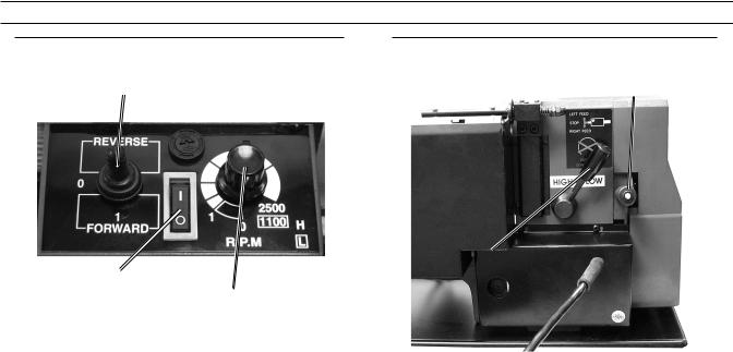
Power Controls overview
Controls on the Front of the Lathe |
Controls on the Back of the Lathe |
Forward-OFF-Reverse Switch (181)
Power Switch (178)
Figure 2 |
Speed Control Knob (180) |
|
Power Switch (178)
Turns on and off power to the motor.
When the Power Switch is lit, the motor is on.
Forward-OFF-Reverse Switch (181)
Changes the Spindle (3) (Chuck (2)) rotation from Forward (clockwise), to OFF (no rotation), to Reverse
(counterclockwise).
DO NOT change the Forward-OFF- Reverse Switch direction while the lathe is running.
Speed Control Knob (180)
Adjusts the Spindle (3) speed from 0 to
2500 RPMs.
Check that this knob is at 0 before turning on the Lathe.
Note: The Speed Control Knob (180) is dependant on the H/L Gear Shift Lever
(33). When the H/L Gear Shift Lever is in the Low setting, the Speed Control Knob runs from 0 to 1100 RPM. When the H/L Gear Shift Lever is in the High setting, the Speed Control Knob runs from 0 to
Feed Direction Selector (35)
H/L Gear Shift Lever (33)
Figure 3
Feed Direction Selector (35)
Changes the Lead Screw (129) rotation from Forward (toward the Chuck) to Neutral (no rotation), to Reverse (away from the Chuck).
DO NOT Change the Feed Direction Selector while the Lathe is running.
H/L Gear Shift Lever (33)
Changes the spindle speed range from High (0 - 2500 RPM) to Low (0-1100
RPM).
DO NOT adjust the H/L Gear Shift Lever while the Lathe is running.
2500 RPM. |
|
REV 10b |
|
|
|
Page 10 |
For technical questions, please call 1-800-444-3353. |
SKU 93212 |
Lathe components overview
Following are brief descriptions of major components of the Mini Lathe.
Bed Way (1) - The Bed Way is the base of the work area under the Chuck and
Tailstock. It is where the Tailstock and Compound Rest are attached and what they slide along.
Chuck (2) - The Chuck holds the three Jaws
(two sets included) which clamp the work piece in place.
Compound Rest (105/108) - The Compound
Rest and Compound Slide (100) work together to adjust the position of the Cutting Tool to the desired location.
Jaws (166 & 168) - The Jaws fit into the
Chuck (2) and hold the workpiece in place. There are a set of internal Jaws
(168), which fit inside the workpiece and External Jaws (166) which fit on the outside of the workpiece.
Lead Screw (129) - The Lead Screw controls automatic feeding. In thread cutting or when you want to cut into the workpiece automatically, you engage the Lead Screw with the Feeding Direction Selector (35) and use the Automatic
Feed Handle (79). Keep track of the cut with the Thread Dial Indicator (302).
Live Center (143) - The Live Center fits into the Tailstock Quill (142) on the Tailstock (138) and helps to hold the end of the workpiece that is opposite from the
Chuck (2). A live center spins with the workpiece and chuck, while a dead center (sold separately) does not spin.
Tailstock (138) - The Tailstock holds the Tailstock Quill (142) which is used to hold various tools (sold separately) or a Live Center (143).
Thread Indicator Dial (302) - The Threading Dial is used to measure the number of rotations of the Lead Screw when thread cutting. It eliminates the need to reverse the lathe and return the carriage to the starting point each time a successive threading cut is taken. You must adjust the Threading Dial so that it engages the Lead Screw (129) in order for it to function.
Threading Gears (45,50, 59, 157-165) - The
Threading Gears are positioned under the Gear Drive Cover (53) on the far left side of the Lathe. They are used in various configurations for thread cutting.
Tool Post (112) - The Tool Post sits on the top of the Compound Rest (105/108) and is used to hold various cutting tools by clamping them in place with Tool Post Bolts (110).
REV 10b |
|
|
SKU 93212 |
For technical questions, please call 1-800-444-3353. |
Page 11 |
Assembly Instructions
Note: For additional information regarding the parts listed in the following pages, refer to the Assembly Diagram near the end of this manual.
1. WARNING! Make sure the Power
Switch of the tool is in its “OFF” position and that the tool is unplugged from
its electrical outlet before making any adjustments to the tool.
2.Clean off the protective grease on the
Mini Lathe.
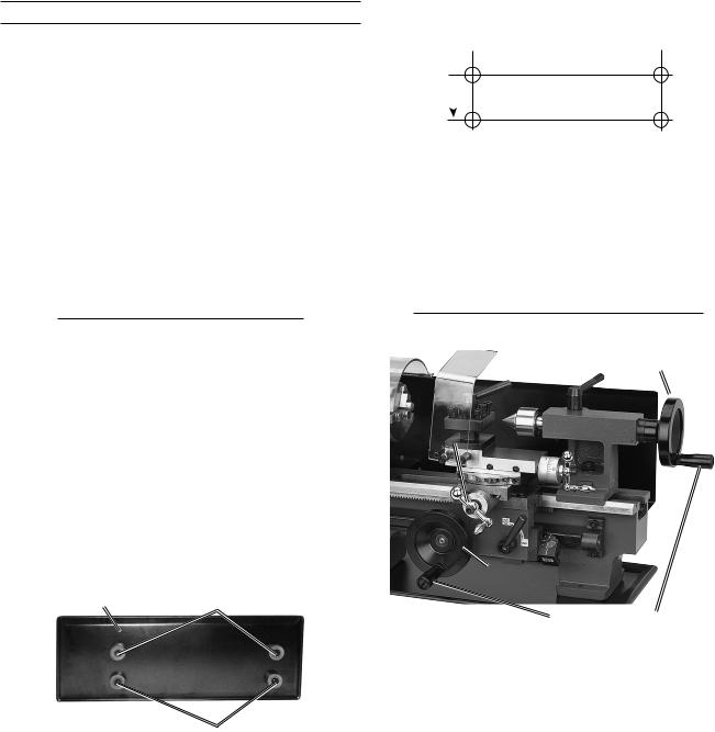
To Mount the Lathe to a Workbench:
Drill holes for permanent mounting:  14-7/8”
2-7/8”
Figure 5
Unthread the Bolts (67) from the bottom of the unit. Measure and drill holes in the workbench. Use appropriate length M6-1 bolts and washers (sold separately) to secure the Lathe and Chip Tray to the workbench.
Attaching Rubber Feet or Installing to Workbench
Note: Mount or place the Lathe on a sturdy workbench or table, with good lighting, at a height that allows you to comfortably work without back strain.
The Lathe can be mounted permanently to a workbench or used with it’s included
Rubber Feet (125) on a tabletop.
To Attach the Rubber Feet:
Chip Tray (126) |
Bolts (67) |
 Rubber Feet (125)
Figure 4 |
Bolts (67) |
To attach the Rubber Feet to the bottom of the Lathe, unthread the Bolts (67) from the bottom of the Chip Tray (126).
Slide the Rubber Feet onto the Bolts and re-thread them into the bottom of the Lathe through the Chip Tray holes.
Tighten securely.
Installing Handwheel Handles
Tailstock Quill Control Wheel (84a)
Cross Slide
Crank (86a)
Feed Control Wheel (84b)
Figure 6 |
Handwheel Handles |
1.To install the Handwheel Handles on the
Tailstock Quill Control Wheel (84a) and the Feed Control Wheel (84b), use a flathead screwdriver and a 14mm open end wrench to thread the handles onto the wheels.
2.For packaging purposes, the Cross Slide
Crank (86a) is shipped from the factory facing backwards. Adjust the Cross Slide
Crank (86a) to face forward using a 5mm
Hex Wrench (part of 311) to unthread the
Cap Screw (52) and turn the Cross Slide Crank around. Tighten the Cap Screw securely.
REV 10b
Page 12 |
For technical questions, please call 1-800-444-3353. |
SKU 93212 |
 Loading...