


PCA 300/PCA 301
Series
Panel-mounted,
Microprocessor-based
Chlorine Analyzers
Instruction Manual

Dear Customer,
Thank you for choosing a Hanna Product.
This instruction manual has been written for the following products:
PCA 300 Free Chlorine Analyzer with features such as alarm functions, user-se- lectable sampling periods, LED warning indications, recorder outputs, RS232 port and a Nema 4X, 12 and 13 enclosure.
PCA 301 Total Chlorine Analyzer with features such as alarm functions, userselectable sampling periods, LED warning indications, recorder outputs, RS232 port and a Nema 4X, 12 and 13 enclosure.
PCA 300A Same as PCA 300 except for the RS232 port which is not supplied. PCA 301A Same as PCA 301 except for the RS232 port which is not supplied.
PCA 300AC This OEM version is exactly the same as PCA 300 except for the RS232 port and the enclosure.
PCA 301AC This OEM version is exactly the same as PCA 301 except for the RS232 port and the enclosure.
Please read this instruction manual carefully before using the instrument. It will provide you with the necessary information for the correct use of the instrument, as well as a more precise idea of its versatility.
These instruments are in compliance with 
 directives. The PCA 300 and PCA 301 are also registered by Underwriters Laboratories Inc. (UL approved).
TABLE OF CONTENTS
PRELIMINARY EXAMINATION . . . . . . . . . . . . 4
GENERAL DESCRIPTION. . . . . . . . . . . . . . . . 5
MECHANICAL DIMENSIONS . . . . . . . . . . . . 6
FUNCTIONAL DESCRIPTION . . . . . . . . . . . . 7
LED DISPLAY, INDICATORS AND KEYBOARD . 8
SPECIFICATIONS . . . . . . . . . . . . . . . . . . . . 10
OPERATING DESCRIPTION . . . . . . . . . . . . . 12
Method of analysis . . . . . . . . . . . . . . . . 13
INITIAL PREPARATION AND INSTALLATION . 14
Installation Personnel . . . . . . . . . . . . . . 14
Location of the Instrument . . . . . . . . . . . 14
Hydraulic Connections . . . . . . . . . . . . . 14
Installing the Input Filter . . . . . . . . . . . . 16
Installing the Pump Tubes . . . . . . . . . . . 16
Electrical Connections . . . . . . . . . . . . . 18
2
START-UP . . . . . . . . . . . . . . . . . . . . . . . . . . . 22
Instrument Power On . . . . . . . . . . . . . . . . 22
Display Brightness . . . . . . . . . . . . . . . . . . 22
Minimum and Maximum Concentration . . . 23
Sampling Rate . . . . . . . . . . . . . . . . . . . . 24
Priming the Reagent System . . . . . . . . . . . 24
ANALYZER PROGRAMMING . . . . . . . . . . . . . 26
Proportional Dosing . . . . . . . . . . . . . . . . 26
Concentration Setpoint Alarm Setting . . . . . 28
Recorder Output Span Setting . . . . . . . . . . 30
Standby Mode . . . . . . . . . . . . . . . . . . . . 32
Recorder Output Calibration . . . . . . . . . . . 33
Recorder Output Limits Check . . . . . . . . . . 40
Adjusting the Light Source . . . . . . . . . . . . 42
MAINTENANCE . . . . . . . . . . . . . . . . . . . . . . 44
Calibration Requirement. . . . . . . . . . . . . . 44
Hydraulic System . . . . . . . . . . . . . . . . . . . 44
Reagents Supply . . . . . . . . . . . . . . . . . . . 44
Changing Peristaltic Pump Tubing . . . . . . . 46
Tubing Replacement . . . . . . . . . . . . . . . . 47
“Y” Strainer Cleaning . . . . . . . . . . . . . . . 47
Cleaning Measurement Cell . . . . . . . . . . . 47
Relay Test . . . . . . . . . . . . . . . . . . . . . . . . 48
Calibration Procedure . . . . . . . . . . . . . . . 48
ERROR CODES . . . . . . . . . . . . . . . . . . . . . . . 50
OPERATIONAL & DIAGNOSTIC CODES . . . . . 53
INTERFACE WITH PC . . . . . . . . . . . . . . . . . . . 55
ACCESSORIES . . . . . . . . . . . . . . . . . . . . . . . 56
WARRANTY . . . . . . . . . . . . . . . . . . . . . . . . . 57
CE DECLARATION OF CONFORMITY . . . . . . . 59
© 1997 Hanna Instruments
All rights are reserved. Reproduction in whole or in part is prohibited without the written consent of the copyright owner, Hanna Instruments Inc., 584 Park East Drive, Woonsocket, Rhode Island, 02895 , USA.
3

PRELIMINARY EXAMINATION
Remove the analyzer from the packing material and examine it carefully to make sure that no damage has occurred during shipping. If there is any noticeable damage, notify your Dealer immediately.
Each analyzer is supplied complete with:
•2 reagent bottles (1 indicator and 1 buffer solution) (PCA 300 and PCA 301 only)
•2 reagent bottle caps (PCA 300 and PCA 301 only)
•1 DPD compound powder (PCA 300 and PCA 301 only)
•tubing
•mounting brackets
Note Save all packing materials until you are sure that the instrument functions correctly. Any damaged or defective items must be returned in their original packing materials together with the supplied accessories.
WARNING The PCA300 and PCA 301 series of Chlorine Analyzers are not designed for use with samples that are inflammable or explosive in nature. If any sample solution other than water is used with these products, test the sample/product compatibility to assure user safety and proper product performance.
Safety Precautions Please take the time to read the safety precautions carefully wherever they appear in this manual. They are provided to prevent personal injury and damage to the instrument. This safety information applies to the operators and service personnel and the following two captions are used:
CAUTION: identifies conditions or practices that could result in damage to the instrument or persons;
WARNING: identifies conditions or practices that could result in personal injury or loss of life.
Note Because of the inherent dangers in handling chemical samples, standards and reagents, HANNA Instruments strongly recommends the users of this product review the Material Safety Data Sheets and become familiar with safe handling procedures and proper usage prior to handling any chemicals.
4

GENERAL DESCRIPTION
The Hanna PCA 300 and PCA 301 series of Chlorine Analyzers are microprocessor-controlled, process analyzers which continuously monitor a sample stream for Chlorine content.
The PCA 300 series monitor Free Chlorine and the PCA 301 series Total Chlorine in the 0 to 5 mg/L (ppm) range.
In the DPD Colorimetric method, N, N-Diethyl-p-phenylene- diamine indicator and a buffer are mixed with the sample. The resulting chemical reaction causes a magenta color to form. The color intensity is proportional to the concentration of Chlorine. The color intensity is measured photometrically (with a light beam and a photodetector) and converted to Chlorine concentration, in mg/L, which is displayed on the front panel, four-digit, LED display.
Indicator and buffer reagent bottles are placed directly into the instrument case. With a sampling period of 5 minutes, reagents need to be replenished about once a month. The reagent bottles are easily visible through the transparent window to allow the operator to check the reagent levels.
The cases of PCA 300 and PCA 301 meet NEMA 4X, 12 and 13 standards. Molded fiberglass polyester has outstanding chemical and temperature resistance.
External mounting feet provide wall mounting capability and a seamless gasket assures a watertight and dust-tight seal.
The electrical and hydraulic connections (except for PCA 300AC and PCA 301AC OEM models) are made through the side of the enclosure.
The front cover is secured with two lockable latches.
5
Two selectable chlorine level setpoints can be set by the operator: a proportional dosing setpoint and an alarm setpoint. Both setpoints control a SPDT relay.
The proportional dosing setpoint analyzers is user-selectable with a delta from 0.1 to 2.0 mg/L (ppm).
The alarm level can be set by the user to be an “activate- if-lower-than” setpoint or an “activate-if-greater-than” setpoint.
A system alarm feature provides relay activation to signal need for operator intervention.
The PCA 300 and PCA 301 analyzers can supply data to an external computer through an RS232C output connection.
Voltage output levels of 0-10mV, 0-100mV, 0-1V or a current output of 4-20 mA are selectable to drive an external device such as a chart recorder or an external regulator. Recorder span minimum and maximum values in mg/L are programmable by the operator through the keyboard.
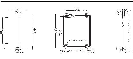
MECHANICAL DIMENSIONS *
Note The enclosure is not supplied with PCA 300AC or
PCA 301AC
* Wall Mount Dimensions in mm & inches
6
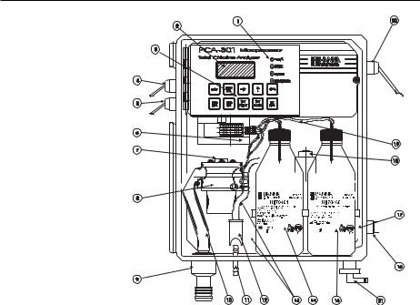
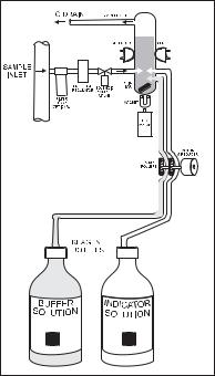
FUNCTIONAL DESCRIPTION
|
|
|
|
|
|
|
|
|
|
|
|
|
|
|
|
|
|
|
|
|
|
|
|
|
|
|
|
|
|
|
|
|
|
|
|
|
|
|
|
|
|
|
|
|
|
|
|
|
|
|
|
|
|
|
|
|
|
|
|
|
|
|
|
|
|
|
|
|
|
|
|
|
|
|
|
|
|
|
|
|
|
|
|
|
|
|
|
|
|
|
|
|
|
|
|
|
|
1. |
Alarms Indicators |
11. |
Drain Port of Measuring Cell |
||||||||||
2. |
LED Display |
12. |
Drain Port Valve |
||||||||||
3. |
Keyboard |
13. |
Sample Tubing |
||||||||||
4. |
Alarms Output |
14. |
Buffer Bottle |
||||||||||
5. |
Recorder Output |
15. |
Indicator Bottle |
||||||||||
6. |
Peristaltic Pump |
16. |
Sample Port |
||||||||||
7. |
Access Point to Cell |
17. |
Incoming Pressure Regulator |
||||||||||
8. |
Measuring Cell |
18. |
Electrovalve |
||||||||||
9. |
Output Port |
19. |
Reagent Tubing |
||||||||||
10. |
Drain Tube |
20. |
Line Input |
||||||||||
|
|
21. |
Pressure Regulator Output Port |
||||||||||
 Unplug the meter before any electrical connection.
7
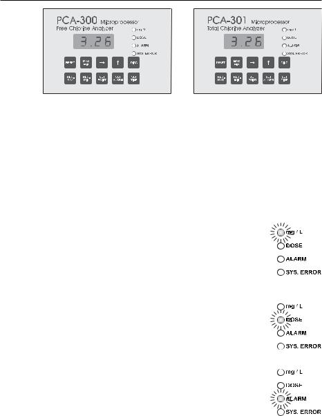
LED DISPLAY, INDICATORS AND KEYBOARD
DIGITAL DISPLAY
The digital readout will indicate the Chlorine concentration of the last sample measured in milligrams per liter (mg/L) during normal operation.
Only when a key is pressed to execute some other function, will the concentration reading be interrupted. In this case, the Chlorine mg/L indicator is turned off.
If the Chlorine concentration is above 5 mg/L, the display will blink.
mg/L CHLORINE INDICATOR
During normal operation, this green indicator will be on continuously, indicating that the LED is displaying Chlorine concentration. During the diagnostic or other modes this indicator will be off.
DOSE INDICATOR
When proportional dosing is active, the dose LED will be on and the corresponding relay closes. This LED turns off automatically when the proportional dosing stops.
ALARM INDICATOR
This LED will be on when the programmed alarm setpoints are exceeded. The alarm LED turns off automatically when the alarm condition disappears.
8
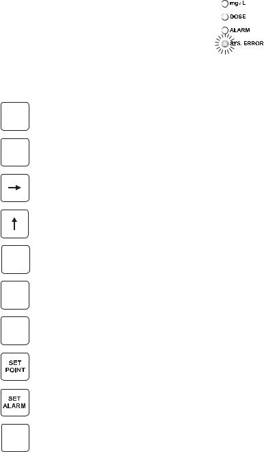
SYSTEM ERROR INDICATOR
This LED is lit when a system error has occurred. If the situation persists for more than
a few samples, the operator should notify maintenance personnel for investigation of the problem. When the meter is in system error mode, the user can directly access the diag-
nostic code that indicates the source of error. The analyzer continues to perform the sampling operations during an alarm condition.
KEYBOARD DESCRIPTION
RESET
MAX
MIN
DIAG
REC.
MAX
REC.
MIN
SET
TIME
The Reset key clears system alarm and restarts the analyzer.
The Max/Min key alternately displays maximum and minimum Chlorine concentration levels since last reset.
The RIGHT arrow key is used to shift digit position within a displayed number.
The UP arrow key is used to scroll up a displayed digit: 0, 1, 2 ..... 9, 0, 1, 2, etc.
The DIAG key is used to select programming and self-diag- nostic modes.
The Rec.Max key is used to enter and recall maximum value of the recorder output in mg/L.
The Rec.Min key is used to enter and recall minimum value of recorder output in mg/L.
The Set Point key is used to enter and recall concentration setpoint.
The Set Alarm key is used to enter and recall concentration alarm setpoint.
The Set Time key is used to enter and recall time intervals between two consecutive samples.
9

SPECIFICATIONS
|
PCA 300 |
PCA 301 |
|
|
|
Range |
0.00 to 5.00 mg/L |
0.00 to 5.00 mg/L |
|
Free Cl2 |
Total Residual Cl2 |
|
|
|
Resolution |
0.01 mg/L |
|
|
|
|
Accuracy |
±8% of reading or ±0.05 mg/L |
|
|
whichever is greater |
|
|
|
|
Typical EMC |
±0.05 mg/L |
|
Deviation |
|
|
|
|
|
Minimum |
0.05 mg/L |
|
detectable level |
|
|
|
|
|
Repeatability |
±0.05 mg/L |
|
Response time Related to the sampling time selected. Typical for a full scale step change and 5 minutes between two consecutive samples: one sampling cycle for 90% response and two sampling cycles for 100% response
Sampling rate Adjustable from 3 to 102 minutes
Sample inlet 0.07 bar (1psig) min., 4 bar (57.2 psig) pressure max. An internal regulator reduces pressure from 4 bar (57.2 psig) to
1 bar (14.3 psig)
Sample flow Flow rate of 300 mL/min is recomrange mended. Minimum and maximum allowed are 100 mL/min and
500 mL/min, respectively
Sample 5 to 40°C (41 to 104°F) temperature range
Interferences Oxidizing agents such as: Iodine, Bromine, Ozone, Chlorine Dioxide, Permanganate, Hexavalent Chromium. Hardness must not exceed 1000 mg/L as CaCO3. Alkalinity must not exceed
10
|
400mg/L for Free Chlorine analysis (PCA |
|
300) or 700mg/L for Total Chlorine |
|
analysis (PCA 301) |
|
|
Operating |
5 to 40°C (41 to 104°F) |
temperature range
Recorder output |
Selectable 0-10mV, 0-100mV, 0-1V or |
|
4-20 mA. Output span is settable |
|
anywhere in the 0-5 mg/L range |
|
|
Dosage |
Proportional on one point with a delta |
|
adjustable at 0.1, 0.2, 0.3, 0.4, 0.5, |
|
0.6, 0.7, 0.8, 0.9, 1.0, 1.5, 2.0 mg/L, |
|
equipped with a SPDT relay with |
|
contacts rated for resistive load: 5 A at |
|
250VAC or 5 A at 30VDC; inductive |
|
load: 2 A at 250VAC or 3 A at 30VDC. |
|
|
Alarms |
One sample concentration alarm |
|
adjustable as minimum or maximum |
|
acceptable value, equipped with a |
|
SPDT relay with contacts rated for |
|
resistive load: 5 A at 250VAC or 5 A at |
|
30VDC; inductive load: 2 A at 250VAC |
|
or 3 A at 30VDC. |
|
One system error alarm |
|
|
Power |
20VA at 115VAC/230VAC; |
requirements |
50/60 Hz |
|
|
Sample inlet |
12 mm (1/2”) male NPT fitting |
connection |
|
|
|
Drain connection 10 mm (3/8”) barb fitting |
|
|
|
Case |
NEMA-4X molded fiberglass polyester |
|
instrument enclosure with transparent |
|
GE Lexan window (not PCA 300AC and |
|
PCA 301AC) |
|
|
Dimensions |
318 x 267 x 159 mm |
|
(12.5 x 10.5 x 6.25") |
|
|
Weight |
5 Kg (11 lb.) |
|
|
11

OPERATING DESCRIPTION
Referring to the drawing on page 7 and the Fluidic Diagram on page 13, the Sample Line is connected to the instrument at the Sample Port (#16); an internal Regulator (#17) reduces the inlet pressure from a maximum of 4 bar (57.2 psig) down to 1 bar (14.3 psig); from the Regulator a nylon tube is connected to the input of the Electrovalve (#18). The output of the valve goes to the Drain Port (#11 in PCA 300 and PCA 301 only) and then to the Measuring Cell (#8). An optional Filter can be installed to the sample port if the stream is excessively turbid.
The sample coming from the line normally flows through the Measuring Cell. It goes out from the Measuring Cell through the Drain Tube (#10) and the Output Port (#9).
The Measuring Cell is accessible from the port placed on the top (#7) for speedy cleaning and maintenance.
During the time between two successive sampling, the analyzer solenoid input valve is open to allow sample flow to flush the colorimeter cell. Every 3 to 102 minutes (user selectable), the valve closes stopping the sample flow and leaving the sample cell full of fresh sample. Cell volume is controlled by an overflow gateway.
As the sample inlet valve closes, a series of measurements (with LED on and off) of the unreacted sample is taken to determine an average Blank level prior to reagent addition. The measurement of sample blank signal permits compensation for any turbidity or natural color, and provides the zero reference point for the measurement.
The two channel Peristaltic Pump (#6) starts rotating causing a precise quantity of buffer and indicator (#14 and #15) to enter the colorimeter sample cell where a magnetically coupled stirrer mixes the reagents with the sample.
After a delay for the development of color, a series of measurements (with LED on and off) are taken (Sample level) to determine an average Chlorine concentration measurement. The reacted sample signal is then measured and displayed.
This sequence is repeated every 3 to 102 minutes (user-se- lectable).
12
Fluid Diagram of the Analyzers
METHOD OF ANALYSIS
Free available Chlorine (monitored by the PCA300 series) oxidizes the DPD indicator reagent at a pH between 5.5 and 6.0 to form a magenta-colored compound. The intensity of the resulting color is proportional to the concentration of Chlorine in the sample. The purpose of the buffer solution is to maintain the proper pH.
To measure Total Residual Chlorine (Free available Chlorine plus combined Chloramines) the PCA301 series adds Potassium Iodide. The Chloramines in the sample cause iodide ions to become iodine which then act with free Chlorine to oxidize the DPD indicator. After the chemical reaction is complete, the optical signal at 555 nm is compared to the signal measured through the sample (before the reagents were added). From these measurements Chlorine concentration is calculated.
13

INITIAL PREPARATION AND INSTALLATION
INSTALLATION PERSONNEL
Installation of the PCA 300 and PCA 301 family of Chlorine Analyzers should be undertaken by persons with technical knowledge of the dangers associated with chemical exposure and electrical shock.
Hanna Instruments assumes persons performing the installation tasks are aware of the appropriate safety procedures.
Review the Material Safety Data Sheets (MSDS) before handling the supplied chemical reagents.
LOCATION OF THE INSTRUMENT Analyzer Location
Locate the analyzer as close as is reasonably possible to the point where the sample is withdrawn from the product stream (referred to as the “sampling point”). This practice will minimize the amount of time it takes for the sample to flow to the analyzer from the sampling point. The result is improved response time of the analyzer to changes in Chlorine contents.
The instrument should be mounted indoors, out of direct sunlight. Instrument operating temperature is 5 to 40°C (41 to 104°F).
Sampling Point Location
Locate the sampling point to obtain a truly representative sample from the product stream. For example, be sure the sampling point is well downstream from a Chlorine feed. This assures that adequate mixing and reaction of the Chlorine before a sample is extracted.
HYDRAULIC CONNECTIONS
Note Hydraulic connections should be installed only by qualified personnel to assure conformity to applicable plumbing codes.
Sample Line Installation
Sample lines of 3 mm (1/8") ID tubing are recommended to keep the sample volume in the tubing to a minimum. This reduces lag time for the sample flow from the sampling point to the instrument. In any case note that sample should reach the measuring cell in less then 100 seconds.
14
Direct routing of sample lines is also recommended.
If the large process pipes are horizontal, taps should be inserted vertically in the middle of the pipe to avoid pulling sediment from the bottom or air bubbles from the top of the pipe into the sample line.
A 1/2” BSP sample input fitting allows direct connection to the optional input filter.
Sample line pressure should be between 0.07 and 4 bar (1 and 57.2 psig) with an ideal pressure of 0.7 bar (10 psig).
Drain Line Installation
The drain hose fitting is a 20 mm (3/4”) hose barb on the bottom of the instrument enclosure. An air gap between the end of the drain hose and the drain is recommended to prevent any back flow into the instrument in the event of drain blockage.
15
Return Line Installation
The return hose fitting is a 12 mm (1/2”) hose barb on the bottom of the regulator output port and should always be connected even when pressure is below 1 bar.
INSTALLING THE INPUT FILTER
In order to ensure maximum accuracy of measurements, it is recommended to have always clear sample, with suspended particles smaller than 0.5 µm. This can be achieved by installing two filters before the sample input.
The type of filters depends on the quality of the water: the first filter should have 50-100 µm pore size, whereas in any case the second filter, the one closer to the analyzer, has to be 0.5 µm.
For correct installing procedure and maintenance, see the instructions of filters.
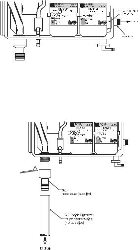
INSTALLING THE PUMP TUBES
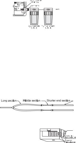
Locate the analyzer reagent tubes in the accessory kit. Each tube is composed of three sections. The sections are joined together by plastic connectors with plastic collars at the ends of the center section.
Locate the peristaltic pump.
Feed one tube from the shorter end section behind the pump rollers from the right side of the pump. Seat the plastic collar at the right end of the center sec- 


tion of tubing into the lower right indentation hole of the pump face.
16

Grasp the other plastic collar and pull, stretching the center section, and place the grommet in the lower left indentation hole.
Repeat this process with the second pump tube, placing it in the upper indentation holes.
Separate reagent caps are provided in the accessory kit. Put the supplied caps onto each reagent bottle prior to installing them. Place the indicator bottle (HI 70450 for PCA 300 and HI 70460 for PCA 301) on the right and the buffer bottle (HI 70451 for PCA 300 and HI 70461 for PCA 301) on the left.
Note Add the content of 5 HI 70452 sachets, DPD Compound, to the Indicator Solution prior to installing it.
Connect the longer tube ends on the left side of the pump to the reagent bottle cap insert fitting.
Connect the short ends on the right side of the pump to the measuring cell reagent input port through the "Y" connector.
17
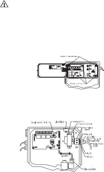
ELECTRICAL CONNECTIONS
A power cable (3 mt.) is provided with your analyzer. However, if access to the terminal block is required, see below.
Warning Electrical connections should be installed only by qualified personnel to assure conformity to applicable electrical codes.
Unplug the meter before any electrical connection.
Power
Power connections are made at a terminal block located in the center of the electrical compartment to the right of the fuses.
Hard wiring with 13 mm (½") conduit is recommended and usually required by most municipal electrical codes.
Warning Before connecting the instrument to the line:
1)Check the sticker near the fuses for proper voltage.
2)Be sure the power cord is not connected to the line.
3) Open front panel.
4)Remove the cover screws (Allen head).
5)Do not remove peristaltic pump or motor.
6)Unplug all alarms and recorder jacks.
Feed the power cord through the watertight grommet and tighten the grommet nut. See the picture below for proper wire connections.
18
 Loading...