


Internal Use Only
http://biz.lgservice.com


 System
Indoor Unit R410A
SERVICE MANUAL R410A
MODEL : ARNU Series
URNU Series
CAUTION
Before Servicing the unit, read the safety precautions in General SVC manual. Only for authorized service personnel.


 Air Conditioner Service Manual
TABLE OF CONTENTS
Safety Precautions............................................................................................................................ |
3 |
Part 1 General Information ............................................................................................................. |
10 |
Model Names ............................................................................................................................. |
11 |
External Appearance ................................................................................................................. |
12 |
Nomenclature ............................................................................................................................. |
15 |
Part 2 Indoor Units....................................................................................................................... |
7 |
Ceiling Mounted Cassette Type (1 way)......................................................................................... |
8 |
Ceiling Mounted Cassette Type (2 way)....................................................................................... |
13 |
Ceiling Mounted Cassette Type (4 way)(1) .................................................................................. |
20 |
Ceiling Mounted Cassette Type (4 way)(2) .................................................................................. |
23 |
Art Cool Type(Mirror).................................................................................................................... |
30 |
Art Cool Type(Gallery) ................................................................................................................. |
41 |
Ceiling Concealed Duct Type (Low static).................................................................................... |
51 |
Ceiling Concealed Duct Type (Built in)......................................................................................... |
57 |
Ceiling Concealed Duct Type (High static)................................................................................... |
63 |
Wall Mounted Type....................................................................................................................... |
72 |
Ceiling & Floor Ceiling Suspended .............................................................................................. |
83 |
Floor Standing Type ..................................................................................................................... |
90 |
Part 3 Trouble shooting guide................................................................................. |
97 |
Copyright ©2008 LG Electronics. Inc. All right reserved. |
- 2 - |
Only for training and service purposes |
LGE Internal Use Only |
|

Part 1
General Information
1. Model Names ............................................. |
4 |
|
2. |
External Appearance ................................. |
5 |
3. |
Nomenclature ............................................. |
6 |
Copyright ©2008 LG Electronics. Inc. All right reserved. |
- 3 - |
Only for training and service purposes |
LGE Internal Use Only |
|

Model Names
1. Model Names
Category |
Chassis |
|
|
|
|
Capacity(Btu/h(kW)) |
|
|
|
|
||||
|
|
|
|
|
|
|
|
|
|
|
|
|||
|
|
Name |
7k |
9k |
12k |
15k |
18k |
24k |
28k |
36k |
42k |
48k |
76k |
96k |
|
|
(2.2) |
(2.8) |
(3.6) |
(4.5) |
(5.6) |
(7.1) |
(8.2) |
(10.6) |
(12.3) |
(14.1) |
(22.4) |
(28) |
|
|
|
|
||||||||||||
|
|
|
|
|
|
|
|
|
|
|
|
|
|
|
Wall Mounted |
SE |
ARNU07 |
ARNU09 |
ARNU12 |
ARNU15 |
|
|
|
|
|
|
|
|
|
GSE*2 |
GSE*2 |
GSE*2 |
GSE*2 |
|
|
|
|
|
|
|
|
|||
|
|
|
|
|
|
|
|
|
||||||
(General) |
S5 |
|
|
|
|
ARNU18G |
ARNU24G |
|
|
|
|
|
|
|
|
|
|
|
|
|
S5*2 |
S5*2 |
|
|
|
|
|
|
|
|
|
|
|
|
|
|
|
|
|
|
|
|
||
|
|
SE |
ARNU07 |
ARNU09 |
ARNU12 |
ARNU15 |
|
|
|
|
|
|
|
|
|
Mirror |
GSE*2 |
GSE*2 |
GSE*2 |
GSE*2 |
|
|
|
|
|
|
|
|
|
|
|
|
|
|
|
|
|
|
|
|||||
ART COOL |
S3 |
|
|
|
|
ARNU18 |
ARNU24 |
|
|
|
|
|
|
|
|
|
|
|
|
|
|
|
|
|
|
||||
|
|
|
|
|
GS3*2 |
GS3*2 |
|
|
|
|
|
|
||
|
|
|
|
|
|
|
|
|
|
|
|
|||
|
|
|
|
|
|
|
|
|
|
|
|
|
||
|
|
|
|
|
|
|
|
|
|
|
|
|
|
|
|
ART Cool |
SF |
ARNU07 |
ARNU09 |
ARNU12 |
|
|
|
|
|
|
|
|
|
|
Gallery |
GSF*2 |
GSF*2 |
GSF*2 |
|
|
|
|
|
|
|
|
|
|
|
|
|
|
|
|
|
|
|
|
|
||||
|
1 Way |
TJ |
ARNU07 |
ARNU09 |
ARNU12 |
|
|
|
|
|
|
|
|
|
|
GTJ*2 |
GTJ*2 |
GTJ*2 |
|
|
|
|
|
|
|
|
|
||
|
|
|
|
|
|
|
|
|
|
|
|
|||
|
2 Way |
TL |
|
|
|
|
ARNU18 |
ARNU24 |
|
|
|
|
|
|
|
|
|
|
|
GTL*2 |
GTL*2 |
|
|
|
|
|
|
||
|
|
|
|
|
|
|
|
|
|
|
|
|
||
|
|
|
|
|
|
|
|
|
|
|
|
|
|
|
Ceiling |
|
TE |
ARNU07 |
ARNU09 |
ARNU12 |
ARNU15 |
ARNU18 |
|
|
|
|
|
|
|
|
GTE*2 |
GTE*2 |
GTE*2 |
GTE*2 |
GTE*2 |
|
|
|
|
|
|
|
||
|
|
|
|
|
|
|
|
|
||||||
|
|
|
|
|
|
|
|
|
|
|
|
|
|
|
Cassette |
|
TP |
|
|
|
|
|
ARNU24G |
ARNU28G |
|
|
|
|
|
|
4 Way |
|
|
|
|
|
TP*2 |
TP*2 |
|
|
|
|
|
|
|
|
|
|
|
|
|
|
|
|
|
|
|||
|
|
TN |
|
|
|
|
|
|
|
ARNU36 |
|
|
|
|
|
|
|
|
|
|
|
|
|
GTN*2 |
|
|
|
|
|
|
|
|
|
|
|
|
|
|
|
|
|
|
|
|
|
|
TM |
|
|
|
|
|
|
|
|
ARNU42G |
ARNU48G |
|
|
|
|
|
|
|
|
|
|
|
|
TM*2 |
TM*2 |
|
|
|
|
|
|
|
|
|
|
|
|
|
|
|
|
||
|
|
|
|
|
|
|
|
|
|
|
|
|
|
|
|
|
BH |
ARNU07 |
ARNU09 |
ARNU12 |
ARNU15 |
ARNU18 |
ARNU24 |
|
|
|
|
|
|
|
|
GBHA2 |
GBHA2 |
GBHA2 |
GBHA2 |
GBHA2 |
GBHA2 |
|
|
|
|
|
|
|
|
|
|
|
|
|
|
|
|
||||||
|
High |
BG |
|
|
|
|
|
|
ARNU28 |
ARNU36 |
ARNU42 |
|
|
|
|
|
|
|
|
|
|
GBGA2 |
GBGA2 |
GBGA2 |
|
|
|
||
|
|
|
|
|
|
|
|
|
|
|
||||
|
Static |
BR |
|
|
|
|
|
|
|
|
|
ARNU48 |
|
|
|
|
|
|
|
|
|
|
|
|
|
GBRA2 |
|
|
|
|
|
|
|
|
|
|
|
|
|
|
|
|
|
|
|
|
|
|
|
|
|
|
|
|
|
|
|
|
|
Ceiling |
|
B8 |
|
|
|
|
|
|
|
|
|
|
URNU76 |
URNU96 |
|
|
|
|
|
|
|
|
|
|
|
GB8A2 |
GB8A2 |
||
Concealed |
|
|
|
|
|
|
|
|
|
|
|
|
||
|
B1 |
ARNU07 |
ARNU09 |
ARNU12 |
ARNU15 |
|
|
|
|
|
|
|
|
|
Duct |
|
|
|
|
|
|
|
|
|
|||||
Low Static |
GB1G2 |
GB1G2 |
GB1G2 |
GB1G2 |
|
|
|
|
|
|
|
|
||
|
|
|
|
|
|
|
|
|
|
|||||
|
|
|
|
|
|
|
|
|
|
|
|
|
|
|
|
B2 |
|
|
|
|
ARNU18 |
ARNU24 |
|
|
|
|
|
|
|
|
|
|
|
|
|
|
|
|
|
|
|
|||
|
|
|
|
|
|
GB2G2 |
GB2G2 |
|
|
|
|
|
|
|
|
|
|
|
|
|
|
|
|
|
|
|
|
||
|
|
|
|
|
|
|
|
|
|
|
|
|
|
|
|
|
B3 |
ARNU07 |
ARNU09 |
ARNU12 |
ARNU15 |
|
|
|
|
|
|
|
|
|
Built In |
|
GB3G2 |
GB3G2 |
GB3G2 |
GB3G2 |
|
|
|
|
|
|
|
|
|
B4 |
|
|
|
|
ARNU18 |
ARNU24 |
|
|
|
|
|
|
|
|
|
|
|
|
|
|
|
|
|
|
|
|||
|
|
|
|
|
|
|
GB4G2 |
GB4G2 |
|
|
|
|
|
|
Ceiling & Floor |
VE |
|
ARNU09G |
ARNU12G |
|
|
|
|
|
|
|
|
|
|
|
VEA2 |
VEA2 |
|
|
|
|
|
|
|
|
|
|||
|
|
|
|
|
|
|
|
|
|
|
|
|
||
|
|
|
|
|
|
|
|
|
|
|
|
|
|
|
Ceiling Suspended |
VJ |
|
|
|
|
ARNU18 |
ARNU24 |
|
|
|
|
|
|
|
|
|
|
|
GVJA2 |
GVJA2 |
|
|
|
|
|
|
|||
|
|
|
|
|
|
|
|
|
|
|
|
|
||
|
|
CE |
ARNU07 |
ARNU09 |
ARNU12 |
ARNU15 |
|
|
|
|
|
|
|
|
|
|
GCEA2 |
GCEA2 |
GCEA2 |
GCEA2 |
|
|
|
|
|
|
|
|
|
|
With Case |
|
|
|
|
|
|
|
|
|
||||
|
CF |
|
|
|
|
ARNU18 |
ARNU24 |
|
|
|
|
|
|
|
|
|
|
|
|
|
|
|
|
|
|
|
|||
Floor |
|
|
|
|
|
GCFA2 |
GCFA2 |
|
|
|
|
|
|
|
|
|
|
|
|
|
|
|
|
|
|
|
|||
|
|
|
|
|
|
|
|
|
|
|
|
|
|
|
Standing |
|
CE |
ARNU07 |
ARNU09 |
ARNU12 |
ARNU15 |
|
|
|
|
|
|
|
|
|
Without |
GCEU2 |
GCEU2 |
GCEU2 |
GCEU2 |
|
|
|
|
|
|
|
|
|
|
|
|
|
|
|
|
|
|
|
|||||
|
Case |
CF |
|
|
|
|
ARNU18 |
ARNU24 |
|
|
|
|
|
|
|
|
|
|
|
|
GCFU2 |
GCFU2 |
|
|
|
|
|
|
|
|
|
|
|
|
|
|
|
|
|
|
|
|
||
|
|
|
|
|
|
|
|
|
|
|
|
|
|
|
*ART COOL- B: Blue, M:Metal, D:Wood, R:Mirror, W:White Wood, V:Silver, E:Red, G:Gold, 1: Kiss (Photo changeable) *Wall Mounted- A: Basic, L:Plasma
*Ceiling Cassette- A: Basic, C:Plasma
Copyright ©2008 LG Electronics. Inc. All right reserved. |
- 4 - |
Only for training and service purposes |
LGE Internal Use Only |
|

External Appearance
2. External Appearance
Ceiling Cassette1Way |
Ceiling Cassette -2Way |
|||||
ARNU07GTJ*2 |
|
|
ARNU18GTL*2 |
|
|
|
ARNU09GTJ*2 |
|
|
ARNU24GTL*2 |
|
|
|
ARNU12GTJ*2 |
|
|
|
|
|
|
|
* A:Basic, C:Plasma |
|
* A:Basic, C:Plasma |
|||
|
|
|||||
Ceiling Cassette4Way |
Ceiling Concealed Duct - High Static |
|||||
ARNU07GTE*2 |
ARNU24GTP*2 |
ARNU07GBHA2 |
ARNU36GBGA2 |
|||
ARNU09GTE*2 |
ARNU28GTP*2 |
|||||
ARNU09GBHA2 |
ARNU42GBGA2 |
|||||
ARNU12GTE*2 |
ARNU36GTN*2 |
|||||
ARNU12GBHA2 |
ARNU48GBRA2 |
|||||
ARNU15GTE*2 |
ARNU42GTM*2 |
|||||
ARNU15GBHA2 |
URNU76GB8A2 |
|||||
ARNU18GTE*2 |
ARNU48GTM*2 |
|||||
ARNU18GBHA2 |
URNU96GB8A2 |
|||||
|
|
|
||||
|
|
|
ARNU24GBHA2 |
|
|
|
|
|
|
ARNU28GBGA2 |
|
|
|
|
* A:Basic, C:Plasma |
|
|
|
||
|
|
|
||||
Ceiling Concealed Duct - Low Static |
Wall Mounted |
|
||||
ARNU07GB1G2 |
ARNU15GB1G2 |
ARNU07GSE*2 |
ARNU15GSE*2 |
|||
ARNU09GB1G2 |
ARNU18GB2G2 |
ARNU09GSE*2 |
ARNU18GS5*2 |
|||
ARNU12GB1G2 |
ARNU24GB2G2 |
ARNU12GSE*2 |
ARNU24GS5*2 |
|||
|
|
|
|
* A:Basic, L:Plasma |
||
|
|
|||||
Ceiling Concealed Duct – Built-in |
ART COOL Gallery |
|||||
ARNU07GB3G2 |
ARNU15GB3G2 |
ARNU07GSF*2 |
|
|
||
ARNU09GSF*2 |
|
|
||||
ARNU09GB3G2 |
ARNU18GB4G2 |
|
|
|||
ARNU12GSF*2 |
|
|
||||
ARNU12GB3G2 |
ARNU24GB4G2 |
|
|
|||
|
|
|
||||
|
|
|
* E:Red |
V:Silver |
||
|
|
|
G:Gold |
1: Kiss (Photo changeable) |
||
|
|
|
||||
ART COOL Mirror |
|
Floor Standing |
||||
ARNU07GSE*2 |
S3: * B : Blue |
SE: * R:Mirror |
With case |
|
||
ARNU09GSE*2 |
M : Metal |
V:Silver |
|
|||
ARNU07GCEA2 |
|
|
||||
ARNU12GSE*2 |
D : Wood |
B : Blue |
|
|
||
ARNU15GSE*2 |
R : Mirror |
|
ARNU09GCEA2 |
|
|
|
ARNU18GS3*2 |
W : White Wood |
ARNU12GCEA2 |
|
|
||
ARNU24GS3*2 |
|
|
ARNU15GCEA2 |
|
|
|
|
|
ARNU18GCFA2 |
|
|
||
|
|
|
|
|
||
|
|
|
ARNU24GCFA2 |
|
|
|
Ceiling & Floor |
|
|
|
|||
|
|
|
|
|||
ARNU09GVEA2 |
|
|
Without case |
|||
ARNU12GVEA2 |
|
|
||||
|
|
|
ARNU07GCEU2 |
|
|
|
|
|
|
ARNU09GCEU2 |
|
|
|
|
|
|
ARNU12GCEU2 |
|
|
|
Ceiling Suspended |
|
ARNU15GCEU2 |
|
|
||
|
ARNU18GCFU2 |
|
|
|||
ARNU18GVJA2 |
|
|
|
|
||
|
|
ARNU24GCFU2 |
|
|
||
ARNU24GVJA2 |
|
|
|
|
|
|
|
|
|
|
|
|
|
Copyright ©2008 LG Electronics. Inc. All right reserved. |
- 5 - |
Only for training and service purposes |
LGE Internal Use Only |
|
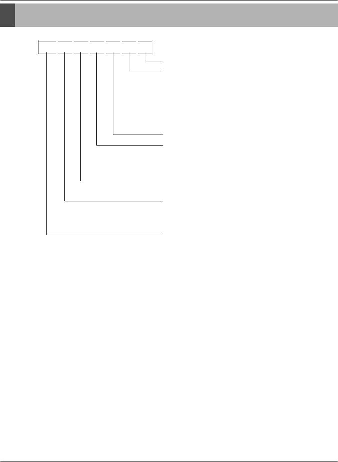
Nomenclature
3. Nomenclature
ARN 
 U
U 
 07
07 
 G
G 
 TJ
TJ 
 A
A 
 2
2
Serial Number
Combinations of functions
A:Basic function
L:Neo Plasma(Wall Mounted)
C:Plasma(Ceiling Cassette)
G: Low Static
ART COOL Type Panel Color
B:Blue D:Wood M:Metal R:Mirror W:White Wood
V: Silver E:Red G:Gold 1: Kiss (Photo changeable)
Chassis Name |
|
Electrical Ratings |
|
1:1Ø, 115V, 60Hz |
2: 1Ø, 220V, 60Hz |
6:1Ø, 220 ~ 240V, 50Hz |
7: 1Ø, 100V, 50/60Hz |
G:1Ø, 220 ~ 240V, 50Hz / 220V 60Hz
Total Cooling Capacity in Btu/h
EX) 5,000 Btu/h '05' 18,000 Btu/h '18'
Combination of Inverter Type and Cooling Only or Heat Pump
N: AC Inverter and H/P V: AC Inverter and C/O U: DC Inverter and H/P and C/O


 System with Indoor Unit using R410A
LGETA:U Ex) URN
Copyright ©2008 LG Electronics. Inc. All right reserved. |
- 6 - |
Only for training and service purposes |
LGE Internal Use Only |
|

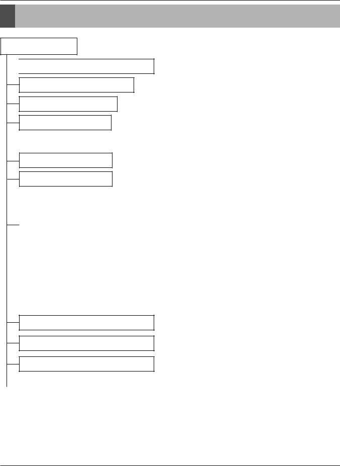
Part 2 |
|
Indoor Units |
|
Ceiling Cassette |
|
1 Way ................................................................................. |
8 |
2 Way ............................................................................... |
13 |
4 Way(1)........................................................................... |
20 |
4 Way(2)........................................................................... |
23 |
Art Cool Series |
|
ART COOL Miror ............................................................. |
30 |
ART COOL Gallery .......................................................... |
41 |
Ceiling Concealed Duct |
|
Low Static ........................................................................ |
51 |
Built In .............................................................................. |
57 |
High Static........................................................................ |
63 |
Wall Mounted(General) |
|
Wall Mounted ................................................................... |
72 |
Ceiling & Floor |
|
Ceiling & Floor |
|
Ceiling Suspended........................................................... |
83 |
Floor Standing |
|
Floor Standing.................................................................. |
90 |
Copyright ©2008 LG Electronics. Inc. All right reserved. |
- 7 - |
Only for training and service purposes |
LGE Internal Use Only |
|

Ceiling Mounted Cassette Type (1Way)
1. |
Functions ...................................................................................... |
9 |
2. |
Operation Details........................................................................ |
10 |
3. |
Dimensions ................................................................................. |
12 |
Copyright ©2008 LG Electronics. Inc. All right reserved. |
- 8 - |
Only for training and service purposes |
LGE Internal Use Only |
|
Specification
1. Functions
Indoor Unit
 Operation ON/OFF by Remote controller
Sensing the Room Temperature • Room temperature sensor. (Thermistor)
Room temperature control • Maintains the room temperature in accordance with the Setting Temperature.
Starting Current Control • Indoor fan is delayed for 5 seconds at the starting.
|
Indoor Fan Speed Control |
• Jet, High, Med, Low, Lolow |
|
||
|
|
|
Soft Dry Operation Mode • Intermittent operation of fan at low speed.
Airflow Direction Control • The louver can be set at swing up and down automatically.
|
Auto Restart |
• Although the air-conditioner is turned off by a power failure, it is restarted auto- |
||
|
||||
|
|
matically previous operation mode after power supply. |
||
|
|
|||
|
|
|
|
|
|
Deice (defrost) control (Heating) |
• Both the indoor and outdoor fan stops during defrosting. |
||
|
|
|
• Hot start after defrost ends. |
|
|
|
|
||
|
|
|
|
• The indoor fan does not rotate until the evaporator pip- |
|
Hot-start Control (Heating) |
|
||
|
|
|||
|
|
ing temperature will be reached at 25°C. |
||
|
|
|
|
|
|
|
|
|
• To install a unit is very convenient because of smaller |
|
Compact and light design |
|
||
|
|
size than textile. |
||
|
|
|
|
|
|
|
|
|
• The most advanced low-noise design. |
|
Low noise |
|
|
|
|
|
|
• The adoption of turbo fan and round type heat exchang- |
|
|
|
|
|
|
|
|
|
|
er give the quietest operation. |
Long life filter
High head Drain pump
High-Ceiling corresponding Function
•Long life wrinkle(type) and washable and anti-bacteria filter is adopted.
•Built-in drain pump automatically drains water.
•A standard drain-head height of up to 700mm is possible.
•According to the height of ceiling, the RPM of indoor fan motor is selected to increase air reaching distance.
|
Central Control(Optional) |
• It is operating individually or totally by central control function. |
|
||
|
|
|
Copyright ©2008 LG Electronics. Inc. All right reserved. |
- 9 - |
Only for training and service purposes |
LGE Internal Use Only |
|

Operation Detail
2. Operation Detail

 (1)
(1) The
The function
 of
of main
main control


■ Auto Swing Control
• This function is to swing the louver up and down automatically.
■ Soft-Dry Operation
• The indoor fan speed is automatically set to the low, so the shift of the indoor fan speed is impossible because of already being set to the best speed for Dry Operation by microcontroller control.
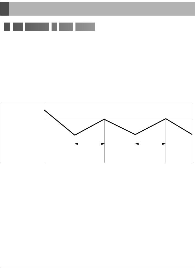
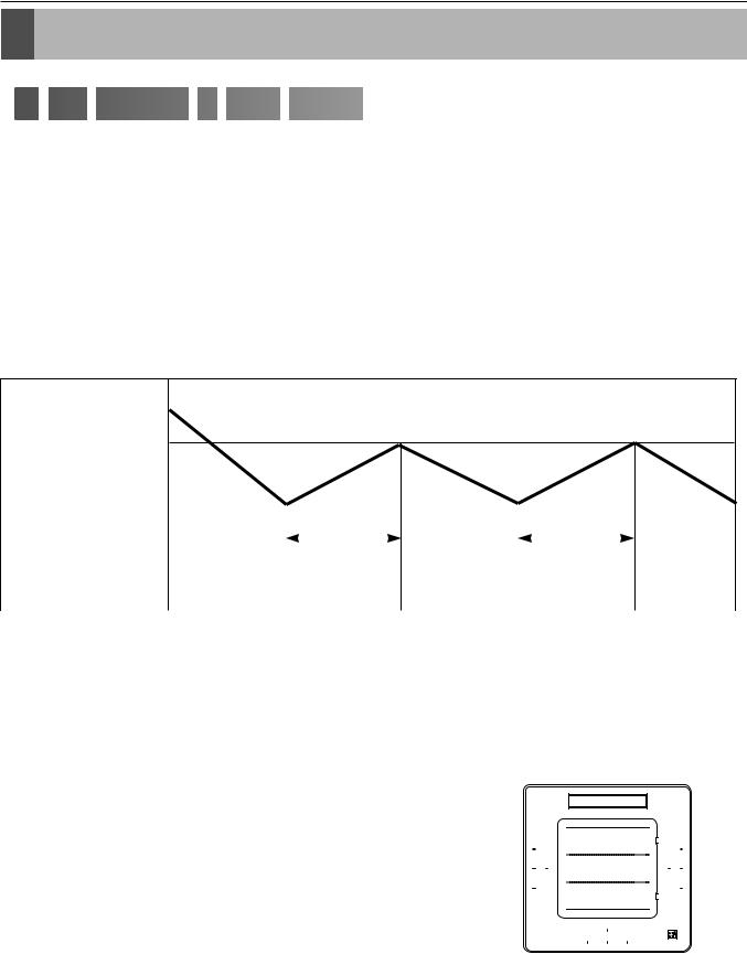
■ Cooling Mode Operation
•When selecting the Cooling(  ) Mode Operation, the unit will operate according to the setting by the remote controller and the operation diagram is as following
Intake Air Temperature
Thermo. ON
(SET TEMPERATURE +0.5°C)
Thermo. OFF |
|
|
|
|
|
|
|
|
|
|
|
|
|
|
|
|
|
|
|
|
|
|
|
|
|
|
|
|
|
(SET TEMPERATURE -0.5°C) |
|
|
|
More than |
|
|
|
|
More than |
|
|
|||
|
|
|
|
|
|
|
|
|
|
|
|
|
|
|
|
|
|
|
|
3 minutes |
|
|
|
3 minutes |
|
|
|||
|
|
|
|
|
|
|
|
|
|
|
|
|
||
INDOOR FAN |
Selected |
|
|
Low |
Selected |
|
|
Low |
Selected |
|||||
Speed |
|
|
Speed |
|
|
Speed |
||||||||
|
|
|
|
|
|
|
|
|
|
|||||
|
|
|
|
|
|
|
|
|
|
|
|
|
|
|
|
|
|
|
|
|
|
|
|
|
|
|
|
|
|
|
|
|
Thermal ON |
|
|
|
|
Thermal OFF |
|
|
||||
|
|
|
|
|
|
|
|
|
|
|
|
|
|
|
Indoor Unit mode |
|
|
|
ST+0.5 |
|
|
|
|
ST-0.5 |
|
|
|||
|
|
|
|
|
|
|
|
|
|
|
|
|
||
2TH (Remo.+Indoor) |
To be selected higher temperature |
|
|
To be selected higher temperature |
||||||||||
contrast Indoor Unit and Remo. |
|
|
contrast Indoor Unit and Remo. |
|||||||||||
|
|
|
|
|||||||||||
|
|
|
|
|
|
|
|
|
|
|
|
|
|
|
Remo. Mode |
|
|
|
ST+0.5 |
|
|
|
|
ST-0.5 |
|
|
|||
|
|
|
|
|
|
|
|
|
|
|
|
|
|
|
Copyright ©2008 LG Electronics. Inc. All right reserved. |
- 10 - |
Only for training and service purposes |
LGE Internal Use Only |
|
Operation Detail
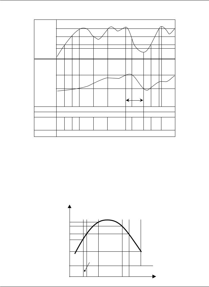
■ Heating Mode Operation
The unit will operate according to the setting by the remote controller and the operation diagram is shown as following.
Indoor pipe Temperature
36(42)°C
33(39)°C |
|
|
|
|
|
|
|
25°C |
|
|
|
|
|
|
|
22(20)°C |
|
|
|
|
|
|
|
Room |
|
|
|
|
|
|
|
Temperature |
|
|
|
|
|
|
|
Thermal Off |
|
|
|
|
|
|
|
Thermal On |
|
|
|
|
|
|
|
|
|
|
|
|
Minimum |
|
|
|
|
|
|
|
3min |
|
|
Thermal |
|
ON |
|
|
OFF |
ON |
|
Outdoor fan |
|
ON |
|
|
OFF |
ON |
|
Indoor fan |
Stop Low Low |
Setting |
Low |
Setting |
Low Stop |
Stop Low |
Setting |
fan |
fan |
fan |
|||||
|
|
speed |
|
speed |
|
|
speed |
4 Way |
|
|
|
ON |
|
|
|
|
Thermal ON |
Thermal OFF |
Indoor Unit mode |
ST+2 |
ST+4 |
|
|
|
2TH |
To be selected lower temperature |
To be selected lower temperature |
(Remo.+Indoor) |
contrast Indoor Unit and Remo. |
contrast Indoor Unit and Remo. |
|
|
|
Remo. mode |
ST+0 |
ST+2 |
|
|
|
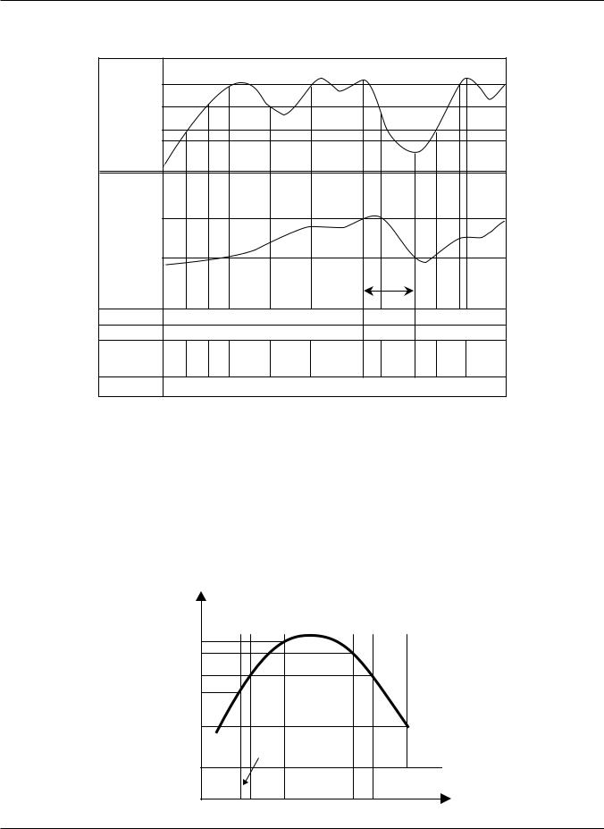
■ Hot-start Control
 The indoor fan does no rotate until the evaporator piping temperature will be reached to 25°C.
  The operation diagram is as following.
Pipe |
|
|
|
|
|
|
temperature |
|
|
|
|
|
|
35 °C |
|
|
|
|
|
|
30 °C |
|
|
|
|
|
|
27 °C |
|
|
|
|
|
|
25 °C |
|
|
|
|
|
|
22 °C |
|
LO |
|
|
|
|
|
|
|
|
|
||
|
|
LOW |
|
|
|
|
Indoor fan |
OFF |
LOW |
SELECTED |
LOW |
LOLOW |
|
speed |
FAN |
|||||
|
|
|
|
|||
COMP |
|
|
ON |
|
|
Copyright ©2008 LG Electronics. Inc. All right reserved. |
- 11 - |
Only for training and service purposes |
LGE Internal Use Only |
|

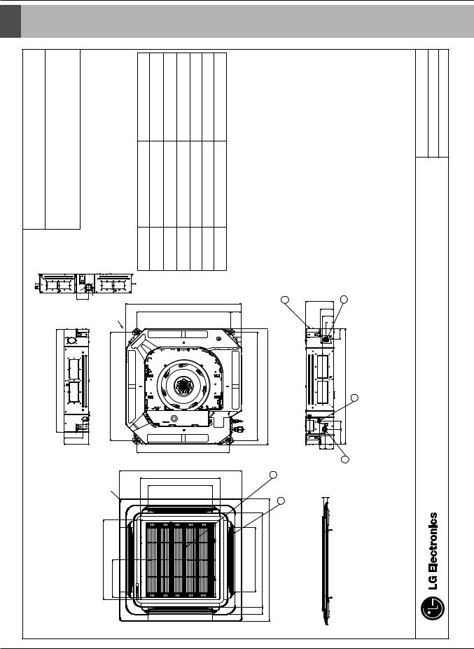
Dimensions
3. Dimensions
|
|
(unit : mm) |
|
|
|
|
|
|
|
|
|
|
|
|
|
Ceiling Cassette 1-way |
ARNU07GTJ*2 ARNU09GTJ*2 ARNU12GTJ*2 |
Descripition |
ø6.35 flare |
ø12.7 flare |
|
|
|
|
|
|
Unit should be installed in compliance with the installation manual |
|
Unit shall be grounded in accordance with the local regulations or |
|
|
|
Name |
Liquid pipe connection |
Gas pipe connection |
Air suction grill |
Air discharge grill |
|
|
|
|
in the product box. |
applicable national codes. |
||||
|
|
|
Number |
1 |
2 |
3 |
4 |
|
Note |
||||||
|
|
|
|
||||||||||||
|
|
|
|
|
|
|
|
|
|
|
|
1. |
|
2. |
|
|
|
|
|
|
|
|
|
|
|
|
|
|
|
||
30 |
36 50 |
83 |
56 |
|
|
100 |
|
|
151 |
|
|
173 |
|
|
5.242 |
|
|
1 |
|
|
2 |
|
|
961.2 |
860 |
|
1070 |
939 |
|
|
16.4. |
110 |
|
|
|
131 |
|
|
|
16.5 |
198.8 |
|
|
|
19.1 |
|
|
|
32.8 |
4.344 |
|
|
410 |
|
|
83 |
138 |
76, Seongsan-dong, Changwon City, Gyeongnam, CHASSIS CODE: TJ 641-713, Korea www.lgeaircon.com
4 |
3 |
480
Copyright ©2008 LG Electronics. Inc. All right reserved. |
- 12 - |
Only for training and service purposes |
LGE Internal Use Only |
|

Ceiling Mounted Cassette Type (2Way)
1. |
Functions .................................................................................... |
14 |
2. |
Operation Details........................................................................ |
15 |
3. |
Dimensions ................................................................................. |
17 |
Copyright ©2008 LG Electronics. Inc. All right reserved. |
- 13 - |
Only for training and service purposes |
LGE Internal Use Only |
|

Functions
1. Functions
Indoor Unit
 Operation ON/OFF by Remote controller
Sensing the Room Temperature • Room temperature sensor. (Thermistor)
Room temperature control • Maintains the room temperature in accordance with the Setting Temperature.
Starting Current Control • Indoor fan is delayed for 5 seconds at the starting.
|
Indoor Fan Speed Control |
• Jet, High, Med, Low, Lolow |
|
||
|
|
|
Soft Dry Operation Mode • Intermittent operation of fan at low speed.
Airflow Direction Control • The louver can be set at swing up and down automatically.
|
Auto Restart |
• Although the air-conditioner is turned off by a power failure, it is restarted auto- |
||
|
||||
|
|
matically previous operation mode after power supply. |
||
|
|
|||
|
|
|
|
|
|
Deice (defrost) control (Heating) |
• Both the indoor and outdoor fan stops during defrosting. |
||
|
|
|
• Hot start after defrost ends. |
|
|
|
|
||
|
|
|
|
• The indoor fan does not rotate until the evaporator pip- |
|
Hot-start Control (Heating) |
|
||
|
|
|||
|
|
ing temperature will be reached at 25°C. |
||
|
|
|
|
|
|
|
|
|
• To install a unit is very convenient because of smaller |
|
Compact and light design |
|
||
|
|
size than textile. |
||
|
|
|
|
|
|
|
|
|
• The most advanced low-noise design. |
|
Low noise |
|
|
|
|
|
|
• The adoption of turbo fan and round type heat exchang- |
|
|
|
|
|
|
|
|
|
|
er give the quietest operation. |
Long life filter
High head Drain pump
High-Ceiling corresponding Function
•Long life wrinkle(type) and washable and anti-bacteria filter is adopted.
•Built-in drain pump automatically drains water.
•A standard drain-head height of up to 700mm is possible.
•According to the height of ceiling, the RPM of indoor fan motor is selected to increase air reaching distance.
|
Central Control(Optional) |
• It is operating individually or totally by central control function. |
|
||
|
|
|
Copyright ©2008 LG Electronics. Inc. All right reserved. |
- 14 - |
Only for training and service purposes |
LGE Internal Use Only |
|
Operation Detail
2. Operation Detail

 (1)
(1) The
The function
 of
of main
main control


■ Auto Swing Control
• This function is to swing the louver up and down automatically.
■ Soft-Dry Operation
• The indoor fan speed is automatically set to the low, so the shift of the indoor fan speed is impossible because of already being set to the best speed for Dry Operation by microcontroller control.
■ Cooling Mode Operation
•When selecting the Cooling(  ) Mode Operation, the unit will operate according to the setting by the remote controller and the operation diagram is as following
Intake Air Temperature
Thermo. ON
(SET TEMPERATURE +0.5°C)
Thermo. OFF |
|
|
|
|
|
|
|
|
|
|
|
|
|
|
|
|
|
|
|
|
|
|
|
|
|
|
|
|
|
(SET TEMPERATURE -0.5°C) |
|
|
|
More than |
|
|
|
|
More than |
|
|
|||
|
|
|
|
|
|
|
|
|
|
|
|
|
|
|
|
|
|
|
|
3 minutes |
|
|
|
3 minutes |
|
|
|||
|
|
|
|
|
|
|
|
|
|
|
|
|
||
INDOOR FAN |
Selected |
|
|
Low |
Selected |
|
|
Low |
Selected |
|||||
Speed |
|
|
Speed |
|
|
Speed |
||||||||
|
|
|
|
|
|
|
|
|
|
|||||
|
|
|
|
|
|
|
|
|
|
|
|
|
|
|
|
|
|
|
|
|
|
|
|
|
|
|
|
|
|
|
|
|
Thermal ON |
|
|
|
|
Thermal OFF |
|
|
||||
|
|
|
|
|
|
|
|
|
|
|
|
|
|
|
Indoor Unit mode |
|
|
|
ST+0.5 |
|
|
|
|
ST-0.5 |
|
|
|||
|
|
|
|
|
|
|
|
|
|
|
|
|
||
2TH (Remo.+Indoor) |
To be selected higher temperature |
|
|
To be selected higher temperature |
||||||||||
contrast Indoor Unit and Remo. |
|
|
contrast Indoor Unit and Remo. |
|||||||||||
|
|
|
|
|||||||||||
|
|
|
|
|
|
|
|
|
|
|
|
|
|
|
Remo. Mode |
|
|
|
ST+0.5 |
|
|
|
|
ST-0.5 |
|
|
|||
|
|
|
|
|
|
|
|
|
|
|
|
|
|
|
Copyright ©2008 LG Electronics. Inc. All right reserved. |
- 15 - |
Only for training and service purposes |
LGE Internal Use Only |
|
Operation Detail
■ Heating Mode Operation
The unit will operate according to the setting by the remote controller and the operation diagram is shown as following.
Indoor pipe Temperature
36(42)°C
33(39)°C |
|
|
|
|
|
|
|
25°C |
|
|
|
|
|
|
|
22(20)°C |
|
|
|
|
|
|
|
Room |
|
|
|
|
|
|
|
Temperature |
|
|
|
|
|
|
|
Thermal Off |
|
|
|
|
|
|
|
Thermal On |
|
|
|
|
|
|
|
|
|
|
|
|
Minimum |
|
|
|
|
|
|
|
3min |
|
|
Thermal |
|
ON |
|
|
OFF |
ON |
|
Outdoor fan |
|
ON |
|
|
OFF |
ON |
|
Indoor fan |
Stop Low Low |
Setting |
Low |
Setting |
Low Stop |
Stop Low |
Setting |
fan |
fan |
fan |
|||||
|
|
speed |
|
speed |
|
|
speed |
4 Way |
|
|
|
ON |
|
|
|
|
Thermal ON |
Thermal OFF |
Indoor Unit mode |
ST+2 |
ST+4 |
|
|
|
2TH |
To be selected lower temperature |
To be selected lower temperature |
(Remo.+Indoor) |
contrast Indoor Unit and Remo. |
contrast Indoor Unit and Remo. |
|
|
|
Remo. mode |
ST+0 |
ST+2 |
|
|
|
■ Hot-start Control
 The indoor fan does no rotate until the evaporator piping temperature will be reached to 25°C.
  The operation diagram is as following.
Pipe |
|
|
|
|
|
|
temperature |
|
|
|
|
|
|
35 °C |
|
|
|
|
|
|
30 °C |
|
|
|
|
|
|
27 °C |
|
|
|
|
|
|
25 °C |
|
|
|
|
|
|
22 °C |
|
LO |
|
|
|
|
|
|
|
|
|
||
|
|
LOW |
|
|
|
|
Indoor fan |
OFF |
LOW |
SELECTED |
LOW |
LOLOW |
|
speed |
FAN |
|||||
|
|
|
|
|||
COMP |
|
|
ON |
|
|
Copyright ©2008 LG Electronics. Inc. All right reserved. |
- 16 - |
Only for training and service purposes |
LGE Internal Use Only |
|

and training for Only |
LG ©2008 Copyright |
purposes service |
All .Inc .Electronics |
|
.reserved right |
- 17 -
Only Use Internal LGE
4
3
Ceiling Cassette 2-way
ARNU18GTL*2
ARNU24GTL*2
|
A |
830 |
B |
47.9
(unit : mm)
|
|
Number |
Name |
Descripition |
275 |
|
1 |
Liquid pipe connection |
(18k) ø6.35, (24k)ø9.52 |
|
|
|||
2 |
|
2 |
Gas pipe connection |
(18k) ø12.7, (24k)ø15.88 |
550 |
|
|||
|
3 |
Air suction grill |
|
|
69.5 |
|
|
||
|
|
|
||
1 |
|
4 |
Air discharge grill |
|
|
|
|
|
|
|
|
Note |
|
|
889.2 |
|
1. Unit should be installed in compliance with the installation manual |
||
|
in the product box. |
|
||
|
TL |
2. Unit shall be grounded in accordance with the local regulations or |
||
A |
225 |
applicable national codes. |
|
|
B |
126.5 |
|
|
|
1050
28.5
640
76, Seongsan-dong, Changwon City, Gyeongnam, |
CHASSIS CODE: TL |
641-713, Korea |
|
www.lgeaircon.com |
|
|
|
|
|
Dimensions .3
Dimensions

Ceiling Mounted Cassette Type (4Way) (1)
1. |
Functions .................................................................................... |
19 |
2. |
Operation Details........................................................................ |
20 |
3. |
Dimensions ................................................................................. |
22 |
Copyright ©2008 LG Electronics. Inc. All right reserved. |
- 18 - |
Only for training and service purposes |
LGE Internal Use Only |
|
Functions
1. Functions
Indoor Unit
 Operation ON/OFF by Remote controller
Sensing the Room Temperature • Room temperature sensor. (Thermistor)
Room temperature control • Maintains the room temperature in accordance with the Setting Temperature.
Starting Current Control • Indoor fan is delayed for 5 seconds at the starting.
|
Indoor Fan Speed Control |
• Jet, High, Med, Low, Lolow |
|
||
|
|
|
Soft Dry Operation Mode • Intermittent operation of fan at low speed.
Airflow Direction Control • The louver can be set at swing up and down automatically.
|
Auto Restart |
• Although the air-conditioner is turned off by a power failure, it is restarted auto- |
||
|
||||
|
|
matically previous operation mode after power supply. |
||
|
|
|||
|
|
|
|
|
|
Deice (defrost) control (Heating) |
• Both the indoor and outdoor fan stops during defrosting. |
||
|
|
|
• Hot start after defrost ends. |
|
|
|
|
||
|
|
|
|
• The indoor fan does not rotate until the evaporator pip- |
|
Hot-start Control (Heating) |
|
||
|
|
|||
|
|
ing temperature will be reached at 25°C. |
||
|
|
|
|
|
|
|
|
|
• To install a unit is very convenient because of smaller |
|
Compact and light design |
|
||
|
|
size than textile. |
||
|
|
|
|
|
|
|
|
|
• The most advanced low-noise design. |
|
Low noise |
|
|
|
|
|
|
• The adoption of turbo fan and round type heat exchang- |
|
|
|
|
|
|
|
|
|
|
er give the quietest operation. |
Long life filter
High head Drain pump
High-Ceiling corresponding Function
•Long life wrinkle(type) and washable and anti-bacteria filter is adopted.
•Built-in drain pump automatically drains water.
•A standard drain-head height of up to 700mm is possible.
•According to the height of ceiling, the RPM of indoor fan motor is selected to increase air reaching distance.
|
Central Control(Optional) |
• It is operating individually or totally by central control function. |
|
||
|
|
|
|
|
|
|
Swirl Swing Control |
• It is operating swirl swing |
|
||
|
|
|
Copyright ©2008 LG Electronics. Inc. All right reserved. |
- 19 - |
Only for training and service purposes |
LGE Internal Use Only |
|

Operation Detail
2. Operation Detail

 (1)
(1) The
The function
 of
of main
main control


■ Auto Swing Control
• This function is to swing the louver up and down automatically.
■ Soft-Dry Operation
• The indoor fan speed is automatically set to the low, so the shift of the indoor fan speed is impossible because of already being set to the best speed for Dry Operation by microcontroller control.
■ Cooling Mode Operation
•When selecting the Cooling(  ) Mode Operation, the unit will operate according to the setting by the remote controller and the operation diagram is as following
Intake Air Temperature
Thermo. ON
(SET TEMPERATURE +0.5°C)
Thermo. OFF |
|
|
|
|
|
|
|
|
|
|
|
|
|
|
|
|
|
|
|
|
|
|
|
|
|
|
|
|
|
(SET TEMPERATURE -0.5°C) |
|
|
|
More than |
|
|
|
|
More than |
|
|
|||
|
|
|
|
|
|
|
|
|
|
|
|
|
|
|
|
|
|
|
|
3 minutes |
|
|
|
3 minutes |
|
|
|||
|
|
|
|
|
|
|
|
|
|
|
|
|
||
INDOOR FAN |
Selected |
|
|
Low |
Selected |
|
|
Low |
Selected |
|||||
Speed |
|
|
Speed |
|
|
Speed |
||||||||
|
|
|
|
|
|
|
|
|
|
|||||
|
|
|
|
|
|
|
|
|
|
|
|
|
|
|
|
|
|
|
|
|
|
|
|
|
|
|
|
|
|
|
|
|
Thermal ON |
|
|
|
|
Thermal OFF |
|
|
||||
|
|
|
|
|
|
|
|
|
|
|
|
|
|
|
Indoor Unit mode |
|
|
|
ST+0.5 |
|
|
|
|
ST-0.5 |
|
|
|||
|
|
|
|
|
|
|
|
|
|
|
|
|
||
2TH (Remo.+Indoor) |
To be selected higher temperature |
|
|
To be selected higher temperature |
||||||||||
contrast Indoor Unit and Remo. |
|
|
contrast Indoor Unit and Remo. |
|||||||||||
|
|
|
|
|||||||||||
|
|
|
|
|
|
|
|
|
|
|
|
|
|
|
Remo. Mode |
|
|
|
ST+0.5 |
|
|
|
|
ST-0.5 |
|
|
|||
|
|
|
|
|
|
|
|
|
|
|
|
|
|
|
■ Swirl Swing Control |
|
Vane 2 |
|||||||
|
|
|
|
|
|
||||
Vane 2, |
4 is almost vane closed while vane1, 3 is opened. |
|
|
|
|
|
|||
Vane 1, |
3 and vane 2,4 turn over minutely |
|
|
|
|
|
|
||
|
|
|
|
|
|
||||
|
Vane 1 |
|
|
|
|
|
|
|
Vane 3 |
|
|
|
|
|
|
|
|
||
|
|
|
|
|
|
|
|
||
|
|
|
|
|
|
|
|
|
|
|
|
|
|
|
|
|
|
|
|
|
|
|
|
|
|
|
|
|
|
|
|
|
|
|
|
|
|
|
|
|
|
|
|
|
|
|
|
|
|
|
Vane 4 |
|
|
Copyright ©2008 LG Electronics. Inc. All right reserved. |
- 20 - |
Only for training and service purposes |
LGE Internal Use Only |
|
Operation Detail
■ Heating Mode Operation
The unit will operate according to the setting by the remote controller and the operation diagram is shown as following.
Indoor pipe Temperature
36(42)°C
33(39)°C |
|
|
|
|
|
|
|
25°C |
|
|
|
|
|
|
|
22(20)°C |
|
|
|
|
|
|
|
Room |
|
|
|
|
|
|
|
Temperature |
|
|
|
|
|
|
|
Thermal Off |
|
|
|
|
|
|
|
Thermal On |
|
|
|
|
|
|
|
|
|
|
|
|
Minimum |
|
|
|
|
|
|
|
3min |
|
|
Thermal |
|
ON |
|
|
OFF |
ON |
|
Outdoor fan |
|
ON |
|
|
OFF |
ON |
|
Indoor fan |
Stop Low Low |
Setting |
Low |
Setting |
Low Stop |
Stop Low |
Setting |
fan |
fan |
fan |
|||||
|
|
speed |
|
speed |
|
|
speed |
4 Way |
|
|
|
ON |
|
|
|
|
Thermal ON |
Thermal OFF |
Indoor Unit mode |
ST+2 |
ST+4 |
|
|
|
2TH |
To be selected lower temperature |
To be selected lower temperature |
(Remo.+Indoor) |
contrast Indoor Unit and Remo. |
contrast Indoor Unit and Remo. |
|
|
|
Remo. mode |
ST+0 |
ST+2 |
|
|
|
■ Hot-start Control
 The indoor fan does no rotate until the evaporator piping temperature will be reached to 25°C.
  The operation diagram is as following.
Pipe |
|
|
|
|
|
|
temperature |
|
|
|
|
|
|
35 °C |
|
|
|
|
|
|
30 °C |
|
|
|
|
|
|
27 °C |
|
|
|
|
|
|
25 °C |
|
|
|
|
|
|
22 °C |
|
LO |
|
|
|
|
|
|
|
|
|
||
|
|
LOW |
|
|
|
|
Indoor fan |
OFF |
LOW |
SELECTED |
LOW |
LOLOW |
|
speed |
FAN |
|||||
|
|
|
|
|||
COMP |
|
|
ON |
|
|
Copyright ©2008 LG Electronics. Inc. All right reserved. |
- 21 - |
Only for training and service purposes |
LGE Internal Use Only |
|

and training for Only |
LG ©2008 Copyright |
purposes service |
All .Inc .Electronics |
|
.reserved right |
- 22 -
Only Use Internal LGE
269
670
670
670 |
|
570 |
|
|
450 |
|
5 |
|
670 |
570 |
521 |
|
6 |
|
Ceiling Cassette 4-way
ARNU07GTE*2
ARNU09GTE*2
ARNU12GTE*2
ARNU15GTE*2
ARNU18GTE*2
(unit : mm)
Number |
Name |
Descripition |
|
|
|
1 |
Liquid pipe connection |
Unit size(7k, 9k, 12k, 18k):ø6.35 |
|
|
|
2 |
Gas pipe connection |
Unit size(7k, 9k, 12k, 18k):ø12.7 |
|
|
|
3 |
Drain pipe connection |
|
|
|
|
4 |
Power supply connection |
|
|
|
|
5 |
Air discharge grill |
|
|
|
|
6 |
Air suction grill |
|
Note
1.Unit should be installed in compliance with the installation manual in the product box.
2.Unit shall be grounded in accordance with the local regulations or applicable national codes.
|
|
4 |
40 |
|
|
|
|
|
|
|
|
|
|
30 |
|
1 |
2 |
|
|
|
|
|
|
|
|
|
110 |
110 |
|
30 |
269 |
.4 |
90 |
90 |
|
|
|
120 |
|
|
|
|
|
|
3 |
|
|
|
76, Seongsan-dong, Changwon City, Gyeongnam, |
CHASSIS CODE: TE |
|
641-713, Korea |
|
|
www.lgeaircon.com |
|
|
|
|
|
|
|
|
|
Dimensions |
.3 |
|
|
Dimensions |
||
|
|
|

Ceiling Mounted Cassette Type (4Way) (2)
1. |
Functions .................................................................................... |
24 |
2. |
Operation Details........................................................................ |
25 |
3. |
Dimensions ................................................................................. |
27 |
Copyright ©2008 LG Electronics. Inc. All right reserved. |
- 23 - |
Only for training and service purposes |
LGE Internal Use Only |
|

Functions
1. Functions
Indoor Unit
 Operation ON/OFF by Remote controller
Sensing the Room Temperature • Room temperature sensor. (Thermistor)
Room temperature control • Maintains the room temperature in accordance with the Setting Temperature.
Starting Current Control • Indoor fan is delayed for 5 seconds at the starting.
|
Indoor Fan Speed Control |
• Jet, High, Med, Low, Lolow |
|
||
|
|
|
Soft Dry Operation Mode • Intermittent operation of fan at low speed.
Airflow Direction Control • The louver can be set at swing up and down automatically.
|
Auto Restart |
• Although the air-conditioner is turned off by a power failure, it is restarted auto- |
||
|
||||
|
|
matically previous operation mode after power supply. |
||
|
|
|||
|
|
|
|
|
|
Deice (defrost) control (Heating) |
• Both the indoor and outdoor fan stops during defrosting. |
||
|
|
|
• Hot start after defrost ends. |
|
|
|
|
||
|
|
|
|
• The indoor fan does not rotate until the evaporator pip- |
|
Hot-start Control (Heating) |
|
||
|
|
|||
|
|
ing temperature will be reached at 25°C. |
||
|
|
|
|
|
|
|
|
|
• To install a unit is very convenient because of smaller |
|
Compact and light design |
|
||
|
|
size than textile. |
||
|
|
|
|
|
|
|
|
|
• The most advanced low-noise design. |
|
Low noise |
|
|
|
|
|
|
• The adoption of turbo fan and round type heat exchang- |
|
|
|
|
|
|
|
|
|
|
er give the quietest operation. |
Long life filter
High head Drain pump
High-Ceiling corresponding Function
•Long life wrinkle(type) and washable and anti-bacteria filter is adopted.
•Built-in drain pump automatically drains water.
•A standard drain-head height of up to 700mm is possible.
•According to the height of ceiling, the RPM of indoor fan motor is selected to increase air reaching distance.
|
Central Control(Optional) |
• It is operating individually or totally by central control function. |
|
||
|
|
|
|
|
|
|
Swirl Swing Control |
• It is operating swirl swing |
|
||
|
|
|
Copyright ©2008 LG Electronics. Inc. All right reserved. |
- 24 - |
Only for training and service purposes |
LGE Internal Use Only |
|
Operation Detail
2. Operation Detail

 (1)
(1) The
The function
 of
of main
main control


■ Auto Swing Control
• This function is to swing the louver up and down automatically.
■ Soft-Dry Operation
• The indoor fan speed is automatically set to the low, so the shift of the indoor fan speed is impossible because of already being set to the best speed for Dry Operation by microcontroller control.
■ Cooling Mode Operation
•When selecting the Cooling(  ) Mode Operation, the unit will operate according to the setting by the remote controller and the operation diagram is as following
Intake Air Temperature
Thermo. ON
(SET TEMPERATURE +0.5°C)
Thermo. OFF |
|
|
|
|
|
|
|
|
|
|
|
|
|
|
|
|
|
|
|
|
|
|
|
|
|
|
|
|
|
(SET TEMPERATURE -0.5°C) |
|
|
|
More than |
|
|
|
|
More than |
|
|
|||
|
|
|
|
|
|
|
|
|
|
|
|
|
|
|
|
|
|
|
|
3 minutes |
|
|
|
3 minutes |
|
|
|||
|
|
|
|
|
|
|
|
|
|
|
|
|
||
INDOOR FAN |
Selected |
|
|
Low |
Selected |
|
|
Low |
Selected |
|||||
Speed |
|
|
Speed |
|
|
Speed |
||||||||
|
|
|
|
|
|
|
|
|
|
|||||
|
|
|
|
|
|
|
|
|
|
|
|
|
|
|
|
|
|
|
|
|
|
|
|
|
|
|
|
|
|
|
|
|
Thermal ON |
|
|
|
|
Thermal OFF |
|
|
||||
|
|
|
|
|
|
|
|
|
|
|
|
|
|
|
Indoor Unit mode |
|
|
|
ST+0.5 |
|
|
|
|
ST-0.5 |
|
|
|||
|
|
|
|
|
|
|
|
|
|
|
|
|
||
2TH (Remo.+Indoor) |
To be selected higher temperature |
|
|
To be selected higher temperature |
||||||||||
contrast Indoor Unit and Remo. |
|
|
contrast Indoor Unit and Remo. |
|||||||||||
|
|
|
|
|||||||||||
|
|
|
|
|
|
|
|
|
|
|
|
|
|
|
Remo. Mode |
|
|
|
ST+0.5 |
|
|
|
|
ST-0.5 |
|
|
|||
|
|
|
|
|
|
|
|
|
|
|
|
|
|
|
■ Swirl Swing Control |
|
Vane 2 |
|||||||
|
|
|
|
|
|
||||
Vane 2, |
4 is almost vane closed while vane1, 3 is opened. |
|
|
|
|
|
|||
Vane 1, |
3 and vane 2,4 turn over minutely |
|
|
|
|
|
|
||
|
|
|
|
|
|
||||
|
Vane 1 |
|
|
|
|
|
|
|
Vane 3 |
|
|
|
|
|
|
|
|
||
|
|
|
|
|
|
|
|
||
|
|
|
|
|
|
|
|
|
|
|
|
|
|
|
|
|
|
|
|
|
|
|
|
|
|
|
|
|
|
|
|
|
|
|
|
|
|
|
|
|
|
|
|
|
|
|
|
|
|
|
Vane 4 |
|
|
Copyright ©2008 LG Electronics. Inc. All right reserved. |
- 25 - |
Only for training and service purposes |
LGE Internal Use Only |
|
Operation Detail
■ Heating Mode Operation
The unit will operate according to the setting by the remote controller and the operation diagram is shown as following.
Indoor pipe Temperature
36(42)°C
33(39)°C |
|
|
|
|
|
|
|
25°C |
|
|
|
|
|
|
|
22(20)°C |
|
|
|
|
|
|
|
Room |
|
|
|
|
|
|
|
Temperature |
|
|
|
|
|
|
|
Thermal Off |
|
|
|
|
|
|
|
Thermal On |
|
|
|
|
|
|
|
|
|
|
|
|
Minimum |
|
|
|
|
|
|
|
3min |
|
|
Thermal |
|
ON |
|
|
OFF |
ON |
|
Outdoor fan |
|
ON |
|
|
OFF |
ON |
|
Indoor fan |
Stop Low Low |
Setting |
Low |
Setting |
Low Stop |
Stop Low |
Setting |
fan |
fan |
fan |
|||||
|
|
speed |
|
speed |
|
|
speed |
4 Way |
|
|
|
ON |
|
|
|
|
Thermal ON |
Thermal OFF |
Indoor Unit mode |
ST+2 |
ST+4 |
|
|
|
2TH |
To be selected lower temperature |
To be selected lower temperature |
(Remo.+Indoor) |
contrast Indoor Unit and Remo. |
contrast Indoor Unit and Remo. |
|
|
|
Remo. mode |
ST+0 |
ST+2 |
|
|
|
■ Hot-start Control
 The indoor fan does no rotate until the evaporator piping temperature will be reached to 25°C.
  The operation diagram is as following.
Pipe |
|
|
|
|
|
|
temperature |
|
|
|
|
|
|
35 °C |
|
|
|
|
|
|
30 °C |
|
|
|
|
|
|
27 °C |
|
|
|
|
|
|
25 °C |
|
|
|
|
|
|
22 °C |
|
LO |
|
|
|
|
|
|
|
|
|
||
|
|
LOW |
|
|
|
|
Indoor fan |
OFF |
LOW |
SELECTED |
LOW |
LOLOW |
|
speed |
FAN |
|||||
|
|
|
|
|||
COMP |
|
|
ON |
|
|
Copyright ©2008 LG Electronics. Inc. All right reserved. |
- 26 - |
Only for training and service purposes |
LGE Internal Use Only |
|
3. Dimensions
Ceiling Cassette 4-way |
ARNU24GTP*2 ARNU28GTP*2 |
(unit : mm) |
Name Descripition |
Liquid pipe connection Unit size(24k, 28k):ø9.52 |
Gas pipe connection Unit size(24k, 28k):ø15.88 |
Drain pipe connection |
Power supply connection |
Air discharge grill |
Air suction grill |
|
|
|
Number |
1 |
2 |
3 |
4 |
5 |
6 |
|
R35 |
|
|
|
|
|
|
|
|
|
126 |
62 |
|
|
|
|
|
|
|
|
A direction View |
|
|
|
840 |
|
|
|
|
|
|
|
|
|
|
|
|
|
|
|
|
A |
|
|
|
684 |
|
|
|
804 |
787 |
154 204
|
671 |
|
950 |
|
618 |
R20 |
500(Airoutlethole) |
|
|
- |
|
4 |
|
618
292
|
|
|
installation manual |
local regulations or |
Note |
Unit should be installed in compliance with the in the product box. |
Unit shall be grounded in accordance with the applicable national codes. |
||
|
|
|
1. |
2. |
|
|
|
||
|
|
|
||
4 |
3 |
|
204 |
|
99 |
|
82 |
|
60 |
|
80 |
787 |
840 |
840 |
|
|
1 |
|
|
60 |
|
|
108 |
|
|
40 65 |
|
|
2 |
|
|
6 |
|
|
25 |
|
|
5 |
outlet hole) |
734 950 |
|
500(Air |
|
|
|
54 |
|
Dimensions
76, Seongsan-dong, Changwon City, Gyeongnam, CHASSIS CODE: TP 641-713, Korea www.lgeaircon.com
Copyright ©2008 LG Electronics. Inc. All right reserved. |
- 27 - |
Only for training and service purposes |
LGE Internal Use Only |
|

and training for Only |
LG ©2008 Copyright |
purposes service |
All .Inc .Electronics |
|
.reserved right |
- 28 -
Only Use Internal LGE
246 |
195 |
6
5
2
840
A
View direction A
126 |
R35 |
|
|
62 |
|
Ceiling Cassette 4-way
ARNU36GTN*2
|
|
(unit : mm) |
Number |
Name |
Descripition |
|
|
|
1 |
Liquid pipe connection |
Unit size(36k):ø9.52 |
|
|
|
2 |
Gas pipe connection |
Unit size(36k):ø15.88 |
|
|
|
3 |
Drain pipe connection |
|
|
|
|
4 |
Power supply connection |
|
|
|
|
5 |
Air discharge grill |
|
|
|
|
6 |
Air suction grill |
|
4
Note
1. Unit should be installed in compliance with the installation manual in the product box.
2. Unit shall be grounded in accordance with the local regulations or applicable national codes.
3
1
76, Seongsan-dong, Changwon City, Gyeongnam, |
CHASSIS CODE: TN |
641-713, Korea |
|
www.lgeaircon.com |
|
|
|
|
|
Dimensions

and training for Only |
LG ©2008 Copyright |
purposes service |
All .Inc .Electronics |
|
.reserved right |
- 29 -
Only Use Internal LGE
288 |
237 |
|
|
|
|
|
|
|
|
|
|
|
|
|
|
|
|
6
5
2
840
1
A |
|
|
Viewdirection |
126 |
R3 |
|
|
5 |
|
|
109 |
A
Ceiling Cassette 4-way
ARNU42GTM*2
ARNU48GTM*2
4
3 |
|
|
(unit : mm) |
Number |
Name |
Descripition |
|
|
|
1 |
Liquid pipe connection |
Unit size(42k):ø9.52 |
|
|
|
2 |
Gas pipe connection |
Unit size(48k):ø15.88 |
|
|
|
3 |
Drain pipe connection |
|
|
|
|
4 |
Power supply connection |
|
|
|
|
5 |
Air discharge grill |
|
|
|
|
6 |
Air suction grill |
|
Note
1.Unit should be installed in compliance with the installation manual in the product box.
2.Unit shall be grounded in accordance with the local regulations or applicable national codes.
76, Seongsan-dong, Changwon City, Gyeongnam, |
CHASSIS CODE: TM |
641-713, Korea |
|
www.lgeaircon.com |
|
|
|
|
|
Dimensions

Art Cool Type(Mirror)
1. |
Functions .................................................................................... |
31 |
2. |
Operation Details........................................................................ |
32 |
3. |
Dimensions ................................................................................. |
39 |
Copyright ©2008 LG Electronics. Inc. All right reserved. |
- 30 - |
Only for training and service purposes |
LGE Internal Use Only |
|
 Loading...