


User Manual
Manuel d’utilisation
Manual para el usuario
RDE350AW/RDG350AW/CRDE350AW
Gas and Electric Clothes Dryers
Sécheuses électriques et à gaz
Secadoras de ropa a gas y eléctricas

TABLE OF CONTENTS |
|
IMPORTANT SAFETY INSTRUCTIONS ................................................................. |
2 |
Gas Dryer Precautions .................................................................................................. |
2 |
Installation Safety Precautions..................................................................................... |
3 |
General Safety Precautions .......................................................................................... |
4 |
PARTS AND FEATURES ....................................................................................... |
5 |
INSTALLATION INSTRUCTIONS.......................................................................... |
6 |
Tools Needed ................................................................................................................. |
6 |
Additional Parts Required.............................................................................................. |
6 |
Location Requirements................................................................................................. |
7 |
Electrical & Gas Supply Requirements.......................................................................... |
8 |
Exhaust System Requirements................................................................................... |
11 |
Mobile Home - Additional Requirements .................................................................. |
13 |
STEP BY STEP INSTRUCTIONS.......................................................................... |
14 |
Step 1 - Unpack the Dryer........................................................................................... |
14 |
Step 2 - Attach a Power Cord to the Dryer (Electric Dryer Only) .............................. |
14 |
Step 2 - Connect to a Gas Supply Line (Gas Dryer Only)........................................... |
16 |
Step 3 - Connect to an Exhaust System..................................................................... |
18 |
Step 4 - Level the Dryer .............................................................................................. |
19 |
Step 5 - Complete the Installation.............................................................................. |
19 |
CONTROL PANEL AND FEATURES .................................................................... |
20 |
OPERATING INSTRUCTIONS............................................................................. |
22 |
Step 1 - Prepare and Sort Laundry ............................................................................. |
22 |
Step 2 - Clean the Lint Screen .................................................................................... |
22 |
Step 3 - Load the Dryer ............................................................................................... |
23 |
Step 4 - Start the Dryer ............................................................................................... |
23 |
CARE AND CLEANING GUIDE............................................................................ |
24 |
Cleaning and Maintenance .......................................................................................... |
24 |
Vacationing Precautions ............................................................................................. |
25 |
Moving or Storage Preparation ................................................................................... |
25 |
TROUBLESHOOTING........................................................................................ |
26 |
LIMITED WARRANTY ........................................................................................ |
28 |
RECORD KEEPING
Thank you for purchasing this Haier product. This user manual will help you get the best performance from your new dryer.
For future reference, record the model and serial number located on back of the dryer, and the date of purchase.
Staple your proof of purchase to this manual to aid in obtaining warranty service if needed.
___________________________________
Model number
___________________________________
Serial number
___________________________________
Date of purchase |
1 |

IMPORTANT SAFETY INSTRUCTIONS
 WARNING
To reduce the risk of Þre, electric shock, or injury to persons when using your appliance, follow the basic precautions, including the following:
NOTE: The dryer is designed in compliance with ANSI Z21.5.1 or ANSI/UL 2158 - CAN/CSA C22.2 No. 112-97 (latest editions) for HOME USE ONLY. This dryer is not recommended for commercial application such as restaurants and beauty salons.
•The dryer must be electrically grounded in accordance with local codes, or in the absence of local codes, with the National Electrical Code, ANSI/ NFPA 70 or Canadian Electrical Code, CSA C22.1.
•Read all of the instructions before using this appliance.
•This appliance must be properly installed and located in accordance with the installation instructions before it is used.
•Use this appliance only for its intended purpose as described in this user manual.
•Do not use the dryer for commercial clothes drying.
GAS DRYER PRECAUTIONS
 WARNING
For your safety, the information in this manual must be followed to minimize the risk of Þre or explosion or to prevent property damage, personal injury or loss of life.
•Installation must be performed by a qualiÞed or licensed contractor, plumber, or gas Þtter qualiÞed or licensed by the state, province, or region where this appliance is being installed.
•Combustible materials, gasoline, and other ßammable vapors and liquids must not be stored near the dryer.
2

WHAT TO DO IF YOU SMELL GAS
•Do not try to light any appliance.
•Do not touch any electrical switch. Do not use any phone in your building.
•Clear the room, building, or area of all occupants.
•Immediately call your gas supplier from a neighbor’s phone. Follow the gas supplier’s instructions.
•If you cannot reach your gas supplier, call the Fire Department.
INSTALLATION SAFETY PRECAUTIONS
 DANGER
Before you throw away your old appliance, remove the door or lid so that children cannot hide or get trapped inside your old appliance.
•The dryer must be installed by a qualiÞed appliance technician.
•Do not install or store this appliance where it will be exposed to water and/or to the weather.
•The appliance must be properly grounded to conform with all electrical codes and ordinances. See “Electrical Requirements” section.
•Do not install this dryer to an exhaust system with plastic or metal foil ßexible ducting. Flexible ducting can collapse, easily be crushed, and trap lint. These conditions will obstruct clothes dryer airßow and increase the risk of Þre.
3

GENERAL SAFETY PRECAUTIONS
•Keep area around the exhaust opening and adjacent surrounding areas free from the accumulation of lint, dust and dirt.
•Keep the dryer area clear and free from items that would obstruct the ßow of combustion and ventilation air through the louvered panel located on the rear of the dryer.
•Close supervision is necessary if this appliance is used by or near children. Do not allow children to play on, with, or inside this appliance.
•Do not dry items that have been previously cleaned in, washed in, soaked in, or spotted with gasoline, dry-cleaning solvents or other
ßammable explosive substances, since they give o vapors which could ignite or explode.
•Do not place items exposed to cooking oils in your dryer. Items contaminated with cooking oil may contribute to a chemical reaction than could cause a load to catch Þre.
•If material has been used with any ßammable liquids or solids, it should not be dried in the dryer until all traces of ßammable liquids and fumes have been removed.
•Do not reach into the appliance if the drum is moving.
•Do not tamper with the controls.
•Do not use fabric softeners or products to eliminate static unless recommended by the manufacturers of the fabric softener or product.
•Do not use heat to dry items containing foam rubber or similarly textured rubber-like materials.
•Clean the lint screen before or after each load.
•The interior of the appliance and the exhaust duct should be cleaned periodically by qualiÞed service personnel.
•To minimize the possibility of electric shock, unplug this appliance from the power supply before attempting any maintenance or cleaning. NOTE: Turning the cycle selector knob to the “O ” position does NOT disconnect the appliance from the power supply.
•Never unplug your dryer by pulling on the power cord. Always grasp the plug Þrmly and pull straight out from the outlet.
•Do not attempt to service, repair or replace any part of the appliance unless speciÞcally recommended in this user manual or in published repair instructions that you understand and have the skills to carry out.
•Before discarding or removing from service, remove the door to the drying compartment.
SAVE THESE INSTRUCTIONS
HOUSEHOLD USE ONLY
4

PARTS AND FEATURES
Gas Dryer |
Electric Dryer |
|
|
A |
C |
|
B |
||
|
||
D |
D |
|
G |
|
|
E |
E |
|
F |
F |
|
|
H |
|
|
I |
|
M |
|
|
|
J |
|
|
K |
|
L |
|
 Power Cord (120 volt/60 Hz)
 Strain Relief Mounting Bracket (Canadian electric model has a 240 volt/ 60 Hz power cord attached.)
 Terminal Block Access Cover
 Access Panel
 Exhaust Outlet
 Louvered Ventilation Panel
 Gas Inlet Pipe
 Control Panel
 Door Safety Switch
 Lint Screen
 Dryer Door
 Leveling Feet
 Dryer Cabinet
5

INSTALLATION INSTRUCTIONS
 WARNING
Risk of Fire
Clothes dryer installation must be performed by a qualiÞed installer.
Install the clothes dryer according to the manufacturer's instructions and local codes.
To reduce the risk of severe injury or death, follow all installation instructions.
TOOLS NEEDED
•Phillips Screwdriver
•Flat-Blade Screwdriver
•Channel-Lock Adjustable Pliers
•½" Open-End Wrench
•Carpenter’s Level
•Measuring Tape (12 ft. [3.7 m] min.)
For gas installations only:
•Pipe Wrench
•2 Adjustable Wrenches
ADDITIONAL PARTS REQUIRED
•4" (10.2 cm) Rigid or Flexible Metal Exhaust Ducting
•Vent Clamps
•Duct Tape
•Power Cord (US Electric Dryer Only)
-A power supply cord kit must be purchased to meet local electrical codes. The dryer must use a 3 or 4-wire NEMA 14-30 or 10-30 type SRDT or ST (as required) power supply cord rated at 120/240 volt AC minimum,
30 amp, with 3 open-end spade lug connectors with upturned ends or closed loop connectors and marked for use with clothes dryers.
-UL Listed Strain Relief
•Gas Hookup Parts (Gas Dryer Only)
-!" NPT Elbow
-!" NPT Flare Adapter Fitting
-!" Flexible Gas Connector
-Pipe-Joint Compound
•Mobile Home Installation Kit (Gas Dryer for Mobile Home Only)
6
LOCATION REQUIREMENTS
 WARNING
Do not install the dryer where gasoline or other .ammables are kept or stored. If the dryer is installed in a garage, it must be a minimum of
18 inches (45.7 cm) above the .oor. Failure to do so can result in death, explosion, Þre or burns.
•The dryer must be installed on a solid ßoor. A concrete ßoor is the best.
•The ßoor should be level with maximum slope of 1" (2.5 cm) under entire dryer.
•A suitable location is protected from direct sunlight and heat sources such as radiators, baseboard heaters, or cooking appliances.
•Do not install on carpeting.
•The location must have the appropriate electrical and gas supply outlets. See “Electrical & Gas Supply Requirements” section for details.
•Do not install the dryer in an area where the dryer will come into contact with curtains, thick carpet, or anything that might obstruct the ßow of combustion and ventilation air.
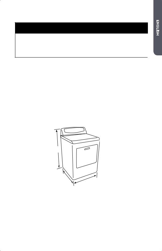
DRYER DIMENSIONS
42¹⁄ "
(108 CM)
28¹⁄ "
(72.4 CM) 27"
(68.6 CM)
7
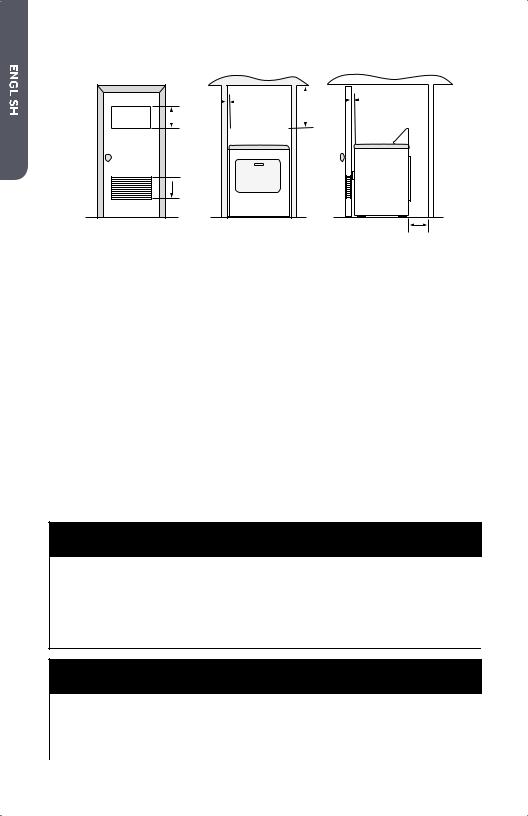
ALCOVE OR CLOSET REQUIREMENTS
|
1" |
|
|
|
|
|
|
1" |
||||||||||
|
|
|
15" |
|
|
|
|
(2.5 CM) |
||||||||||
|
|
|
|
|
|
|
||||||||||||
|
|
|
|
|
|
|
|
|
|
|
|
|
|
|
|
|||
|
|
|
(2.5 |
CM) |
||||||||||||||
|
|
|
|
60 IN.2 |
|
|
(38.1 |
CM) |
|
|
|
|||||||
|
|
|
|
|
|
|
|
|
||||||||||
|
|
|
|
(387.1 CM2) |
|
|
|
|
|
|
|
|
|
|||||
|
|
|
|
|
|
|
|
|
|
|
|
|
||||||
|
|
|
|
|
|
|
|
|
|
|
|
|
|
|
|
|
|
|
 60 IN.2 (387.1 CM2)
5½" (14 CM)
MINIMUM CLEARANCES
•Dimensions shown are the recommended minimum clearance allowances.
•Space on the sides of the dryer is required to avoid noise transfer.
•Space at the rear of the dryer is necessary to accommodate exhaust ducting.
OTHER REQUIREMENTS
•This dryer must be vented to the outdoors.
•Do not install the dryer in a closet with a solid door.
•A closet door must be louvered or vented with a minimum of 120 sq. in.
(774.2 sq. cm) of opening equally divided at the top and bottom of the door. The airßow must not be obstructed in any way.
•No other fuel-burning appliance shall be installed in the same closet as the gas dryer.
ELECTRICAL & GAS SUPPLY REQUIREMENTS
ELECTRIC DRYER (U.S. ONLY)
 WARNING
The dryer must be plugged into a properly grounded 3 or 4-wire, single phase, 120/240 volt (or 120/208 volt), 60Hz, AC-only electrical outlet connected to an individual 30-amp circuit, fused with a 30-amp time-delay fuse or circuit breaker. Do not operate a washer and dryer on the same circuit.
 WARNING
This appliance must be grounded. In the event of an electrical short circuit, grounding reduces the risk of electric shock by providing an escape route for the electrical current.
8

NOTE: The electrical supply for the dryer must conform with local codes and ordinances and the latest edition of the National Electrical Code, ANSI/NFPA 70.
•If the electrical supply available in the intended dryer location does not meet the above requirements, contact a licensed electrician.
•A dryer operating on a 208 volt power supply will have longer drying times than if it were operating on a 240 volt power supply.
•The dryer is not equipped with a power cord. A kit that meets local electrical codes must be purchased separately. The dryer can be Þtted with a 3 or 4-wire NEMA 14-30 or 10-30 type SRDT or ST (as required) power cord rated at 120/240 volt AC minimum, 30 amp, with 3 open-end spade lug connectors with upturned ends or closed loop connectors and marked for use with clothes dryers.
•A UL listed strain relief must be attached to the dryer to hold the power cord.
•Do not use an aluminum wire receptacle with copper-wired power cord and plug (or vice versa). The proper wiring and receptacle is a copper-wired power cord with a copper-wired receptacle.
•The electrical outlet should be located so that the power cord is accessible when the dryer is in the installed position.
ELECTRIC DRYER (CANADA ONLY)
 WARNING
The dryer must be plugged into a properly grounded 4-wire, single phase, 120/240 volt, 60Hz, AC-only electrical outlet connected to an individual 30-amp circuit, fused with a 30-amp time-delay fuse or circuit breaker. Do not operate a washer and dryer on the same circuit.
 WARNING
This appliance must be grounded. In the event of an electrical short circuit, grounding reduces the risk of electric shock by providing an escape route for the electrical current.
NOTE: The electrical service to the dryer must conform with local codes and ordinances and the latest edition of the CSA C22.1 Canadian Electrical Code Part 1.
•If the electrical supply available in the intended dryer location does not meet the above requirements, contact a licensed electrician.
•Do not use an aluminum wire receptacle with copper-wired power cord and plug (or vice versa). The proper wiring and receptacle is a copper-wired power cord with a copper-wired receptacle.
•The electrical outlet should be located so that the power cord is accessible when the dryer is in the installed position.
9
GAS DRYER
ELECTRICAL SUPPLY REQUIREMENTS
 WARNING
The gas dryer must be plugged into a properly grounded 3-wire, single phase, 120 volt, 60Hz, AC-only electrical outlet, fused with a 15-amp time-delay fuse or circuit breaker.
 WARNING
This appliance must be grounded. In the event of an electrical short circuit, grounding reduces the risk of electric shock by providing an escape route for the electrical current.
•The dryer is equipped with a power cord that has a 3 prong plug. Do not cut or remove the grounding prong from the power cord.
•The power cord must be plugged into a mating, 3 prong outlet, grounded in accordance with local codes and ordinances. If a mating outlet is not available, contacted a licensed electrician to have one installed.
•If you are not sure if your outlet is properly grounded, contact a licensed electrician.
•Do not use a 3 prong plug adapter.
•Do not use an extension cord.
GAS SUPPLY REQUIREMENTS
NOTE: The gas service to the dryer must conform with local codes and ordinances and the latest edition of the National Fuel Gas Code, ANSI Z223.1 or in Canada, CAN/CGA B149.1.
Natural Gas
•The dryer is equipped for use with Natural gas.
LP (Liquid Propane) Gas
•The dryer can be converted for use with LP gas.
•Conversion to LP gas must be made by a qualiÞed technician.
10
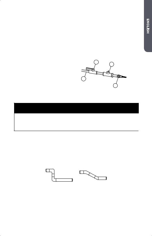
Gas Supply Line
•The gas supply line should be ½" (1.3 cm) pipe and must have an individual manual shut-o valve installed within 6 ft. (183 cm) of the dryer in accordance with the National Fuel Gas Code, ANSI Z223.1/NFPA 54, or in Canada with the Natural Gas and Propane Installation Code, B149.1.
•The shut-o valve should be easy to reach for opening and closing.
•A "" NPT minimum plugged tapping must be installed immediately upstream of the shut-o valve. This Þtting is used to check the gas pressure.
•The supply line should terminate with a !" NPT ßare adapter Þtting.
 ¹⁄ " NPT Gas Supply Line
 Gas Shut-O Valve
 ¹⁄ " NPT Minimum Plugged Tapping
 !" NPT Flare Adapter Fitting
B C
A
D
EXHAUST SYSTEM REQUIREMENTS
 WARNING
This section describes the requirements for a safe and e cient exhaust system. Failure to follow these instructions can result in poor dryer performance, damage to the dryer, and a Þre hazard.
DUCTING
•If your current exhaust system is constructed of plastic or metal foil ßexible ducting, replace it with rigid metal ducting.
•Use only 4” (10.2 cm) diameter rigid metal ducting.
•When making turns in the ductwork, use 45° elbows rather than 90° elbows. This provides better airßow and can reduce the accumulation of lint in the exhaust system.
90° - Good 45° - Better
11
•Do not exceed the length of duct pipe for the number of elbows shown in the chart below. Doing so can cause an accumulation of lint, increase drying time, and create a Þre hazard.
•Two 45° elbows equal one 90° elbow.
|
Recommended Maximum Exhaust Length |
||||||
|
|
|
|
|
|
|
|
|
Exhaust Hood Types |
||||||
|
|
|
|
|
|
|
|
|
Recommended |
|
|
|
Use Only For Short Run |
||
|
|
|
|
|
|
|
Installations |
|
|
|
|
|
|
|
|
|
4" |
|
|
|
|
|
4" |
|
(10.2 CM) |
|
|
|
|||
|
DIA. |
|
|
|
(10.2 CM) |
||
|
|
|
|
|
|
|
DIA. |
|
4" |
|
|
|
|
|
|
|
(10.2 CM) |
|
|
|
|
||
|
DIA. |
|
|
|
|
|
2½" |
|
|
|
|
|
|
|
|
|
|
4" |
|
|
|||
|
|
|
|
(6.4 CM) |
|||
|
(10.2 |
CM) |
|||||
|
|
||||||
|
|
|
|
|
|
|
|
No. of 90° Elbows |
Rigid Metal |
|
|
|
Rigid Metal |
||
|
|
|
|
|
|
|
|
0 |
90 feet |
|
|
|
60 feet |
||
1 |
60 feet |
|
|
|
45 feet |
||
2 |
45 feet |
|
|
|
35 feet |
||
3 |
35 feet |
|
|
|
25 feet |
||
|
|
|
|
|
|
|
|
•All joints should be tight to avoid air leaks. The male end of each section of ducting must point away from the dryer.
• Use clamps or duct tape to connect and seal all joints. Do not connect with screws or other fasteners that extend into the interior of the duct as they will create a collection point for lint.
Clamp
•Avoid running the exhaust system through an unheated area as this will cause condensation to form inside the duct and accelerate the rate of lint accumulation.
•Avoid running the exhaust system vertically through a roof as this may expose the exhaust system to down drafts, causing an increase in air restriction.
•Avoid sagging, compression or crimping of the exhaust system as this will result in reduced airßow and poor dryer performance.
•Do not screen the end of the exhaust system. Lint will accumulate and eventually clog the screen. Use an approved exhaust hood to terminate the duct outdoors.
12
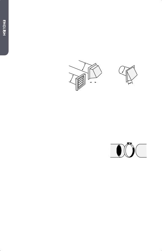
EXHAUST HOOD
•Use an approved exhaust hood with a swing-out damper that opens when the dryer is in operation. When the dryer stops, the damper automatically closes to prevent drafts and the entrance of insects and rodents.
•Louvered or box hood styles are recommended. Angled hood styles are acceptable, but should be used only for short run installations. See the “Recommended Maximum Exhaust Length” chart for more information.
•To avoid restricting air ßow, maintain a minimum of 12” (30.5 cm) clearance between the vent hood and the ground or any other obstruction.
MOBILE HOME - ADDITIONAL REQUIREMENTS
•The installation must conform to current Manufactured Home Construction and Safety Standard, Title 24 CFR-Part 3280 or the Canadian Manufactured Home Standard CAN/CSA-Z240 MH.
•Special provisions must be made for outside makeup air. The opening should be at least twice as large as the dryer exhaust outlet.
•If the dryer is exhausted through the ßoor and into an enclosed area beneath the mobile home, the exhaust system must terminate outside the enclosure with the termination securely fastened to the mobile home structure.
GAS DRYER ONLY (MOBILE HOME ONLY)
•The dryer must be fastened to the ßoor using a mobile home installation kit. Follow the instructions supplied with the kit.
13
STEP BY STEP INSTRUCTIONS
INSTALLING YOUR DRYER
We recommend that your new dryer be installed by a qualiÞed appliance technician. If you feel that you have the skills to install the dryer, please read the installation instructions carefully before installing.
CAUTION: If, after completing these steps, you are unsure that the dryer is properly installed, contact a qualiÞed appliance technician.
STEP 1 - UNPACK THE DRYER
1.Remove all packing materials. This includes the foam base and all adhesive tape holding the dryer accessories inside and outside.
2.Inspect and remove any remains of packing, tape or printed materials before using the dryer.
 WARNING
To avoid danger of su ocation, keep plastic bag and other packing material away from babies and children. Do not use this bag in cribs, carriages and playpens. The plastic bag could block nose and mouth and prevent breathing. This bag is not a toy.
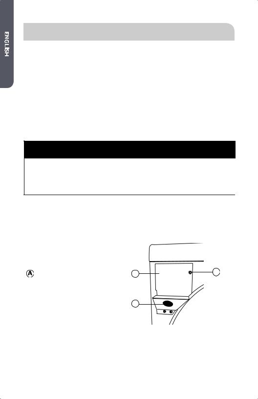
STEP 2 - ATTACH A POWER CORD TO THE DRYER (ELECTRIC DRYER - U.S. ONLY)
1.Remove the screw securing the terminal block access cover, located on the back of the dryer’s upper corner.
Terminal Block Access Cover |
A |
C |
 Hole in Strain Relief Mounting
Bracket
 Remove This Screw
B
14
2.Insert a UL listed strain relief into the mounting bracket hole. Position the strain relief so that one tab is pointing up and one tab is pointing down. Tighten the strain relief screws just enough to hold the two halves together.
Tab |
A |
Strain Relief |
B |
|
3.Insert a power cord into the strain relief. Take care to ensure that the wire insulation of the power cord is inside the strain relief.
4.Connect power cord wires following Part A for a 4-wire power cord connection or Part B for a 3-wire power cord connection.
4-wire (recommended) if your home has a 4-wire receptacle (NEMA 14-30 type SRDT or ST):
3-wire (if 4-wire is not available) if your home has a 3-wire receptacle (NEMA 10-30 type SRDT):
CAUTION: A 4-wire connection is required for mobile homes and where local codes do not permit the use of 3-wire connections.
5.Tighten strain relief screws.
6.Be sure that none of the wires are touching the dryer drum inside the dryer cabinet.
7.Reinstall the terminal block cover.
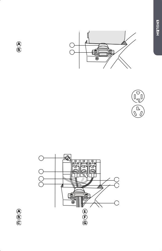
PART A - 4-WIRE POWER CORD |
|
A |
|
B |
|
C |
G |
D |
F |
|
E |
Green Ground Screw |
Power Cord |
Terminal Block Screw |
Green Power Cord Ground Wire |
Power Cord Wires (One Red; One |
Green (Neutral) Ground Wire From |
Black) |
the Dryer Harness |
 White (Neutral) Power Cord Wire
15
A1. Remove the green (neutral) ground wire from the green ground screw located above the terminal block.
A2. Attach the green power cord ground wire to the cabinet with the green ground screw. Tighten the screw securely.
A3. Attach the green (neutral) ground wire from the dryer harness and the white (neutral) power cord wire to the center terminal block screw. Tighten the screw securely.
A4. Attach each of the remaining 2 power cord wires (red and black) to one of the outer terminal block screws. Either wire can be attached to either screw. Tighten both screws securely.
IMPORTANT: Do not make a sharp bend or crimp the wires at connections.
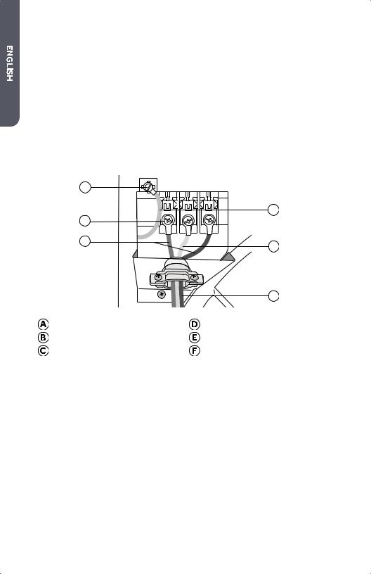
PART B - 3-WIRE POWER CORD
A |
|
|
F |
B |
|
C |
E |
|
|
D |
Green Ground Screw |
Power Cord |
Terminal Block Screw |
Center (Neutral) Power Cord Wire |
Outer Power Cord Wires |
Green (Neutral) Ground Wire |
|
From the Dryer Harness |
B1. Attach the center (neutral) power cord wire to the center terminal block screw. Tighten the screw securely.
B2. Attach each of the remaining 2 power cord wires to one of the outer terminal block screws. Either wire can be attached to either screw. Tighten both screws securely.
IMPORTANT: Do not make a sharp bend or crimp the wires at connections.
STEP 2 - CONNECT TO A GAS SUPPLY LINE (GAS DRYER ONLY)
NOTE: Do not connect the dryer to an LP gas line without Þrst converting the dyer with a conversion kit. An LP conversion kit must be installed by a qualiÞed technician.
NOTE: Apply a pipe-joint compound that that is resistant to the action of LP gas to all males threads. Do not use plumber’s tape.
16
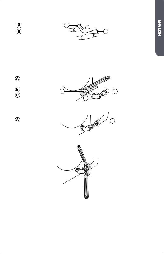
1. Turn the gas supply o by moving the shut-o valve to the closed position.
Closed Valve |
A |
|
|
Open Valve |
B |
2.Disconnect and discard old ßexible gas connector. Replace with a new CSA(AGA) approved ßexible gas connector.
3.Remove the shipping cap from the gas inlet pipe at the rear of the dryer.
4.Connect a !" NPT elbow to the gas inlet pipe on the dryer. Then connect a ßare adapter to the elbow.
IMPORTANT: Use a pipe wrench to keep the dryer gas inlet pipe from twisting.
Gas Inlet Pipe on |
|
|
the Dryer |
|
|
³⁄ " NPT Elbow |
A |
C |
³⁄ " NPT Flare Adapter |
|
B |
|
|
5. Connect the dryer to the gas supply line with a ßexible gas connector.
Flexible Gas Connector |
A |
6. Tighten the ßexible gas connector using two adjustable wrenches.
7. Turn the gas supply on by moving the shut-o valve to the open position. The valve is open when the handle is parallel to the gas pipe.
17
8. Check all connections for leaks by applying a noncorrosive leak-detection solution. Bubbles will identify leaks. If leaks are found, close the shut-o valve, retighten the joint, open the shut-o valve, and check again.
 WARNING
Never use an open .ame to test for gas leaks.
STEP 3 - CONNECT TO AN EXHAUST SYSTEM
 WARNING
To reduce the risk of Þre, this dryer must be exhausted outdoors.
1.Make sure that the exhaust system is free and clear of old lint accumulation prior to connecting the dryer.
2.Use 4” (102 mm) rigid or ßexible metal ducting to connect the dryer exhaust outlet to the exhaust system.
3.Use clamps to seal and secure all joints. Exhaust ducting must not be connected with screws or other fastening devices which extend into the interior of the duct.
NOTES:
•Do not use plastic or metal foil ßexible ducting. Excessive lint can build up inside the ductwork, restrict airßow, and create a Þre hazard. Restricted air ßow will increase drying time.
•The dryer must not be exhausted into a gas vent, chimney, wall, ceiling or other concealed space of a building. The dryer must be exhausted to the outdoors. If the dryer is not exhausted outdoors, some Þne lint will be expelled into the
laundry area. An accumulation of lint in any area of the home can create a health and Þre hazard.
18
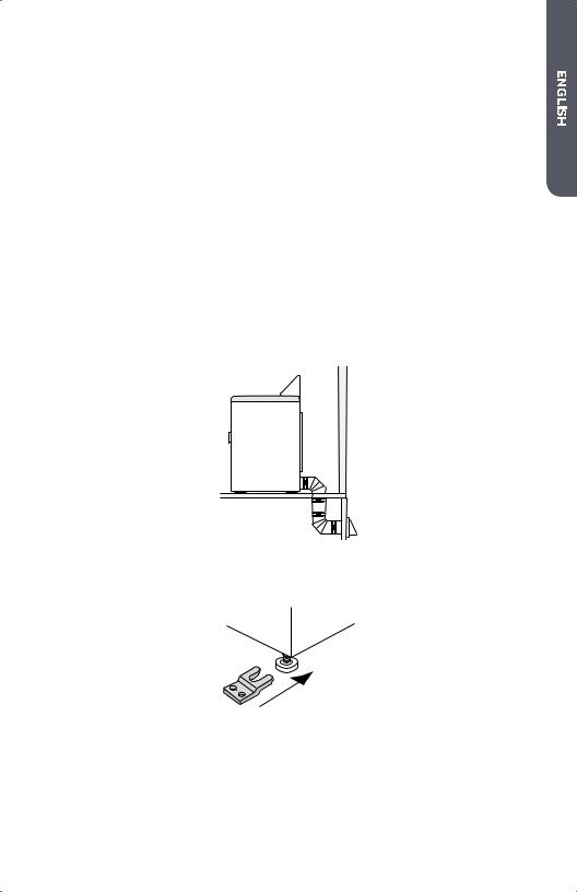
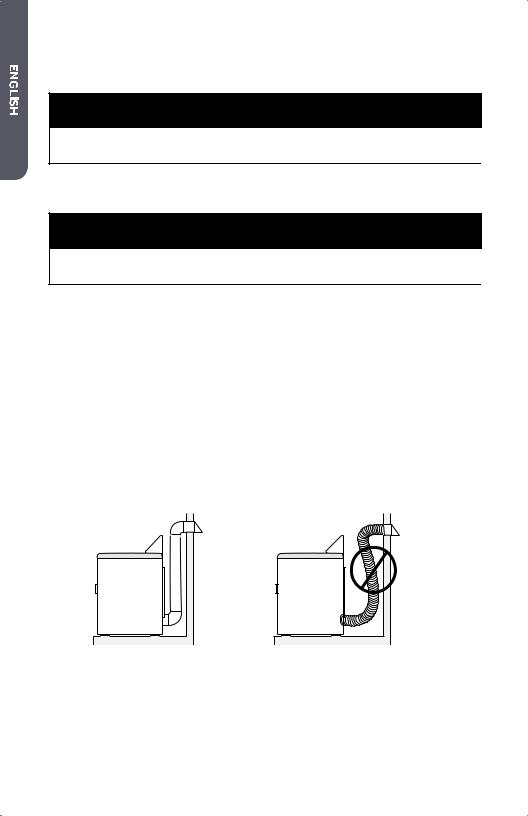
STEP 4 - LEVEL THE DRYER
1.Place the dryer in its Þnal location. Take care not to crush or kink the exhaust vent. Make sure that all four feet are Þrmly in contact with the ßoor and that the dryer rests solidly in position.
NOTE: For a gas dryer, make sure that there are no kinks in the ßexible gas line.
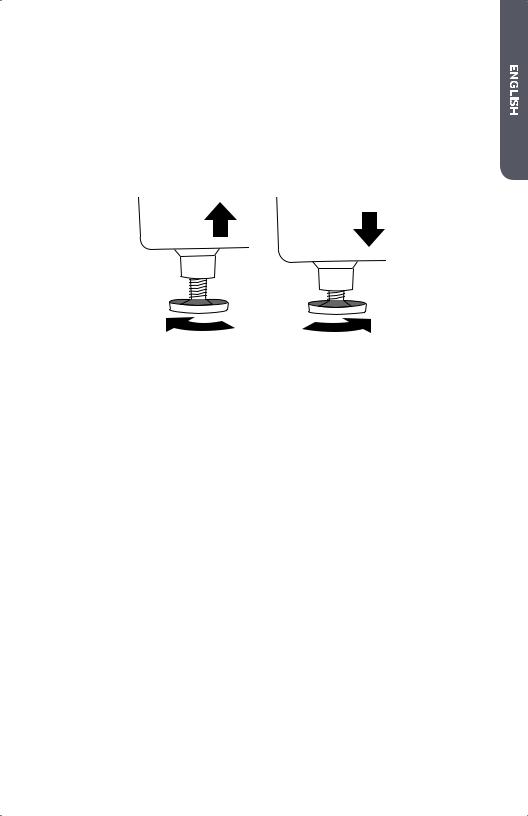
2.Using a carpenter’s level, check to make sure the dryer is level from side to side and from front to back.
3.If the dryer is not level, adjust the leveling feet. Turn clockwise to extend (raise the dryer) or counterclockwise to retract (lower the dryer).
STEP 5 - COMPLETE THE INSTALLATION
1.Plug the dryer power cord into an appropriate outlet.
2.Resume power to the outlet. Check to make sure the circuit breaker is switched on.
3.Dispose of/recycle all packaging materials.
4.Make sure the dryer area is clean and free from combustible materials, gasoline, and other ßammable vapors. Also see that nothing (such as boxes, clothing, etc.) obstructs the ßow of combustion and ventilation air through the louvered panel located on the rear of the dryer.
5.Test dryer operation by selecting a Timed Dry heated cycle. See the “Operating Instructions” section.
NOTE: On gas dryers, before the burner will light, it is necessary for the gas line to be bled of air. If the burner does not light within 45 seconds, the Þrst time the dryer is turned on, the safety switch will shut o the burner. If this happens, turn the dryer to “OFF” and wait 5 minutes before making another attempt to light the burner.
19
CONTROL PANEL AND FEATURES
CONTROL PANEL
Timed Dry |
Automatic |
120 min
90 min
Air Fluff
60 min
30 min
A B C D
 TEMP BUTTON
• Use to select a drying temperature. There are 4 available drying temperatures to choose from: High, Medium, Low, and Air Flu .
 CYCLE SELECTION KNOB
• Turn the dryer on by rotating the Cycle Selection Knob.
NOTE: If the dryer is not started, it will automatically turn o after 5 mins.
• There are 3 Automatic Cycles and 4 selections for Timed Dry:
Heavy Duty - Use this cycle for heavy garments like jeans and towels.
Normal - Use this cycle for permanent press, synthetics, casual clothes.
Delicate - Use this cycle to dry small loads and delicate fabrics.
Timed Dry - 30, 60, 90 or 120 minute cycles.
 START/PAUSE BUTTON
•Press this button to start a selected cycle or to pause an operating cycle.
NOTE: After starting the dryer, you must pause an operating cycle to change the Temp setting.
 CYCLE PROGRESS INDICATORS
•When the dryer is Þrst powered on, the Cycle Progress lights indicate all of the stages of the selected cycle.
•As a stage is completed, the light will turn o , indicating that the next stage is operating.
20

FEATURES
END OF CYCLE SIGNAL
•A signal will sound at the end of the cool down cycle to alert you that the load is complete.
WRINKLE SAVER
•At the end of the cool down cycle, the dryer will periodically tumble for 1 hour to prevent wrinkles from setting in your garments.
CYCLE GUIDE
NOTE: To protect your garments, all options and settings are not available for all cycles. The shaded boxes indicate the default settings for each cycle.
CYCLE |
FABRIC TYPE |
DRY PROCESS |
TEMPERATURE |
|
|
|
|
|
|
|
Heavily soiled, |
Heat |
High |
|
Automatic |
|
|||
|
||||
durable colorfast |
Cool Down |
|
||
Heavy Duty |
n/a |
|||
fabrics |
Wrinkle Saver |
|||
|
||||
|
|
|||
|
|
|
|
|
Automatic |
|
Heat |
High |
|
Cottons, linens, and |
|
|||
Cool Down |
Medium |
|||
Normal |
mixed garments |
|||
Wrinkle Saver |
||||
Low |
||||
|
|
|||
|
|
|
|
|
|
Lingerie, sheer |
Heat |
Low |
|
Automatic |
|
|||
|
||||
fabrics with lace |
Cool Down |
|
||
Delicate |
n/a |
|||
trim |
Wrinkle Saver |
|||
|
||||
|
|
|||
|
|
|
|
|
|
|
Heat |
Medium |
|
|
Cottons, linens, and |
|
||
Timed Dry |
High |
|||
Cool Down |
||||
mixed garments |
||||
Low |
||||
|
Wrinkle Saver |
|||
|
|
|||
|
|
Air Flu |
||
|
|
|
||
|
|
|
|
21
Status lights indicate the progress of an operating drying cycle.
OPERATING INSTRUCTIONS
STEP 1 - PREPARE AND SORT LAUNDRY
•Check garment labels for manufacturers’ drying instructions.
•Where possible, turn pockets inside out for uniform drying.
•Tie strings and sashes so they don’t tangle.
•Close zippers, snaps and hooks to avoid snagging.
•Make sure buttons and ornaments on the clothes are high temperature resistant and will not damage drum surface.
•To avoid permanently setting stains or soils, check that all stains and soils have been removed during the wash cycle. If not, wash them again.
•To avoid entanglement and ensure easy removal, small articles should be collected in a mesh bag before loading.
• Separate fabrics that attract lint from fabrics that give o lint. Clothes prone to linting should be turned inside out before being put into the dryer.
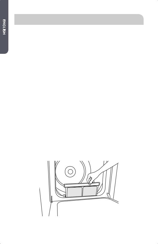
STEP 2 - CLEAN THE LINT SCREEN
1.Clean the lint screen before each use. The Þlter can be removed by pulling on the handle of the lint screen located inside the dryer door.
2. Use your Þngers to roll the accumulated lint o of the lint screen. Do not rinse or wash the lint screen to remove lint.
3. Slide the lint screen back into place.
NOTES:
•Do not operate the dryer without the lint screen in place. Without the screen, tumbling garments could enter the exhaust system and cause damage to the dryer.
•Lint buildup on the screen will restrict airßow and cause longer drying times.
22

STEP 3 - LOAD THE DRYER
1.Load damp garments loosely into the dryer drum.
2.Close the dryer door.
NOTES:
•Do not pack the dryer full of garments.
•An appropriate load should be 1/3 to 1/2 of the drum volume. Allow space for clothes to tumble freely for uniform and wrinkle-free drying.
•When drying large bulky items, only 2-3 pieces should be loaded at a time along with a few small and medium-sized garments.
•For delicate clothes or small loads, adding a couple towels will help to ensure that garments are tumbled. This will produce even drying and reduce wrinkles.
STEP 4 - START THE DRYER
1.Turn the dryer on by rotating the CYCLE SELECTION KNOB.
2.Select a dry cycle.
3.Modify the default settings and options if desired.
4.Press the START/PAUSE BUTTON on the face of the knob to start the dryer.
NOTE:
•Opening the door will pause the operating cycle. Close the door and press the START/PAUSE BUTTON to resume.
23

CARE AND CLEANING GUIDE
 WARNING
Always unplug your dryer to avoid electric shock before cleaning.
Ignoring this warning may result in death or injury.
Before using cleaning products, always read and follow manufacturer’s instructions and warnings to avoid personal injury or product damage.
CLEANING AND MAINTENANCE
•Only use a damp or sudsy cloth for cleaning the control panel.
•If you spill liquid/powdered softener, bleach or detergent on the cabinet, wipe the cabinet immediately to avoid damage to the Þnish.
•Do not use abrasive cleansers, harsh chemicals, ammonia, chlorine bleach, concentrated detergent, or solvents to clean the washer. These chemicals may dissolve, damage, or discolor the dryer.
•Do not use any type of spray cleaner when cleaning the dryer interior. Hazardous fumes or electric shock could occur. If dryer drum becomes stained, clean the drum with a damp cloth. Remove any residue before drying next load.
CLEANING THE LINT SCREEN
•Laundry detergent and fabric softener residue can build up on the lint screen. This buildup can cause longer drying times, or cause the dryer to stop before your load is completely dry.
•Wash the lint screen every 6 months, or sooner, if it becomes clogged due to a residue buildup.
Steps to Wash the Lint Screen:
1.Remove the normal accumulation of lint with your Þngers.
2.Wet both sides of lint screen with hot water.
3.Apply liquid detergent with water and scrub with a nylon brush.
4.Thoroughly rinse the lint screen with hot water.
5.Completely dry the lint screen before reinstalling and using the dryer.
24

REMOVING ACCUMULATED LINT
Inside the Dryer Cabinet
•Lint should be removed every 2 years, or more often, depending on dryer usage. Cleaning should be done by a qualiÞed person.
The Exhaust System
•The exhaust system should be inspected and cleaned at least every 12 months with normal usage. The more the dryer is used, the more often you should check the exhaust system and outdoor exhaust hood for proper operation.
VACATIONING PRECAUTIONS
•Unplug the dryer from the electrical outlet or disconnect the power.
•Clean lint screen. See the “Cleaning the Lint Screen” section.
• (For gas dryers only): Close shuto valve in gas supply line.
MOVING OR STORAGE PREPARATION
In addition to performing the steps in “Vacationing Precautions,” complete the following additional steps.
•Disconnect the dryer from the exhaust system.
•Turn the leveling feet so that they are fully retracted into the dryer cabinet.
•Use masking tape to secure dryer door.
•Move and store your dryer in an upright position only.
NOTE: For gas dryers, turn o the gas being supplied to the dryer. Disconnect the dryer from the gas supply line and remove Þttings attached to the dryer’s gas inlet pipe. Cap the gas supply line.
25

TROUBLESHOOTING
NORMAL OPERATING SOUNDS
•The following sounds are normal during the operation of the dryer.
•Tumbling sound: This is normal as the heavy, wet clothes in the dryer are continuously being tossed around.
•Air rushing noise: This happens as the dryer drum spins and the air is rushing through the dryer drum.
DRYER DOES NOT OPERATE
•Check that the dryer is plugged in. The plug may have come loose.
•Check that the electrical wall receptacle is of proper voltage. Electric dryers require a 240 volt power supply.
•Check if the circuit breaker needs to be reset, or if the fuse needs to be replaced.
•Check that the Cycle Select knob is in the “O ” position. Press the Start/Pause button again.
•Check that the dryer door is Þrmly shut.
CLOTHES ARE NOT DRYING
•Dryer may be overloaded. Wet clothes should not Þll more than ½ of the drum volume.
•Check the exhaust ducting and exhaust hood. The entire exhaust system should be free of obstructions.
•The exhaust system should be maintained, and cleaned regularly.
•Dryer load may need to be sorted. Heavyweight clothes should be separated from lightweight clothes.
•Bulky items may require repositioning.
•Check the lint screen. Lint screen should be cleaned before each load.
• Check that the dryer is not set on the Air Flu (no heat) temperature setting.
•For gas dryers, check that the gas supply line is open.
26
 Loading...