


YB500 OWNER’S MANUAL
HOW TO USE
YOUR GRUNDIG
YB500 AM/FM/SW Radio
NEED HELP? HERE’S HOW TO CONTACT US:
From the United States: 1-800-872-2228
From Canada: 1-800-637-1648
From everywhere else: 650-903-3866
e-mail: grundig@ix.netcom.com
World Wide Web: www.grundigradio.com
Eton Corporation/Grundig
1015 Corporation Way
Palo Alto, California 94303
United States
1
Contents |
|
Yacht Boy 500 - LC DATA MONITOR (Display)............................................................................................................. |
3 |
Your Unit at a Glance .......................................................................................................................................................... |
4 |
Aerials................................................................................................................................................................................................... |
6 |
Power Supply .............................................................................................................................................................................. |
7 |
AC (Mains) Operation ........................................................................................................................................................... |
7 |
Battery Operation................................................................................................................................................................... |
7 |
Battery Check .......................................................................................................................................................................... |
7 |
Data Protection........................................................................................................................................................................ |
8 |
Reset Button............................................................................................................................................................................. |
8 |
User Guide Via the Menu............................................................................................................................................................. |
9 |
General Operation ......................................................................................................................................................................... |
10 |
Key-protect............................................................................................................................................................................. |
10 |
LOCKED.................................................................................................................................................................................... |
10 |
Direct Entries ......................................................................................................................................................................... |
10 |
Hints and Error Messages ................................................................................................................................................. |
11 |
Display Illumination............................................................................................................................................................. |
12 |
The Volume............................................................................................................................................................................. |
12 |
The Tone.................................................................................................................................................................................. |
12 |
Waveband Selection............................................................................................................................................................ |
12 |
ROM Table of the Yacht Boy 500 ........................................................................................................................................ |
13 |
Selecting Frequencies......................................................................................................................................................... |
13 |
Calling Up ROM Table Memory Locations ............................................................................................................................. |
14 |
Step by Step into the World of Shortwave Reception ............................................................................................................. |
15 |
Tuning to Stations with the TUNE A/V buttons.................................................................................................................. |
16 |
Tuning to Stations......................................................................................................................................................................... |
17 |
Entering a Meter Band ................................................................................................................................................................. |
18 |
Storing in Memory General ......................................................................................................................................................... |
19 |
What can You Store?........................................................................................................................................................... |
19 |
Is the Frequency Tuned to Already Stored in Memory?........................................................................................ |
19 |
Checking the Desired Station Memory Position........................................................................................................ |
20 |
Programming a Station Memory Location................................................................................................................... |
20 |
Entering Abbreviations ....................................................................................................................................................... |
21 |
Calling Up Stored Stations................................................................................................................................................ |
21 |
The MEMORY Button ........................................................................................................................................................... |
22 |
Clearing an Occupied Memory Position........................................................................................................................ |
22 |
Going to Sleep to Radio .............................................................................................................................................................. |
23 |
The Clock........................................................................................................................................................................................... |
24 |
Setting the Clock .................................................................................................................................................................. |
24 |
Setting the Clock .................................................................................................................................................................. |
24 |
Clock Time Indication TIME I/II...................................................................................................................................... |
24 |
Automatic Functions Timer ½..................................................................................................................................................... |
25 |
Programming Switching Times Switching Times 1/2.............................................................................................. |
25 |
Checking the Switching Times 1 /2............................................................................................................................... |
26 |
Automatic Switching On and Off .................................................................................................................................... |
26 |
Automatic Functions.................................................................................................................................................................... |
27 |
Special Functions on FM ........................................................................................................................................................... |
28 |
Special Functions on AM .......................................................................................................................................................... |
29 |
2
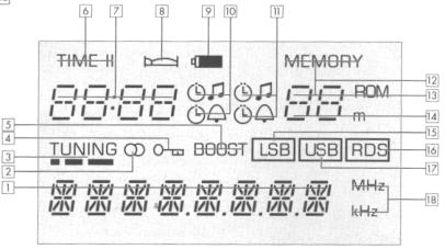
Yacht Boy 500 - LC DATA MONITOR (Display)
I n d i c a t i o n ( 1 ) - ( 1 8 )
1 8-digit alphanumeric display for
-Station name
Appears automatically when receiving an FM (VHF) station which is transmitting RDS (Radio Data System) signals. For other stations, you can enter a name of your choice.
-LW(Longwave), MW (Mediumwave), SW (Shortwave), and FM(VHF) : waveband, frequency.
-Programming functions
e.g., MENU , ON 1, OFF 1, etc.
-Hints (marked by )
e.g., LOCKED, ; NO RDS, Q - - (RDS quality), etc.
-Error messages (marked by ) e.g., e.g., MEMORY, FREQ, etc.
-Automatic switch-on times.
2 (FM stereo reception).
3TUNING (field strength indication)
4 (Key-protect= key locking).
5 BOOST (increased output power).
6 TIME I1/TIME II (related to the indication ).
7 - Clock times (TIME I/TIME II), SLEEP time (go-to-sleep time), alarm times.
8 
- one SLEEP time (go-to-sleep time) is programmed. - SNOOZE (alarm interrupt) is activated.
9  (battery check)
10Symbols for alarm modes (wake-up by radio programme or alarm sound signal alarm time 1).
11Symbols for alarm modes (wake-up by radio programme or alarm sound signal alarm time 2).
121 - 40 MEMORY (number of station memory location).
131 - 9 ROM (ROM table is selected).
14SW-Meter-Band
AS (AUTO SEARCH) = Automatic Station search.
0 |
= Tuning memory. |
AF |
= RDS Alternative Frequency. |
15 LSB (Lower Side Band):
Lower side bond on SSB reception. SSB = Single Side Band.
16 RDS (Radio Data System): You are receiving an FM station broadcasting RDS signals.
17USB(Upper Side Band)
Upper side band on SSB reception.
18MHz - kHz (frequency)
In MHz on FM (VHF), in kHz on AM (LW, MW, SW).
3
Your Unit at a Glance
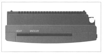
(1)Illumination Button (LIGHT)
-For switching on the display illumination on battery operation (permanent illumination on AC (mains) operation).
(2)SNOOZE Button
-To interrupt (press briefly) and switch off (longer pressure) the sound signal during the alarm function.
(3)Telescopic Aerial/Antenna
-For FM (VHF) and SW reception.
-Can be extended and swivelled.
(4)LC DATA MONITOR (Display)
(5)Numeric Buttons 0 ... 9
-For all numeric entries.
-Press 0/ROM button a longer time:
Passage from the ROM table to the normal memory level and back again, with tansfer into the tuning memory.
(6)MEMORY Button
-For calling up the station memory locations 1 ... 40 (enter with the numeric buttons 0 ... 9).
-For calling up the tuning memory 0.
-For calling up the ROM table 01 ... 09. Memory-Scan Press briefly: To step to higher memory location numbers;
Press a longer time: To step back to lower memory location numbers.
(7)Volume Control (VOLUME)
(8)CLEAR Button Press briefly:
-To clear wrong entries.
-To quit the menu functions.
-To abort entry of abbreviations. Press a very long time:
-To clear an occupied station memory location.
(9)Swing-out Support
in the rear of the unit.
- To bring the unit into a tilted position convenient for operation.
(10) Battery Compartment
in the rear of the unit.
(11)On/Off Button (ON/OFF)
combined with the locking switch (LOCK/UNLOCK).
(12)Fine Tuning Control (FINE TUNING)
for AM (MW, LW, SW) and SSB reception.
(13) (Key-protect = locks keys when unit is switched
on.)
-This prevents an indadvertent use of the function keys.
-Switching off is possible: set switch j to "LOCK".
(14)SLEEP Button (go-to-sleep button)
-For entering a period of time of up to 60 minutes in steps of 10 minutes, after which the radio switches off.
(15)FM/RDS-AF Button
-For selecting the FM (VHF) band.
You will hear the FM station last tuned to (Last Station Memory).
-For concluding a manual frequency entry.
-For calling up the AF = Alternative Frequencies which can be received via RDS (Radio Data System) when this band is already selected.
Press briefly = AF forward,
press a longer time = AF backward.
(16)TIME I/II
-To switch between time zone I and time zone II.
-To transfer a manually entered time into the actual time zone.
-To conclude a switching time I or II entry.
(17)AM Button
Press briefly:
- To select an AM band (LW, MW, SW).
Further pressures on this button will step through the AM bands in the order LW -* MW - SW -> LW -* MW, etc.
You will hear the station last tuned to in the respective AM band.
-For concluding a manual frequency entry.
-For concluding a manual band entry. Press a longer time
-On SW, stepping to the lower band limit of the following meter band as long as this button is kept pressed.
(18)AUTO Button
-For enabling and disabling the automatic functions after having set the alarm mode, the switching times and the station memory.
(19)TUNE /TUNE
On FM:
Press briefly:
-Frequency tuning in the 25 kHz mode. Press a longer time:
-Station search in the 100 kHz mode. TUNE = to higher frequencies. TUNE =to lower frequencies.
On MW and LW:
Press briefly:
-Frequency tuning in the 1 kHz mode. Press a longer time:
-Frequency tuning in the 9 kHz mode.
On MW, the Menu allows you to switch to the 10 kHz raster (USA mode).
Press a very long time:
Automatic frequency scan.
On SW:
Press briefly:
-Frequency tuning in the 1 kHz mode. Press a longer time:
-Frequency tuning within a meter band in the 5 kHz mode.
Press a very long time: Automatic frequency scan.
(20)MODE Button
Press briefly:
-To temporarily switch from name indication to frequency indication.
On SW, additional indication of the meter band. Press a longer time:
-To call up the menu.
(21)MONO/ROM-AF Button -
-Mono/stereo switching.
-To call up alternative frequencies with the "ROM table" selected.
4
(22)LSB/USB Button
-To select the lower or upper side band on SSB (Single iSide Band) reception.
Stepping button, steps forward in the order:
With reception frequency < 10 MHz = LSB Æ USB Æ Normal Æ LSB, etc.
With reception frequency ≥10 MHz = USB Æ LSB Æ Normal Æ USB, etc.
LSB= Lower Side Band; USB = Upper Side Band. On FM:
Keep pressed button = indication of the RDS quality
(23)STORE Button
-For storing the displayed frequency or the station name and the selected reception mode (e.g., Mc Stereo, LSB/USB) into one of the station memory locations 1 ...
40.
Press briefly: Store compare.
- Indication whether the frequency tuned to has ready been stored (e.g., MEMO 3 ... MEMO5 …
MEMO8 ... ).
-Further pressures on the button or keeping it press indicates whether the respective frequency is stored several times and, if so, on which location numbers.
-If the frequency is not yet stored, the display (4) indicate NEW.
Press a longer time:
-Indication of all free memory locations (e.g., FREE 6 ... FREE 8 ... FREE 25 ... ).
(24)A - Z Button
-To enter the abbreviation for the currently selected station memory location.
(25)SOUND (NORMAL -BOOST)
not on headphone operation. NORMAL = normal output power
(low-current drain on battery operation); BOOST= the output power is more than doubled(recommended on mains unit operation).
(26)TONE (MUSIC - SPEECH) MUSIC = normal reproduction; SPEECH = speech reproduction.
(27)Headphone Jack (Ω)
-For stereo headphones with 3.5 mm jack plug and an impedance of 32-2000Ω.
FM stereo reception is only possible with a headphone. When connecting a headphone, the built-in loudspeaker is automatically disconnected.
(28)3.5 mm Output Socket (LINE OUT)
-High-level output for making recordings.
(29)3.5 mm Output Switch Jack ( )
)
-For controlling external units (e.g., a tape deck).
(30)3.5 mm Coaxial Socket (DC IN 9V )
)
-For connecting the mains unit accompanying the unit (AC adapter NR 90-1).
5
Aerials
for all wavebands
Telescopic aerial(3)
for FM and SW reception.
•When the aerial base is completely pulled out, the telescopic aerial can be tilted and rotated into different positions.
•For SW reception, fully extend the aerial and place it vertically.
Due to the much more better propagation conditions during the evening and night hours, there may be interferences during these hours.
•These interferences can be reduced by partially pushing in the telescopic aerial.
Please note
Touching the telescopic antenna reduces FM and SW reception quality.
Ferrite aerial
for MW and LW reception (built-in).
• Turn the unit about its vertical axis to find the best reception position.
6
Power Supply
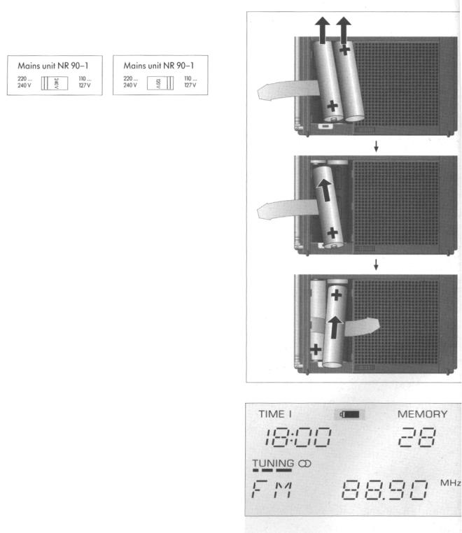
AC (Mains) Operation
•Only use the supplied AC (mains) unit NR 90-1 for the set.
•Adjust the local mains voltage on the AC (mains) unit.
220... |
240V |
110... |
127V |
•Connect the mains unit to the DC IN 9 V socket(30)
(30). This automatically disconnects the inserted batteries.
-No responsibility can be accepted for damage due to operation with the voltage selector set to the wrong position.
•Remove the batteries if the unit is to be operated permanently on the mains!
Battery Operation
With four 1.5 V batteries, type IEC LR 6 or AA.
We recommend the use of alkaline-manganese batteries with low mercury constituent or no mercury at all.
•Disconnect the plug of the AC (mains) unit from the DC IN 9 V socket (30).
•Open the cover of the battery compartment (10)
(on back of unit).
• Insert the batteries with correct polarity
(see scheme on bottom of battery compartment).
•For this, observe the order of the batteries and the position of the take-out ribbon (see Fig. to the right)
Battery Check
When the batteries get weak, a battery symbol ( ) will appear in the display (4).
7
Attention
•Remove exhausted batteries immediately from the unit!
•If the unit is not to be used for longer periods, remove batteries even if they are new!
-No responsibility can be accepted for damage due to leaking batteries.
Note on environmental protection
Do not throw exhausted batteries in the houshold waste ! Hand over the old batteries to your radio dealer or a public
collecting point when buying new ones.
Data Protection
(Mains and Battery Operation)
•When the power supply is disconnected, the time and the last station memory are retained for approx. 5 minutes.
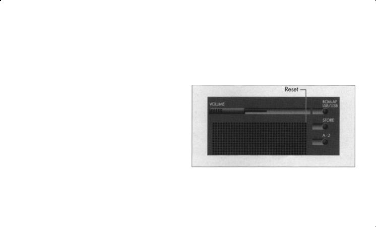
Reset Button
If, due to external interferences (caused by static charges of carpets, thunderstorms, etc.), the control electronics of your Yacht Boy 500 should receive wrong information signals, or if no entries at all are possible, then press the Reset button.
This is to be found behind the top right opening in the decorative speaker grill.
For pushing the switch, it is best to use a bent-up paper clip. By releasing the Reset impulse, the unit is reset to its initial programming state.
The contents of the individual station memory locations are not affected.
However the time setting and the contents of the last station memory will be cleared.
The stored stations and menu options will not be lost neither by a power supply failure nor by a Reset.
8

User Guide Via the Menu
With the unit switched on, call up the menu by pressing the MODE button (press a longer time).
Use the buttons TUNE and TUNE to select one after the other the different menu options:
Switch-on time ON 1- switch-off time OFF 1 -
Switch-on time ON 2 - switch-off time OFF 2 - iDisplay brightness - LAMP 0 ... 4 -
Sound signal intensity BEEP 0 ...4 -
MW raster frequency 9 kHz or 10 kHz.
You can quit the menu ...
-by pressing the CLEAR button,
-automatically 60 seconds after completion of the 1 entry,
-by pressing the MODE button when the display sho,
MENU .
9
 Loading...