


Assembly Instructions |
|
English |
Grundig SAT SystEms
Head-End Digital Modulator
HDM 2370 P CI
|
|
|
KLASSE A |
|
|
|
|
||
|
|
|
|
|
|||||
|
|
|
|
|
CLASS |
|
|
|
|
|
|
|
|
|
|
|
|
|
|
|
|
|
|
|
|
|
|
|
|
GSS |
Phone: |
+49 (0) 911 / 703 8877 |
|||||||
Grundig SAT Systems GmbH |
Fax: |
+49 (0) 911 / 703 9210 |
|||||||
Beuthener Straße 43 |
E-mail: |
info@gss.tv |
|||||||
D-90471 Nuremberg |
Internet: |
http://www.gss.tv |
|||||||

Contents
1 |
Safety regulations..................................................................................................... |
4 |
|
2 General information ................................................................................................. |
4 |
||
|
2.1 |
Packing contents ....................................................................................... |
4 |
|
2.2 |
Meaning of the symbols used ..................................................................... |
5 |
|
2.3 |
Technical data .......................................................................................... |
5 |
|
2.4 |
Description............................................................................................... |
6 |
|
2.5 |
Software query ......................................................................................... |
7 |
3 Assembly ................................................................................................................. |
7 |
||
|
3.1 |
Installing the cassette ................................................................................. |
7 |
|
3.2 |
Installing the F terminals............................................................................. |
8 |
|
3.3 |
Connecting the cassette ............................................................................. |
8 |
|
3.4 |
Retrofitting a CA module............................................................................ |
9 |
4 |
The control panel at a glance .................................................................................. |
10 |
|
|
4.1 |
Menu items ............................................................................................ |
10 |
|
4.2 |
Control panel ......................................................................................... |
10 |
5 Programming ......................................................................................................... |
11 |
||
|
5.1 |
Preparation ............................................................................................ |
11 |
|
5.2 |
Notes on the following programming procedure ......................................... |
11 |
|
5.3 |
Programming procedure .......................................................................... |
12 |
|
|
5.3.1 Decoding 2 stations with one CA module (channel strip “B”)............. |
15 |
|
|
5.3.2 Time controlled switching.............................................................. |
16 |
|
5.4 |
Programming the cassette ........................................................................ |
17 |
|
|
Selecting the cassette............................................................................... |
17 |
|
|
5.4.1 Programming the main menu of the cassette.................................... |
18 |
|
|
Querying the software version....................................................... |
18 |
|
|
Selecting the channel strips “A”/“B” and ”a“/“b“ ........................... |
18 |
|
|
Setting time-controlled, alternative channels .................................... |
19 |
|
|
Decoding of two channels with one CA module............................... |
19 |
|
|
Modulator operating mode ........................................................... |
19 |
|
|
Adjusting the output levels of the channel strips ............................... |
19 |
|
|
Setting the TV standard of the output signal .................................... |
20 |
|
|
Setting the output channel / output frequency.................................. |
20 |
|
|
Setting the fine-tuning ................................................................... |
21 |
|
|
Settings for TV stations.................................................................. |
21 |
|
|
Setting the LNB oscillator frequency ............................................... |
21 |
|
|
Setting the input symbol rate ......................................................... |
22 |
|
|
Configuring the CA module .......................................................... |
22 |
|
|
Setting the input frequency............................................................ |
22 |
|
|
Reception quality ......................................................................... |
23 |
|
|
Channel selection ........................................................................ |
24 |
|
|
Selecting the TV station sound ....................................................... |
25 |
|
|
Setting the volume level ................................................................ |
26 |
|
|
Setting the time zone and summer time........................................... |
26 |
|
|
Saving settings ............................................................................ |
27 |
|
|
|
|
|
|
- 2 - |
|
|
|
|
|

5.4.1.1 Adjusting the output levels of the channel strips................... |
28 |
5.4.1.2 Settings for TV stations..................................................... |
29 |
Automatic picture format conversion.................................. |
29 |
Adjusting the picture format.............................................. |
30 |
Locking the regional window............................................ |
30 |
Switching teletext mode off/on ......................................... |
31 |
Activating and entering teletext subtitle pages..................... |
31 |
Setting the teletext standard.............................................. |
32 |
Setting audio output ........................................................ |
32 |
Setting the audio mode.................................................... |
33 |
5.4.1.3 Configuring the CA module.............................................. |
33 |
5.4.2 Decoding 2 stations with one CA module ....................................... |
34 |
Selecting the channel strip ............................................................ |
35 |
Modulator operating mode........................................................... |
35 |
Setting the TV standard of the output signal .................................... |
35 |
Setting the output channel / output frequency ................................. |
35 |
Setting the LNB oscillator frequency ............................................... |
35 |
Switching on decoding / Setting the input symbol rate..................... |
36 |
Switch off decoding..................................................................... |
37 |
5.4.3 Setting time-controlled, alternative channels .................................... |
38 |
Switching the timer on and off ...................................................... |
38 |
Setting the switch-on time ............................................................ |
38 |
Setting the switch-off time ............................................................. |
39 |
Setting the days of the week ......................................................... |
39 |
6 Channel and frequency tables ................................................................................. |
40 |
- 3 -
1 Safety regulations
Warning
•Assembly, installation and servicing should be carried out by authorised electricians.
•Switch off the operating voltage of the system before beginning with assembly or service work or pull out the mains plug.
•Do not perform installation and service work during thunderstorms.
•Install the system so it will not be able to vibrate…
-in a dust-free, dry environment
-in such a manner that it is protected from moisture, fumes, splashing water and dampness
-somewhere protected from direct sunlight
-not within the immediate vicinity of heat sources
-in an ambient temperature of -20 °C to +50 °C.
•Ensure that the head-end station is adequately ventilated. Do not cover the ventilation slots.
•Beware of short circuits
•No liability is accepted for any damage caused by faulty connections or inappropriate handling.
•Observe the relevant standards, regulations and guidelines on the installation and operation of antenna systems.
•Earth the SAT receiver in accordance with DIN EN 50083-1 / EN 60728-11 and VDE 0855 (earthed, equipotential bonding rail).
Take action to prevent static discharge when working on the device.
2 General information
2.1 Packing contents
1 cassette HDM 2370 P CI
2 HF cables
1 CD (assembly instructions)
1 Brief assembly instructions
- 4 -

2.2 Meaning of the symbols used
|
Important note |
—> |
General note |
• |
Performing works |
2.3Technical data
The devices meet the following EU directives:
2006/95/EC, 2004/108/EC
The product fulfils the guidelines and standards for CE labelling.
HF input |
|
Frequency range: |
950 … 2150 MHz |
Level range: |
60 dBµV … 80 dBµV |
Input norm: |
QPSK |
Symbol rate: |
2 … 40 Msymb./s, SCPC/MCPC |
FEC: |
automatic |
HF output |
|
Channels: |
C2 … C69 (incl. S2 … S41) |
Frequency range: |
48.25 MHz … 855.25 MHz |
Standard: |
CCIR PAL B/G |
|
PAL I (GB 6.0 FM) |
Output level: |
typ. 95 dBµV |
Output impedance: |
75 Ω |
Frequency detuning of the output signal: |
|
|
±4.00 MHz in 62.5 kHz increments |
MPEG decoding |
|
MPEG 2: |
Main Level/Main Profile |
Video output: |
720 x 576 x 25 (Pixels x lines x Frames/sec) |
Audio: |
32 kHz, 44.1 kHz, 48 kHz |
Picture format: |
options for letterbox, 16:9 |
Teletext capable: |
yes |
VPS capable: |
yes (teletext, EIT) |
- 5 -

Connections |
|
|
SAT inputs A and B: |
2 |
F sockets |
HF output (modulators): |
1 |
IEC socket |
Connection strip (10-pin): |
for supply voltages and control circuits |
|
Socket RS 232: |
serial interface for software update |
|
Conditional access: |
2 channels can be decoded |
|
2.4Description
The twin transmodulator cassette is a QPSK-converter, which converts all stations modulated according to DVB-S1 standard and QPSK2 into two PAL-modu- lated cable signals. The cassette has two digital SAT IF inputs and an HF output. It is equipped with two channel strips (“A” and “B”). Each channel strip consists of a digital tuner, a digital signal preparation unit and a modulator.
The channel strip “A” can decode encoded channels via a corresponding CA module. Depending on the CA module and the smart card, two channels can be decoded simultaneously with one CA module, with the second one supplied via channel strip “B”. The control of the cassette takes place via the control unit of the head-end station. By means of the “a” and “b” levels of the channel strips, channel selection according to a timer is possible. The cassette‘s channel strips are indicated by “Bx A / Bx a“ or “Bx B / Bx b” (“Bx a” / “Bx b” – time controlled channel switch over) in the control unit display.
The prepared input signals reach the HF output collector of the head-end station via the HF output socket. The common output level of the channel strips can be set with the level regulator at the output collector of the head-end station.
When the head-end station is switched on, the two-line LC display briefly shows the software version of the control unit.
To operate this cassette the software version of the control unit must be “V 37” or higher. You can find the current operating software for the control unit and the cassette, the software “BE-Flash” and the current assembly instructions on the website “www.gss.tv”.
The cassette is designed for use in the following head-end stations:
–STC 316
–STC 1200
–STR 19-8
1DVB-S – Digital Video Broadcasting - Satellite
2QPSK – Quadrature Phase Shift Keying
-6 -

2.5Software query
Control unit
If necessary, you can activate the indication of the software version of the control unit manually:
•Press any two keys on the control unit of the head-end station simultaneously until the display goes dark and the software version, e.g. “V 37” appears.
3 Assembly
3.1 Installing the cassette
Caution
– Ensure the head-end station is mounted so it will not be able to vibrate. Avoid, for example, mounting the head-end station onto a lift shaft or any other wall or floor construction that vibrates in a similar way.
–Before installing or changing a cassette unplug the power cable from the mains power socket.
•Remove the fastening screws 1 of an unoccupied slot from the bracket of the head-end station.
•Insert the cassette in this slot and push it into the housing.
•Align the cassette and apply slight pressure to connect it to the connections of the board and the HF bus bar.
•Fasten the cassette with the 1 screws.
|
|
|
|
|
|
C101 |
|
|
|
|
L104 |
|
|
|
L100 |
|
|
|
L101 |
|
|
|
L103 |
|
|
C100 |
|
|
|
LNC- |
BREITBA |
|
|
+18V |
+24 |
|
|
ROT |
GRUEN |
|
|
+18V |
|
|
|
Anschl. |
|
|
|
|
|
INPUT |
OUTPUT |
OUTPUT |
INPUT |
- 7 -
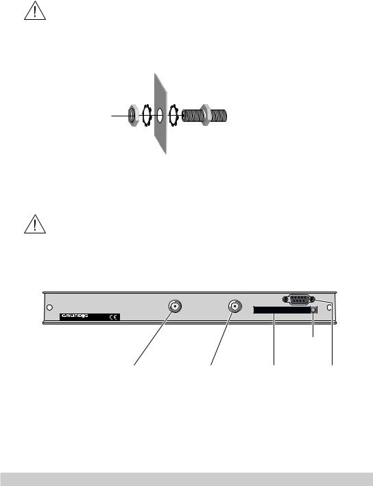
3.2 Installing the F terminals
To comply with the current EMC regulations, it is necessary to connect the lines leading in and out of the head-end station using F terminals.
When mounting the cassette in an STR 19-8 head-end station which is installed in a 19" cabinet, make sure the connections leading in and out for the 19" cabinet are made using F terminals.
•Insert the required number of F terminals in the openings provided in the head-end station or in the 19" cabinet.
—> F terminals are not included in the scope of delivery.
Tighten the nut on the F terminal until the teeth on the lock washer have penetrated the exterior coating and a good connection is made between the housing and F terminal.
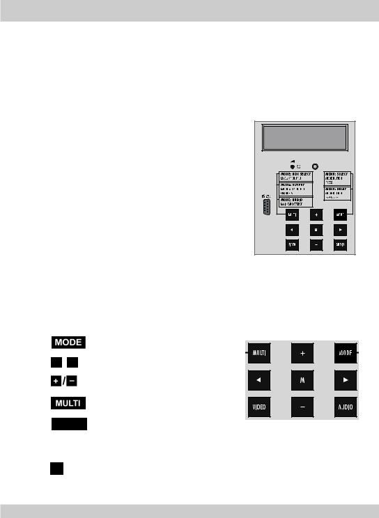
3.3 Connecting the cassette
Eject button for CA module
HF input "B" |
HF input "A" |
Slot for |
RS 232 |
|
|
CA module |
|
•Plug the HF input cables into the HF input sockets “HF input A” 2 (channel strip “A”) and “HF input B” 1 (channel strip “B”).
•Connect the head-end station to the mains power supply.
-8 -

Notes:
3 Slot for CA module
4 Eject button for CA module
5Socket “RS 232”
The operating software of the cassette can be updated via the 9-Pin D-DUB socket “RS 232” using a PC or notebook and the software “BE-Flash”. You can find the current operating software on the website “www.gss.tv”.
3.4Retrofitting a CA module
The cassette is equipped with a common interface. It allows you to connect a CA module for various encryption systems and service providers. Encoded channels can only be decoded with a CA module suitable for the encoding system and the corresponding smart card. The smart card contains all the information for authorisation, decoding and subscription.
Caution
– Check with the distributor or manufacturer of the CA module to be used to ensure that it is suitable for decoding 2 channels.
–The hardware and software of this cassette have been thoroughly prepared and tested.
–Any changes made by program vendors to the structures in the program data might impair or even prevent this function.
–When working with the CA module, please read the corresponding operating manual from the respective provider.
•Insert the smart card into the CA module so that the chip on the smart card faces the thicker side (top) of the CA module.
•Insert the CA module into the slot 3 (s. chap. 3.3) with the top side of the CA module facing the top side of the cassette.
•Push the CA module without canting into the guide rails of the common interface slot and contact it to the common interface.
•To take out the CA module press the eject button 4.
- 9 -
4 The control panel at a glance
4.1Menu items
Program the cassette using the buttons on the control unit of the head-end station. The two-line display of the control unit then shows the menus.
Use the  key to select the following main menu items:
–Cassette
–Channel strip, software
–Modulator settings
–TV standard
–Output channel / output frequency
–LNB oscillator frequency
–Input symbol rate
–Input frequency
–Channel selection
–TV station sound
–Volume
–Time zone and summer time
BE–Remote |
V 37 |
please wait . . . |
|
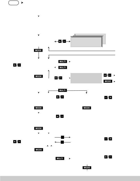
4.2 Control panel
The key pad on the head-end station is used to scroll through the menus and menu items one at a time:
/
VIDEO
M
scrolls forward through the menu.
select parameters in the menus.
set values, initiate actions
selects sub-menus
switches over between the
“Setting the input frequency” and the “Channel selection” menus.
saves all entries.
- 10 -
5 Programming
5.1Preparation
•Connect the test receiver to the HF output or the test output of the head-end station.
•Set the output channel / output frequency of the cassette (see page 20) and adjust the TV test receiver to this channel.
•Switch on the modulator if necessary.
•Balance the output levels of the channel strips “A” and “B” if the difference in level is ≥ 1 dB (see chapter “Modulator settings”, page 19).
•Measure the output levels of the analogue cassettes and tune them to a uniform output level using the appropriate level controls 2 (s. page 7).
5.2Notes on the following programming procedure
–The parameters to be set are underlined (cursor).
–Connection C : Time-controlled channel selection
–Connection D : Decoding 2 stations with one CA module
- 11 -
5.3 Programming procedure
Ein / On |
|
|
BE–Remote |
V 37 |
|
|
|
|
|
|
|
||||||
|
|
please wait … |
|
|
|
|
|
|
|
|
|||||||
|
|
|
|
|
|
|
|
|
|||||||||
|
|
|
|
|
|
|
|
|
|
|
|||||||
|
|
|
|
|
|
|
|
|
|
|
|
|
|
|
|
||
|
|
|
|
|
t > 10 s |
|
|
|
|
|
|
|
|
|
|||
|
|
|
|
|
|
|
|
|
|
|
|
|
|
|
|
|
|
|
|
|
|
|
|
|
|
|
|
|
|
|
|
|
|
|
|
|
|
|
|
|
|
|
|
|
|
|
|
|
|
|
|
|
|
|
|
|
Bx 1A |
|
|
TWIN-SAT |
|
|
|
|
|
|
|
||||
|
|
|
C5-12,S3-24 |
C07 |
|
|
|
|
|
|
|
||||||
|
|
|
|
|
|
|
|
|
|
|
|
|
|
|
|
|
|
|
|
|
|
|
|
+ |
|
|
|
|
|
|
|
|
|
|
|
|
|
|
|
|
|
|
|
|
|
|
|
|
|
|
|
|
|
|
|
|
|
|
|
|
|
|
|
|
|
Bx 1A |
TWIN-SAT |
|
|
|
|
|
|
|
Box 4 |
|
|
QPSK-PAL |
|
Böx 4 |
TWIN-SAT |
|
|
|
|||||
|
|
|
|
|
|
Bx 5A |
DVBT-DVBT |
|
|
|
|||||||
|
|
|
|
|
|
|
|
|
|
|
|
C5-12,S3-24 |
C07 |
|
|
|
|
|
|
|
C2-69,S2-41 |
– – – |
|
C5-12,S3-24 |
C07 |
|
|
|
|||||||
|
|
|
|
BD3 |
|
C09 |
|
|
|
||||||||
|
|
|
|
|
|
|
|
|
|
|
|
|
|
|
|
|
|
|
|
|
|
|
|
|
|
|
|
|
|
|
|
|
|
|
|
|
|
|
|
|
|
|
|
|
|
|
|
Page 14 |
A / B |
|
|
|
|
|
|
|
|
|
|
|
|
Bx 4A |
|
QPSK-PAL |
|
|
|
Bx 4A |
VERSION: |
|
|
|||
|
|
|
|
|
|
|||||||
|
Das Erste |
S21 |
|
|
|
DVB-PAL |
B V.16 |
|
Page 16 |
|||
|
|
|
|
|
|
|
|
|
|
|
|
|
|
|
|
|
|
|
|
|
|
|
|
|
|
|
|
|
|
|
|
|
|
|
Bx 4B |
QPSK-PAL |
|
|
|
|
|
|
|
|
|
|
|
||||
|
|
|
|
|
|
|
|
|
SAT.1 |
S09 |
|
Page 15 |
|
|
|
|
|
|
|
|
|
|
|||
|
|
|
|
|
|
|
|
|
|
|
|
|
|
|
|
|
|
|
|
|
|
|
|
|
|
|
|
|
|
|
|
|
|
|
|
|
|
|
|
Bx 4A |
|
|
OUTPUT: |
|
|
|
Bx 4A |
OUTPUT: |
|
|
|
|
Modulator: |
|
on |
|
on / off |
|
HF-Level: |
0 |
0 … –7 dB |
|||
|
|
|
|
|
|
|
|
|
|
|
|
|
|
|
|
|
|
|
|
|
|
|
|
|
|
|
Bx 4A |
|
|
NORM: |
|
|
|
|
|
|
|
|
|
CCIR |
5.5 |
FM |
|
CCIR 5.5 FM / GB 6.0 FM |
|
|
|
||||
|
|
|
|
|
|
|
|
|||||
|
|
|
|
|
|
|
|
|
|
|
|
|
|
|
|
|
|
|
|
|
|
|
|
|
|
|
Bx 4A |
OUTPUT: |
|
|
||
|
S21 |
|
|
|
|
|
|
|
|
|
|
|
|
|
|
|
|
|
|
|
|
|
|
|
|
|
|
|
Bx 4A |
OUTPUT: |
|
|
|
S21 |
Fine |
0 |
–64 … +63 |
|
|
|
|
|
|
Bx 4A |
VIDEO-OUT: |
|
|
|
Letter |
|
|
Letter / 16:9 |
|
|
|
|
|
- 12 -
 Loading...