


Part #455308
Centrifugal Utility Fans
Model SWB - Series 100, 200 and 300
Models SFB and SFD
Installation, Operation and Maintenance Manual
Please read and save these instructions for future reference.. Read carefully before attempting to assemble, install, operate or maintain the product described. . Protect yourself and others by observing all safety information.. Failure to comply with instructions could result in personal injury and/or property damage!
Model SWB |
Model SWB |
Model SWB |
Series 300 |
Series 200 |
Series 100 |
Model SFB
Table of Contents |
|
Motor and Drive Installation |
|
(Units Shipped from Stock). . . . . . . . . . . . . . . . |
2 |
Installation.. . . . . . . . . . . . . . . . . . . . . . . . . . . . . . . |
3 |
Affect of Installation on Performance . . . . . . . . . |
. 3 |
UL/cUL 762 - Restaurant Exhaust.. . . . . . . . . . . . |
4 |
Pre-Starting Checks. . . . . . . . . . . . . . . . . . . . . . . |
4-5 |
Belt Drive Fan Maintenance.. . . . . . . . . . . . . . . . . |
6 |
Bearing Lubrication Schedule . . . . . . . . . . . . . . . |
. 6 |
Motor Maintenance (Belt and Direct Drive). . . . . |
6 |
Parts List.. . . . . . . . . . . . . . . . . . . . . . . . . . . . . . . . |
7 |
Troubleshooting Chart . . . . . . . . . . . . . . . . . . . . . . 8
Model SFD
Centrifugal Utility Fans 1

Motor and Drive Installation Instructions
Model SWB units are shipped from stock without motors or drives..
1.Adjust motor pulley to its closed position for maximum fan speed or increments of 1/2 turn open (maximum of 5 turns open) for reduced fan speed.. Tighten set screw on flat area only..
4. Install shaft pulley to fan shaft..
2.Install motor pulley to the motor shaft and install motor to the motor plate.. Pre-punched holes are provided for most common motor frame sizes..
5.Install drive belt(s).. Belts should not be forced over pulleys.. Align motor and shaft pulleys with a straight edge.. Tighten all set screws..
3.If supplied, install taperlock bushing into shaft pulley..
6.Adjust belt tension..
See page 6 for belt tensioning instructions..
2 Centrifugal Utility Fans
®
Installation
Inspect the unit for any damage and report it to the shipper immediately.. Also, check to see that all accessory items are accounted for..
Move the fan to the desired location and fasten securely through mounting holes provided in the base angles.. The unit must be set level (shimming may be necessary).. Flexible duct connections and vibration isolators should be used where noise is a factor..
The motor voltage and ampere rating must be checked for compatibility with the electrical supply prior to final electrical connection.. Supply wiring to the fan must be properly fused, and conform to local and national electrical codes..
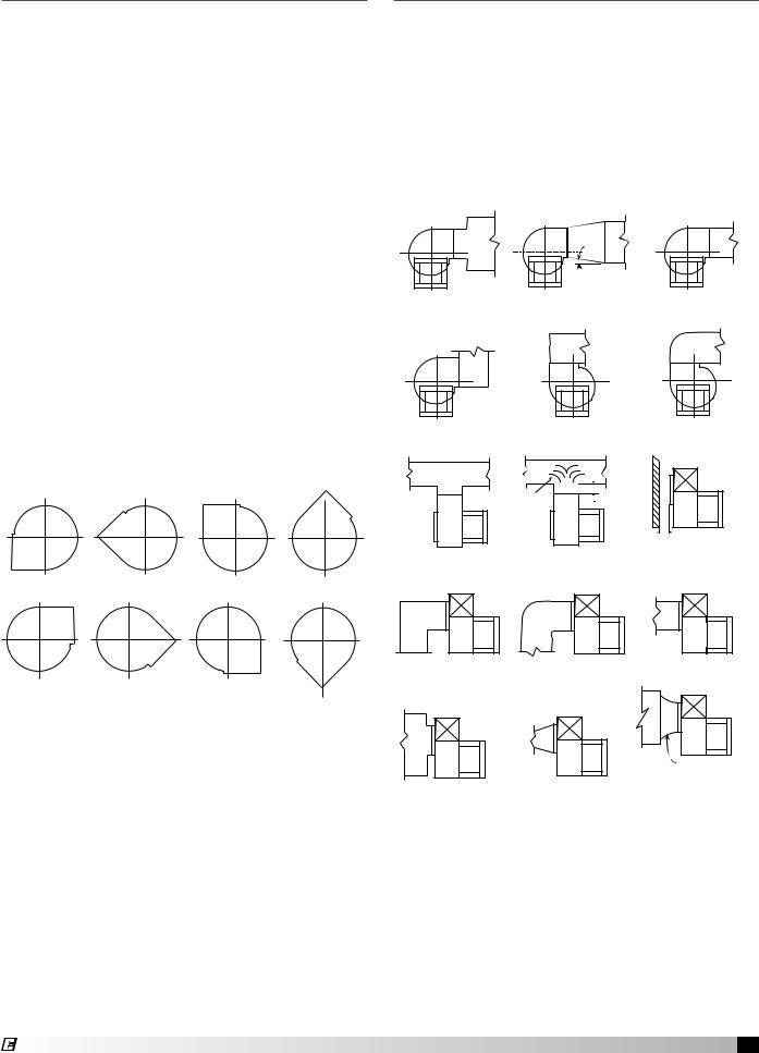
The discharge is factory set as specified by customer order, however, it can be rotated to other discharge positions in the field if necessary.. Removal of the housing bolts allows the discharge to be rotated to the clockwise positions below.. For TAD, BD and BAD discharge positions, a portion of the frame angle must be removed..
Clockwise rotation shown.. Counterclockwise discharge positions are a mirror image of those shown.. Fan rotation is always specified from the drive side of the housing..
Discharge Positions
CW BH |
CW BAU |
CW UB |
CW TAU |
CW TH |
CW TAD |
CW DB |
CW BAD
®
Affect of Installation on Performance
Restricted or unstable flow at the fan inlet can cause pre-rotation of incoming air or uneven loading of the fan wheel, yielding large system losses, increased sound levels and structural failure of the fan wheel.. Free discharge or turbulent flow in the discharge ductwork will also result in system effect losses..
The examples below show the system layout and inlet and discharge configurations which can affect fan performance..
Discharge Configurations
 7o MAX.
POOR |
FAIR |
GOOD |
POOR |
POOR |
FAIR |
|
Turning |
One |
|
Impeller |
|
|
Varies |
|
|
Dia. |
|
|
|
|
|
|
Should be at least |
|
|
1/2 Impeller Dia. |
POOR |
FAIR |
GOOD |
POOR |
FAIR |
GOOD |
Not Greater than 60o Including Angle
POOR |
POOR |
FAIR |
Centrifugal Utility Fans 3
 Loading...