


PN 457691
 ®
® 


 Models CW/CWB
Centrifugal Sidewall Exhaust Fans
Installation, Operation and Maintenance Manual
Please read and save these instructions for future reference. Read carefully before attempting to assemble, install, operate or maintain the product described. Protect yourself and others by observing all safety information. Failure to comply with instructions could result in personal injury and/or property damage!
Model CW
Direct Drive
Model CW |
is a |
direct |
drive |
centrifugal |
sidewall |
exhaust |
fan. |
These fans are specifically designed for wall mounted application. Performance capabilities range up to 6,400 cfm (10,874 m3/hr) and up to 3 in. wg (747 Pa) of static pressure. The maximum continuous operating
temperature for fan sizes 098-200 is 400°F (204°C) and for fan sizes 060-095 is 160°F (71°C). CW fans are available in fourteen sizes with nominal wheel diameter ranging from 9 to 20 inches (229 mm to 508 mm) (060 - 200 unit sizes). Each fan shall bear a permanently affixed manufacturer’s engraved metal nameplate containing the model number and individual serial number.
Model CWB
Belt Drive
Model CWB is a belt drive centrifugal sidewall exhaust fan. These fans are specifically designed for wall mounted application. Performance capabilities range up to 12,500 cfm (21,200 m3/hr) and up to 2.75 in. wg (685 Pa) of static pressure. The maximum continuous operatingtemperatureis400°F(204.4°C).
CWB fans are available in nineteen sizes with nominal wheel diameter ranging from 9 to 30 inches (229 to 762 mm) (098 - 300 unit sizes). Each fan shall bear a permanently affixed manufacturer’s engraved metal nameplate containing the model number and individual serial number.
General Safety Information
Only qualified personnel should install this fan. Personnel should have a clear understanding of these instructions and should be aware of general safety precautions. Improper installation can result in electric shock, possible injury due to coming in contact with moving parts, as well as other potential hazards. Other considerations may be required if high winds or seismic activity are present. If more information is needed, contact a licensed professional engineer before moving forward.
DANGER
Always disconnect, lock and tag power source before installing or servicing. Failure to disconnect power source can result in fire, shock or serious injury.
CAUTION
When servicing the fan, motor may be hot enough to cause pain or injury. Allow motor to cool before servicing.
CAUTION
Precaution should be taken in explosive atmospheres.
1.Follow all local electrical and safety codes, as well as the National Electrical Code (NEC) and the National Fire Protection Agency (NFPA), where
applicable. Follow the Canadian Electric Code (CEC) in Canada.
2.The rotation of the wheel is critical. It must be free to rotate without striking or rubbing any stationary objects.
3.Motor must be securely and adequately grounded.
4.Do not spin fan wheel faster than max cataloged fan RPM. Adjustments to fan speed significantly effects motor load. If the fan RPM is changed, the motor current should be checked to make sure it is not exceeding the motor nameplate amps.
5.Do not allow the power cable to kink or come in contact with oil, grease, hot surfaces, or chemicals. Replace cord immediately if damaged.
6.Verify that the power source is compatible with the equipment.
7.Never open access doors to a duct while the fan is running.
Model CW/CWB • Centrifugal Sidewall Exhaust Fans 1

CW - Direct Drive Dimensions
Wall Damper Damper Mounting
Model A B** C Opening Size Frame Bolt
Size Circle
CW-060, 065, |
183⁄8 |
131⁄2 |
143⁄4 |
81⁄2 |
8 |
10 (254) |
113⁄4 |
|
070, 075 |
(467) |
(343) |
(375) |
(216) |
(203) |
(298) |
||
|
||||||||
|
|
|
|
|
|
|
|
|
CW-080, 085, |
21 |
133⁄8 |
177⁄8 |
101⁄2 |
10 |
12 |
15 |
|
090 |
(533) |
(340) |
(454) |
(267) |
(254) |
(305) |
(381) |
|
|
|
|
|
|
|
|
|
|
CW-095 |
21 |
151⁄4 |
177⁄8 |
101⁄2 |
10 |
12 |
15 |
|
(533) |
(387) |
(454) |
(267) |
(254) |
(305) |
(381) |
||
|
||||||||
|
|
|
|
|
|
|
|
|
CW-098, 101, |
247⁄8 |
281⁄4 |
193⁄4 |
121⁄2 |
12 |
14 |
167⁄8 |
|
121, 131 |
(632) |
(718) |
(502) |
(318) |
(305) |
(356) |
(429) |
|
|
|
|
|
|
|
|
|
|
CW-141, 161 |
287⁄8 |
293⁄4 |
221⁄8 |
151⁄2 |
15 |
17 |
193⁄8 |
|
(733) |
(756) |
(562) |
(394) |
(381) |
(432) |
(492) |
||
|
||||||||
|
|
|
|
|
|
|
|
|
CW-180, 200 |
353⁄8 |
285⁄8 |
273⁄4 |
171⁄2 |
17 |
19 |
25 |
|
(905) |
(727) |
(705) |
(445) |
(432) |
(483) |
(635) |
||
|
All dimensions in inches (millimeters). *NOTE: 2 inches minimum, 8 inches when motorized option is required. *May vary depending on motor size.
CWB - Belt Drive Dimensions
Model |
A |
B** |
C |
Wall |
Damper |
Damper |
Mounting |
|
Opening |
Size |
Frame |
Bolt |
|||||
|
|
|
|
Size |
Circle |
|||
|
|
|
|
|
|
|||
|
|
|
|
|
|
|
|
|
CWB-098, 101, |
247⁄8 |
281⁄4 |
193⁄4 |
121⁄2 |
12 |
14 |
167⁄8 |
|
121, 131 |
(632) |
(718) |
(502) |
(318) |
(305) |
(356) |
(429) |
|
|
|
|
|
|
|
|
|
|
CWB-141, 161 |
287⁄8 |
293⁄4 |
221⁄8 |
151⁄2 |
15 |
17 |
193⁄8 |
|
|
(733) |
(756) |
(562) |
(394) |
(381) |
(432) |
(492) |
|
CWB-180, 200 |
353⁄8 |
285⁄8 |
273⁄4 |
171⁄2 |
17 |
19 |
25 |
|
|
(899) |
(727) |
(705) |
(445) |
(432) |
(483) |
(635) |
|
CWB-220, 240 |
4225⁄32 |
337⁄8 |
311⁄4 |
201⁄2 |
20 |
22 |
283⁄8 |
|
|
(1087) |
(860) |
(794) |
(521) |
(508) |
(559) |
(721) |
|
CWB-300 |
50 |
36 |
383⁄8 |
251⁄2 |
25 |
27 |
3527⁄32 |
|
(1270) |
(914) |
(975) |
(648) |
(635) |
(686) |
(910) |
||
|
||||||||
|
|
|
|
|
|
|
|
All dimensions in inches (millimeters). *NOTE: 2 inches minimum, 7 inches when motorized option is required. **May vary depending on motor size.
B**
MountingHole Bolt Circle |
DamperFrame Size |
WallOpening |
DamperSize |
C |
|
|
|
5" |
* |
B
MountingHole Bolt Circle |
DamperFrame Size |
WallOpening |
DamperSize |
C |
|
|
|
 5"
5" *
* 
A
A
Receiving
Upon receiving the product, check to make sure all items are accounted for by referencing the bill of lading to ensure all items were received. Inspect each crate for shipping damage before accepting delivery. Notify the carrier if any damage is noticed. The carrier will make notification on the delivery receipt acknowledging any damage to the product. All damage should be noted on all the copies of the bill of lading which is countersigned by the delivering carrier. A Carrier Inspection Report should be filled out by the carrier upon arrival and reported to the Traffic Department. If damaged upon arrival, file a claim with carrier. Any physical damage
to the unit after acceptance is not the responsibility of Greenheck Fan Corporation.
Unpacking
Verify that all required parts and the correct quantity of each item have been received. If any items are
missing, report shortages to your local representative to arrange for obtaining missing parts. Sometimes it is not possible that all items for the unit be shipped together due to availability of transportation and truck space. Confirmation of shipment(s) must be limited to only items on the bill of lading.
Handling
The motor amperage and voltage ratings must be checked for compatibility to supply voltage prior to final electrical connection. For CW/CWB installations,
2 Model CW/CWB • Centrifugal Sidewall Exhaust Fans
the electrical supply should be routed through the conduit chase located between the mounting plate and the bottom of the motor compartment. Wiring must conform to local and national codes.
CAUTION
Do not lift by the fan hood. Avoid lifting fans in a way that will bend or distort fan parts. Never pass slings or timbers through the venturi of fan. Fans with special coatings or paints must be protected in handling to prevent damage.
Storage
Fans are protected against damage during shipment. If the unit cannot be installed and operated immediately, precautions need to be taken to prevent deterioration of the unit during storage. The user assumes responsibility of the fan and accessories while in storage. Greenheck Fan Corporation will not be responsible for damage during storage. These suggestions are provided solely as a convenience to the user.
Indoor
The ideal environment for the storage of fans and accessories is indoors, above grade, in a low humidity atmosphere which is sealed to prevent the entry of blowing dust, rain or snow. Temperatures should be evenly maintained between 30° to 110°F (-1° to 43°C)
®
(wide temperature swings may cause condensation and “sweating” of metal parts). All accessories must be stored indoors in a clean, dry atmosphere.
Remove any accumulations of dirt, water, ice, or snow and wipe dry before moving to indoor storage. To avoid “sweating” of metal parts, allow cold parts to reach room temperature. To dry parts and packages use a portable electric heater to get rid of any moisture buildup. Leave coverings loose to permit air circulation and to allow for periodic inspection.
The unit should be stored at least 3½ in. (89 mm) off the floor on wooden blocks covered with moisture proof paper or polyethylene sheathing. Aisles between parts and along all walls should be provided to permit air circulation and space for inspection.
Outdoor
Fans designed for outdoor applications may be stored outdoors, if absolutely necessary. Roads or aisles for portable cranes and hauling equipment are needed.
The fan should be placed on a level surface to prevent water from leaking into the fan. The fan should be elevated on an adequate number of wooden blocks so that it is above water and snow levels and has enough blocking to prevent it from settling into soft ground. Locate parts far enough apart to permit air circulation, sunlight and space for periodic inspection. To minimize water accumulation, place all fan parts on blocking supports so that rain water will run off.
Do not cover parts with plastic film or tarps as these cause condensation of moisture from the air passing through heating and cooling cycles.
Fan wheels should be blocked to prevent spinning caused by strong winds.
Inspection and Maintenance During Storage
While in storage, inspect fans once per month. Keep a record of inspection and maintenance performed.
If moisture or dirt accumulations are found on parts, the source should be located and eliminated. At each inspection, rotate the wheel by hand ten to fifteen revolutions to distribute lubricant on motor. If paint deterioration begins, consideration should be given to touch-up or repainting. Fans with special coatings may require special techniques for touch-up or repair.
Machined parts coated with rust preventive should be restored to good condition promptly if signs of rust occur. Immediately remove the original rust preventive coating with petroleum solvent and clean with lint-free cloths. Polish any remaining rust from surface with crocus cloth or fine emery paper and oil. Do not destroy the continuity of the surfaces. Thoroughly wipe clean with Tectyl® 506 (Ashland Inc.) or the equivalent. For hard to reach internal surfaces or for occasional use, consider using Tectyl® 511M Rust Preventive, WD-40® or the equivalent.
Removing From Storage
As fans are removed from storage to be installed in their final location, they should be protected and maintained
®
in a similar fashion until the fan equipment goes into operation.
Installation
These fans exhaust directly away from the building, therefore their location and placement should be analyzed. Proximity to nearby buildings and people must be considered.
Access to the motor compartment is accomplished by removing the screws from the cover. The cover can then be removed and placed on a flat surface in an area protected from strong winds.
The motor’s amperage and voltage rating must be checked for compatibility to the supply voltage prior to final electrical connection. For NFPA Restaurant Applications, the electrical supply must enter the motor compartment through the breather tube. For other non-flammable applications the electrical supply can be routed through the conduit chase between the mounting plate and the bottom of the motor compartment. Consult local code authorities for your specific requrements. UL/cUL 762 Installations are for Restaurant Applications.
All CWB fans and CW fans with A, B and C motor RPMs are the only fans approved for this installation. All must include the suffix “G”.
All fans must be installed per NFPA 96 and meet all local code requirements. In addition, the maximum operating temperature at the fan must not exceed 375°F (191°C).
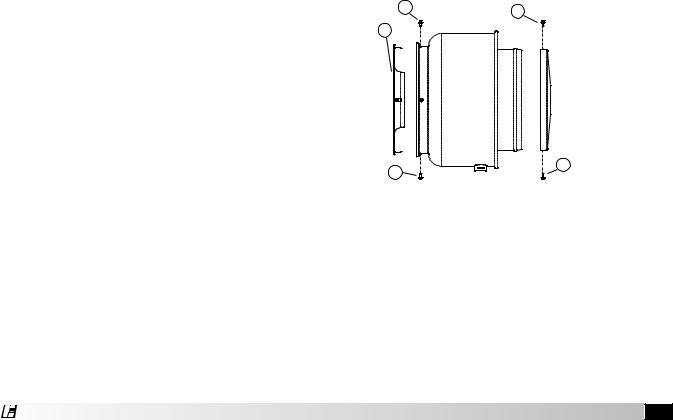
Typical Wall Mounting Installation
1.Remove mounting plate from unit by removing the fasteners shown above marked by (1). Remove motor compartment cover by removing fasteners marked by (2).
1 |
2 |
|
3
2
1
2.Locate the mounting plate (3) at the desired position and check to avoid unit clearance problems. Cut the wall opening (4) as shown based upon dimensions obtained from the Dimensional Data Section. Locate top of mounting plate (decal) and attach to the wall construction. The fasteners must pass through the holes provided in the mounting angle clips (5) on the mounting plate (3). For uneven surfaces, shims may be required. Sealant or caulking should be applied in the groove (6) formed by the mounting plate and the wall to prevent moisture leakage into the building.
Model CW/CWB • Centrifugal Sidewall Exhaust Fans 3
 Loading...