


Graham Field Mp701404, Mp7114, MM7074, MM7014, Mp7074 User Manual
...
service Manual for Basic American’s Matrix 709 series
InstructIons For use
etL/uL/csA Approved uL 60601-1 Iec 60601-2-38 csA 22.2 601.1
Basic American Medical products is a division of GF Health products, Inc. |
999-0807-190 • rev d • 2011 |
Basic American Medical Products
336 Trowbridge Drive Fond du Lac, WI 54937 www.basicamerican.com
For Matrix II Bed Service Parts please contact our Customer Service Department at 1-800-365-2338
GF Health Products, Inc.
2935A Northwest Parkway
Atlanta, GA 30360 www.grahamfield.com
To order a Matrix II Bed please contact a Graham Field Sales Representative at 1-800-554-9215
This service manual covers the following Matrix II Models:
Full-electric with standard caster carriage: 76” Grid = Mp7074; 80” Grid = Mp7174; 76” pan = Mp7014; 80” pan = Mp7114 Full-electric with M-Lok caster carriage: 76” Grid = MM7074; 80” Grid = MM7174; 76” pan = MM7014; 80” pan = MM7114 Full-electric with total Lock caster carriage: 76” Grid = Mp707404; 80” Grid = Mp717404; 76” pan = Mp701404; 80” pan = Mp711404
Important notIce
The information contained in this document is subject to change without notice.
Please check all parts for shipping damage and test before using.
In case of damage, DO NOT USE.
Copyright 2011 Basic American Medical Products

T ABLE OF CONTENTS
safety information and specifications
safety & warning information . . . . . . . . . . . . . . . . . . . . . . . 1 entrapment compliance information . . . . . . . . . . . . . . . . 2 bed features & specifications . . . . . . . . . . . . . . . . . . . . . . . . . 3
•Features & Mechanical Dimensions
•Electrical Specifications
•Available Options/Accessories
bed positioning specifications . . . . . . . . . . . . . . . . . . . . . . . . 4
•Maximum High and Low Bed Positions
•Maximum Head/Back Elevation/Angle
•Maximum Knee/Foot Elevation/Angle
operating your bed
operation - std. pendant/hand controller . . . . . . . . . . 5
• Pendant Diagram and Operational Instructions
operation - opt. staff/nurse control . . . . . . . . . . . . . . . . . 6
• Staff Diagram and Operational Instructions
board assembly & Misc. features
standard head- & footboards . . . . . . . . . . . . . . . . . . . . 7 - 10
•Std. Head- & Footboard Boring Patterns
•Assembly Instructions
•Head- & Footboard Assembly Parts
•Head- & Footboard Assembly Diagram
optional embedded staff control . . . . . . . . . . . . . . . . . . . . 11
•Assembly Instructions
•Footboard Embedded Control Parts & Diagram—single control box
standard & optional wallsavers . . . . . . . . . . . . . . . . . . . . . 13
•Assembly Instructions
•Standard Wallsaver & Side Wallsaver Assembly Parts
•Wallsaver Assembly Diagrams
standard mattress retainers . . . . . . . . . . . . . . . . . . . . . . . . 14
•Assembly Instructions
•Mattress Retainer Assembly Parts & Diagram
OPTIONAL edema foot ratchet . . . . . . . . . . . . . . . . . . . . . . . . 15
• Edema Diagram and Operational Instructions
accessories assembly
Head & foot half-rails . . . . . . . . . . . . . . . . . . . . . . . . . . . 17 & 18
• Diagram, Parts, and Assembly Instructions
Foot rail bracket assembly . . . . . . . . . . . . . . . . . . . . . . . . . . 19
• Diagram, Parts, and Assembly Instructions
Head & foot assist bars/rails . . . . . . . . . . . . . . . . . . . . 20 & 21
• Diagram, Parts, and Assembly Instructions
standard 4” extension pan . . . . . . . . . . . . . . . . . . |
. . . . . . . . 22 |
• Diagram, Parts, and Assembly Instructions |
|
optional 42” wide deck & Wide deck ext. pan |
. . . 23 & 24 |
• Diagram, Parts, and Assembly Instructions |
|
trapeze support . . . . . . . . . . . . . . . . . . . . . . . . . . . . . . |
. . . . . . . . 25 |
• Diagram, Parts, and Assembly Instructions |
|
bed parts and hardware |
|
Head, Knee & foot decks to main frame . . . . . . |
. . . . . . . 27 |
• Diagram, Parts, and Assembly Instructions |
|
main frame to u-levers AND DRAG LINK . . . . . . . . . . . . . . 28
• Diagram, Parts, and Assembly Instructions
LOWER u-levers to standard caster carriage . . . . . . . 29
• Diagram, Parts, and Assembly Instructions
LOWER u-levers to lock caster carriage w/m-lok . . . 30
• Diagram, Parts, and Assembly Instructions
electronics & cabling
head motor to head deck and main frame . . . . . . . . . 32
• Diagram, Parts, and Assembly Instructions
foot motor to knee deck and main frame . . . . . . . . . . 33
• Diagram, Parts, and Assembly Instructions
hi/lo motorS to drag linkS and u-leverS . . . . . . . . . . . . 34
• Diagram, Parts, and Assembly Instructions
control box connections & cabling . . . . . . . . . . . . . . . . 36
• Diagram, Parts, and Connection Instructions
Head, Foot, and Hi/Lo cable routing . . . . . . . . . . . . . 37 - 39
• Diagram and Routing Instructions
pendant cable & power cord routing . . . . . . . . . . 40 & 41
• Diagram and Routing Instructions
miscellaneous
electronic troubleshooting . . . . . . . . . . . . . . . . . . . . . . . . 42 recommended service and maintenance . . . . . . . . . . . . . 43 notes . . . . . . . . . . . . . . . . . . . . . . . . . . . . . . . . . . . . . . . . . . . . . . . . . 44
Basic American Medical products, a division of GF Health products, Inc.
S AFETY & WARNING INFORMATION - please read before operation
This product is a variable height, adjustable mattress platform, which will provide comfort and convenience for residents/patients and caregivers in long term care settings. All Warning/Caution labels attached to the bed apply to any hazards or unsafe practices that could result in personal injury and/or property damage. DO NOT remove any Warning/Caution labels attached to the bed. Whenever you see this symbol ! please pay special attention to the warning instructions and comments for your safety and the safety of the resident/patient.
IMPORTANT Safety Operating Information
!side rails, and accessories, taking into consideration proper positioning, patient size, realignment, transfer, and overall care, is 450 lbs.
MAKE SURE all electrical cords DO NOT get tangled around the bed, side rails, or legs during
!transport or normal operation of the bed. NEVER operate the bed if a Power Cord or Plug is damaged or not working properly. Contact qualified Service Personnel for examination and repair. ALWAYS unplug the Power Cord when performing any maintenance on the bed.
The bed’s Pendant Cord MUST BE ROUTED AND SECURED PROPERLY to ensure it does
!not become entangled and eventually severed during use.
MAKE SURE all locking casters and/or locking mechanisms are properly engaged when the
!bed is not in transport in order to avoid any rolling movement when the bed is at rest.
When operating the High/Low, Knee, or Back Functions of the bed, ALWAYS ensure that the
!confined individual is positioned properly within the confines of the bed. DO NOT let any extremities protrude over the side or between the bed rails when performing these functions.The MAXIMUM SAFE WORKING LOAD for the Matrix II Bed, including the mattress, panels,
!personnel perform work on these components, the manufacturer’s warranty becomes void.
DO NOT use unauthorized parts, accessories, or adapters other than those specified/authorized by Graham-Field Health Products.
!When using nasalor masked-type administering equipment, all oxygen or air tubing MUST
BE ROUTED AND SECURED PROPERLY to ensure that the tubing does not become entangled and eventually severed during the normal operation of the bed.
!Keep all moving parts free of obstructions (i.e. blankets/ sheets, heating blankets/pads, wiring, etc.)
!The bed is intended for use, storage, and transport within a temperature range of -40˚C to +60˚C. It has a water-resistance rating of IPX4 and IS NOT to be power-washed or submersed.DO NOT open assemblies such as the Actuators, Hand Control, or Control Box. If unauthorized
Operating Conditions
Operation of the bed is based on the following conditions:
Ambient Temperature of +10˚C to +40˚C; Relative Humidity of 30% to 75% (Non-condensing);
Atmospheric Pressure of 700hPa to 1060hPa; and a Splash Protection of IEC 60529.
!the frame for cleaning. This is also a safety feature for when the bed is powered down. ALWAYS make sure the deck is fully engaged in the upright position when lifting or lowering it manually.
Not doing so could result in damage to property or personal injury.
DO NOT lower the bed when objects are beneath it. Failure to inspect under the bed can result
!in damage to property or personal injury.
DO NOT use the side rails as push handles for moving the bed. Side rails can be deformed or
!broken if excessive side pressure is exerted. The purpose of the rails is to define the edge of the sleeping surface. They are not meant for patients considered as high risks for entrapment
(i.e. patients with pre-existing conditions such as confusion, restlessness, lack of muscle control, altered mental status, either organic or medicinal, or a combination thereof). Additional safety measures should be considered for such high-risk patients.
!NEVER permit more than one (1) person on/in the bed AT ANY TIME.
Body weight should be evenly distributed over the sleeping surface of the bed. DO NOT allow
!the patient to lay, sit, or lean in such a way that their entire body weight is placed only on the raised head or foot sections of the bed. This especially applies when repositioning or transferring
a patient in or out of the bed. Increased risk may occur when the patient’s size and/or weight are inappropriate for the bed’s dimensions or weight capacity.The head/back deck is designed to remain in its full upright angled position when accessing
Storage
Storage of the bed is based on the following conditions:
Ambient Temperature of -10˚C to 70˚C; Relative Humidity of 10% to 100%; and an Atmospheric
Pressure of 500hPa to 1060hPa.
Radio Frequency Interference (RFI)
RFI influences most electronic equipment. Caution should be exercised with regard to the use of portable communications equipment in the area around such equipment. If RFI causes erratic behavior, shut the bed off immediately. Leave it off while the transmission is in progress.
label symbol definitions
! !
consult |
safe |
protected |
type B |
Accompanying |
Working |
Grounded |
equipment & |
documents |
Load |
device |
Applied parts |
Basic American Medical products, a division of GF Health products, Inc. • Matrix II • rev d Manual |
p1 |

E ntrapment compliance information
On March 10, 2006, the FDA (U.S. Food and Drug Administration) released long-awaited guidelines for reducing the risk of bed entrapment: “Hospital Bed System Dimensional and Assessment Guidance to Reduce Entrapment”. The new Guidance identifies potential entrapment areas and those body parts most at risk for entrapment; provides design criteria for manufacturers of new hospital/convalescent beds; recommends particular test methods to assess the conformance of existing hospital/convalescent bed systems; and answers frequently-asked questions about entrapment issues.
The new Guidance was a result of a long-standing collaboration between the FDA and the Hospital Bed Safety Workgroup (HBSW), formed in 1999. Graham-Field’s Long-Term Care Bed division: Basic American Medical Products, is an HBSW charter member. As a result of Graham-Field’s commitment to product safety, all of Graham-Field current long-term care beds have been strictly tested and conform to the new FDA Guidance.
The guidelines set forth by the FDA Guidance layout specific dimensional limitations on potentially injury-threatening gaps and spaces that can occur between bed system components, such as rails, when not properly installed. Graham-Field and Basic American Medical Products have conformed to these guidelines from a manufacturing aspect. However, entrapment issues can often arise when a healthcare provider/facility has not correctly assembled the components on a bed. It is essential that the provider/ facility fully understand their responsibility in complying to the guidelines set forth by the FDA in order to avoid injury. To that end, we have provided the links below as a resource for understanding and following these guidelines for the safety of the patient/resident.
Graham-Field encourages all hospital bed owners to read the FDA guidance.
Please visit the FDA’s Hospital Bed Safety page at "http://www.fda.gov/cdrh/beds/"
To find many resources, including a link to the new Guidance page go to "http://www.fda.gov/cdrh/beds/guidance/1537.pdf"
Ordering instructions for a Testing Kit which you can use to determine whether your beds are in conformance with the guidance can be found at "http://www.fda.gov/cdrh/beds/entrapmentkit.html"("http://www.fda.gov/cdrh/beds/entrapmentkit.html" http://www.fda.gov/cdrh/beds/entrapmentkit.html) ;
A discussion of Clinical Guidance protocol which you can use to assess an individual patient’s needs when using a side rail can be found at "http://www.ute.kendal.org/learning/documents/clinicalguidance_SideRails.pdf"
These resources will supply you with the knowledge to evaluate the safety of the hospital beds you currently own.
It is also essential to have the correct bed components/accessories that correspond with the needs of your patient/resident and the particular bed you have purchased. Matching the correct bed component that correlates with the regulatory guidelines can be a daunting task. Our Graham-Field Sales team and the friendly Customer Service Representatives at Basic American Medical Products can help you sift through the wide array of compliance and bed options. We will help you determine which bed/bed part is best for your patient’s/resident’s particular needs and help you with your compliance issues.
Basic American Medical products, a division of GF Health products, Inc. • Matrix II • rev d Manual |
p2 |

B ED features & SPECIFICATIONS
The Matrix II Full-Electric Bed Series offers some outstanding standard and optional features all geared for safety and comfort. We have included both mechanical and electrical specifications below for your records. *We are excited to introduce a new Anti-Microbial Powder Coat Painting process which has been proven to inhibit the growth of damaging and disease causing microbes (bacteria, mold, fungus, algae, etc.) on the surface of coated items. Recorded result-reduction of bacteria has been 99.9%.
Features
Sleep Surface Availability |
76” & 80” |
|
|
|
|
Sleep Surface Options |
Steel Welded Wire Grid (std) |
|
or Pan |
||
|
||
|
|
|
Sleep Surface Material |
11 GA. Hot Rolled Steel |
|
|
|
|
Base Frame Material |
Welded Tubular |
|
|
|
|
Main Frame Material |
Steel (Rectangular |
|
& Square Tubing) |
||
|
||
|
|
|
Travel Range |
8.90” to 25.00” |
|
|
|
|
Standard Locking System |
Lock and/or Roll |
|
at any height |
||
|
||
|
|
|
Baseboard Wallsaver |
Wire - Standard |
|
|
|
|
Mattress Retainers |
Two std. on foot deck |
|
|
|
|
Hand Pendant |
6-function with long |
|
coil cord |
||
|
||
|
|
|
Pendant Holster |
Standard |
|
|
|
|
Motors & Control Box |
Quiet DC Electronics |
|
|
|
|
Heavy Duty Casters |
Four Standard |
|
|
|
|
*Anti-Microbial Powder Coat |
Soft Pantone Grey |
|
Paint Finish |
||
|
||
|
|
|
Entrapment |
FDA Compliant |
|
|
|
Mechanical Dimensions
|
76” |
80” |
|
|
|
|
|
Overall Bed Length |
82.00” |
86.00” |
|
(with standard wallsaver) |
|||
|
|
||
|
|
|
|
Overall Bed Width |
39.75” |
39.75” |
|
(with standard rails) |
|||
|
|
||
|
|
|
|
Overall Bed Width |
36.00” |
36.00” |
|
(with standard boards-no rails) |
|||
|
|
||
|
|
|
|
Sleep Deck Surface Length |
75.00” |
79.00” |
|
|
|
|
|
Sleep Deck Surface Width |
35.00” |
35.00” |
|
|
|
|
|
Sleep Deck Surface Height |
25.00” |
25.00” |
|
(high position) |
|||
|
|
||
|
|
|
|
Sleep Deck Surface Height |
8.90” |
8.90” |
|
(low position) |
|||
|
|
||
|
|
|
|
Under Bed Minimum Clearance |
5.25” |
5.25” |
|
(high position) |
|||
|
|
||
|
|
|
|
Maximum Head Deck Angle |
70º |
70º |
|
|
|
|
|
Maximum Knee Deck Angle |
30º |
30º |
|
|
|
|
|
Maximum Knee to Leg Angle |
45º |
45º |
|
|
|
|
|
Maximum Safe Working Load |
450 lbs. |
450 lbs. |
|
|
|
||
(including mattress, panels, side |
|
|
|
rails and accessories, and taking |
|
|
|
into consideration patient size, |
|
|
|
proper positioning, realignment, |
|
|
|
transfer, and overall care. |
|
|
|
|
|
|
electrical specifications
Power/Frequency |
120 Volt/60 Hz |
|
|
|
|
Current Actuator Rating |
LA27 |
|
|
|
|
Overall Movement Draw |
4 Amps |
|
|
|
|
Classification |
Class I, Type B |
|
|
|
|
Mode of Operations |
10% Max. Duty Cycle |
|
2 minutes on/18 minutes off |
||
|
||
|
|
|
Electrical Cord |
Type SJT 3/18AWG |
|
Grounded w Hospital Plug |
||
|
||
|
|
options/accessories
One Step Locking |
Foot end/360º roll |
|
Mechanism |
||
|
||
Std. 4” Pan Extension Kit |
Foot end - adds 4” to length |
|
|
|
|
Staff/Nurse Control |
Embedded in Footboard |
|
|
|
|
Lockout |
Economy or Single |
|
|
|
|
Tubular Wallsaver |
Steel |
|
|
|
|
Side Rails |
LH and RH/Head or Foot |
|
|
|
|
Assist Bar |
LH or RH/Head or Foot |
|
|
|
|
Edema Foot Ratchet |
Foot end |
|
|
|
|
Trapeze |
Support & Bar |
|
|
|
|
Traction |
Adapter & IV Socket |
|
|
|
|
Battery Backup |
Charger, Cable & Battery |
|
|
|
|
Standard Pan Deck |
Pan Head, Knee & Foot |
|
|
|
|
42” Wide Deck Kit |
Two RH & two LH Sections |
|
|
|
|
Wide 4” Pan Extension Kit |
Foot end - adds 4” to length |
|
|
|
NOTE: When ordering parts or contacting our customer service department, please have the bed’s model and serial number available. These can be found on the identification labels which are usually located on the bed frame under the sleep deck.
Basic American Medical products, a division of GF Health products, Inc. • Matrix II • rev d Manual |
p3 |
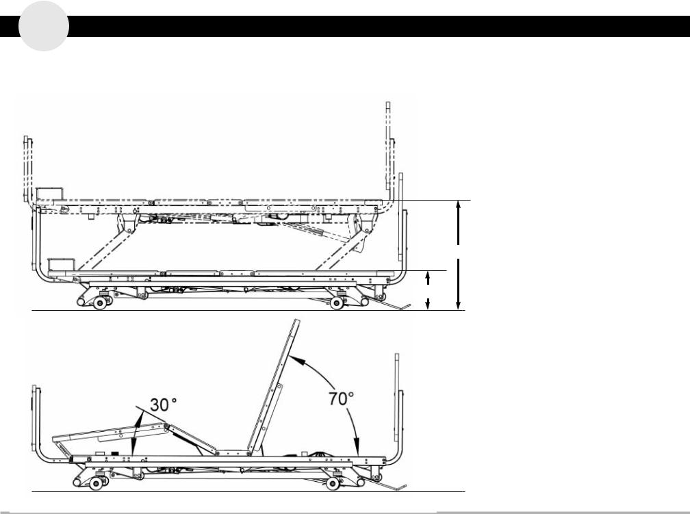
P ositioning Specifications
The Matrix II Bed Series has infinite positions that serve to help the patient be more comfortable and gives the practitioner easy access during procedures, transfers, etc. The correct placement of the bed is essential for the patient’s safety.
The bed should always be set to its lowest position when the patient is left unattended. The head and knee functions allow the resident/patient to raise their head or legs.
Floor
The recommended maximum distance for the head function is 70˚. In the event of a power outage, it is preferred that the knee and back sections be lowered using an emergency battery pack. If unavailable, the sections can be set into the flat position by easily removing the actuator mounting pins.
25.00”
8.90”
QUICK REFERENCE:
MAXIMUM (High Position)
Bed height from floor to sleep deck top = 25.00”
MINIMUM (Low Position) Bed height from floor to sleep deck top = 8.90”
DISTANCE TO WALL (High)
Headboard mounting tube to end of std. wallsaver = 1.75”
DISTANCE TO WALL (Low) Headboard mounting tube to end of std. wallsaver = 1.50”
MAXIMUM (Head Angle) Head deck to sleep surface = 70º
MINIMUM (Knee Angle)
Knee deck to sleep surface = 30º
MAXIMUM (Knee/Foot Angle)
Knee deck to foot deck = 45º
Basic American Medical products, a division of GF Health products, Inc. • Matrix II • rev d Manual |
p4 |
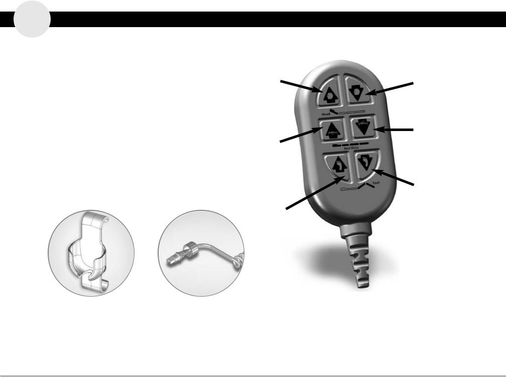
O PERATION OF STANDARD PENDANT/HAND CONTROLLER
Easy Patient Controls
Each Matrix II Bed is equipped with a pendant-type hand control— standard. Each control function (head, bed, and knee) has two easily recognizable switches for up and down movement. The pendant can be easily disconnected to deactivate the patient control functions.
The controls are designed so that more than one function can be activated simultaneously. To operate, push the appropriate buttons to activate the desired function.
Pendant Holster |
Male End Connector |
999-0791-000 |
of Pendant Cable |
Raise =
Head Up
Raise =
Bed Up
Raise =
Knees Up
Lower =
Head Down
Lower =
Bed Down
Lower =
Knees Down
Model # HB00 part # 999-0775-305
(Also includes alligator clip 100-0510-001)
Basic American Medical products, a division of GF Health products, Inc. • Matrix II • rev d Manual |
p5 |

O PERATION OF OPTIONAL STAFF/NURSE CONTROL
part # 999-0775-901
Staff/nurse Controller
The staff/nurse control allows the caregiver to individually lock out all functions of only the pendant control. The caregiver can also operate the bed from this panel without walking to the side of the bed.
To Operate the Travel Controls
Press the “HOLD SELECT” (#13) first, then the appropriate “UP” (#4, 6, or 8) OR “DOWN” (#5, 7, or 9) on the panel.
To Lock Out a Pendant Function
Press the “HOLD SELECT” (#13) first, then the appropriate “NO PENDANT” (#1, 2, or 3) on the panel. The corresponding illuminated LED light (#10, 11 &12) indicates that the function is now locked out on the pendant.
To Unlock a Pendant Function
Press the “HOLD SELECT” (#13) first, then the appropriate "NO PENDANT" (#1, 2, or 3) on the panel. The corresponding LED light (#10, 11 & 12) is no longer illuminated, indicating that the pendant can now operate that function.
Lockout Led LIGHt |
Lockout Led LIGHt |
Lockout Led LIGHt |
STAFF CONTROL REFERENCE
Head LED Light |
Item 10 |
|
|
Foot LED Light |
Item 11 |
|
|
Hi/Lo LED Light |
Item 12 |
|
|
Hold & Select Button |
Item 13 |
|
|
TO OPERATE BED FROM STAFF CONTROL |
|
|
|
Raise Head/Back Deck |
Push 13 then 4 |
|
|
Lower Head/Back Deck |
Push 13 then 5 |
|
|
Raise Knee/Foot Decks |
Push 13 then 6 |
|
|
Lower Knee/Foot Decks |
Push 13 then 7 |
|
|
Raise Entire Bed (Hi/Lo) |
Push 13 then 8 |
|
|
Lower Entire Bed (Hi/Lo) |
Push 13 then 9 |
|
|
TO LOCK OUT HAND CONTROL FUNCTION |
|
|
|
Lock Out Head Function |
Push 13 then 1 |
|
|
Lock Out Foot Function |
Push 13 then 2 |
|
|
Lock Out Hi/Lo Function |
Push 13 then 3 |
|
|
PLEASE NOTE:
When the Pendant Hand Controller is locked out, you can still operate the bed from the Staff/Nurse Control without unlocking the pendant hand controller.
Head deck |
|
HI/LO (raise bed) |
foot deck |
functions & |
hold |
functions & |
functions & |
lockout |
|
lockout |
lockout |
|
|
|
|
Basic American Medical products, a division of GF Health products, Inc. • Matrix II • rev d Manual |
p6 |

HEAD- & FOOTBOARDS
Basic American Medical products, a division of GF Health products, Inc. • Matrix II • rev d Manual |
p7 |
Standard Headboard and Footboard BORING DIAGRAM
The diagrams below outline the manufacturer’s standardized headboard and footboard boring specifications. All of the dimensions are referenced from the center and bottom. Before making any significant variations to these dimensions, please contact the manufacturer.
HeAdBoArd
FootBoArd
Basic American Medical products, a division of GF Health products, Inc. • Matrix II • rev d Manual |
p8 |

A ssembly - standard head and foot boards
1.Assemble two Mounting Tubes (#4) to the Headboard (#1) and two to the Footboard (#2) using eight 1/4-20 x 4mm JCB-B Hex Drive Bolts (#6), going through the pre-drilled holes on the boards and into the eight 1/4-20 x .60” Long Threaded Inserts (#3) (already attached to the boards) as shown. Hand tighten only at this time.
2.Insert the Mounting Tubes into the Main Bed Frame Tubes so that the holes match up as shown. Secure with four 5/16 x 1-1/2” Clevis Pins (#7) and 1-9/16 Hair Pin Clips (#8) (1 each per bed frame tube). The mounting tubes will slide underneath the two 5/16-18 x 1.50” Carriage bolts that were pre-inserted into the Main Frame Rails at the head-end of the bed by the manufacturer.
3.Now tighten all screws with a phillips screwdriver. Be careful not to overtighten.
Item # |
Quantity |
Part # |
Description |
|
|
|
|
|
|
1 |
1 |
- |
Headboard* |
|
|
|
|
|
|
2 |
1 |
- |
Footboard* |
|
|
|
|
|
|
3 |
8 |
100-7025-004 |
1/4-20 UNC x .60” Long Threaded Insert |
|
(pre-inserted into footboard and headboard) |
||||
|
|
|
||
|
|
|
|
|
|
Headboard & Footboard Mounting Kit (999-0775-000) includes the following parts: |
|||
|
|
|
|
|
4 |
4 |
999-0746-035G |
Mounting Tubes |
|
|
|
|
|
|
5 |
4 |
100-4700-015 |
1” x 1” Square Tube End Cap (pre-inserted in tubes) |
|
|
|
|
|
|
6 |
8 |
100-5425-094 |
1/4-20 x 4mm JCB-B Hex Drive Bolt |
|
|
|
|
|
|
7 |
4 |
100-7931-007 |
Clevis Pin - 5/16 x 1-1/2” w/cross hole |
|
|
|
|
|
|
8 |
4 |
100-2001-006 |
1-9/16 Hair Pin Clip |
|
|
|
|
|
|
not shown |
1 |
100-9900-060 |
M4 4mm Hex Allen Wrench |
|
|
|
|
|
|
|
Hardware Pre-inserted into Main Frame Rails to Hold Mounting Tubes |
|||
|
|
|
|
|
9 |
2 |
100-5231-003 |
5/16-18 x 1.50” Carriage Bolt |
|
|
|
|
|
|
10 |
2 |
100-6731-006 |
5/16-18 Thin Nylon Lock Nut |
|
|
|
|
|
|
*There are a number of stylish options for Matrix II Headboards and Footboards including Oak, Walnut, and Mahogany finishes. Please consult your catalog, our website (www.graham-field.com), or contact one of our Sales Representatives for options. Please note that headboards and footboards come as a kit and are not interchangeable.
Basic American Medical products, a division of GF Health products, Inc. • Matrix II • rev d Manual |
p9 |
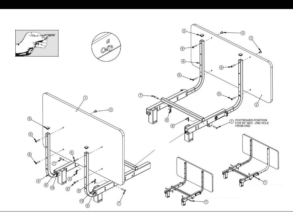
Standard Headboard and Footboard Assembly
Standard beds do NOT include Staff Control. (Complete footboard assembly with staff control shown on page 11)
close-up of Hair pin clip (#8) inserted into hole in clevis pin (#7)
to safely remove Hair pin clip
grasp on circular end and pull.
Tools Needed:
(1) Phillips Screwdriver
tube end caps are pre-assembled on Mounting tubes
HEADBOARD
threaded Inserts are pre-assembled
on Headboard
tube end caps are pre-assembled on Mounting tubes
Main Frame
Weldment
threaded Inserts are pre-assembled
on Footboard
FOOTBOARD
Staff control not shown.
FootBoArd posItIon For 76” Bed - 3rd HoLe FroM end
FootBoArd posItIon For 84” Bed - 1st HoLe FroM end
Basic American Medical products, a division of GF Health products, Inc. • Matrix II • rev d Manual |
p10 |
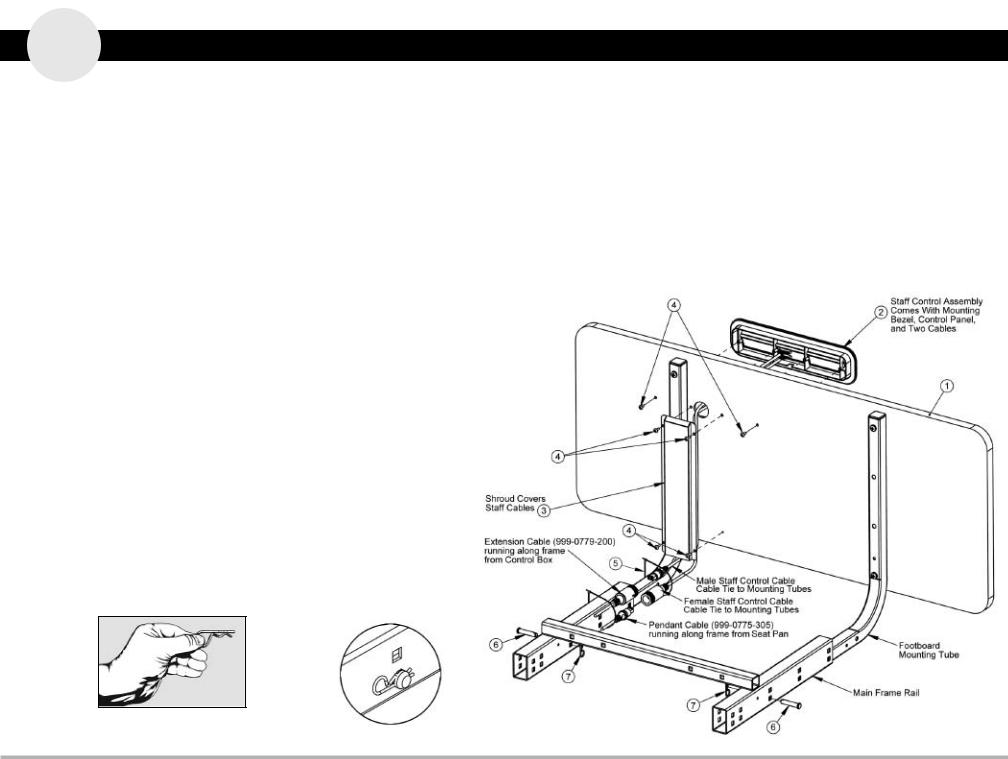
A ssembly - OPTIONAL foot board EMBEDDED STAFF CONTROL
Item # |
Qty |
Part # |
Description |
|
|
|
|
|
STAFF CONTrOL ASSEMBLy KIT (ZL788053) INCLuDES: |
||
|
|
|
|
1 |
1 |
Z53650 |
Std. Oak Head- & Footboard (with cut out) |
|
|
|
|
2 |
1 |
999-0775-901 |
Staff Control Assembly with Cables |
|
|
|
|
3 |
1 |
999-0775-006G |
Wide Staff Control Shroud |
|
|
|
|
4 |
6 |
100-5506-002 |
#6 x .50” Phillips Truss Head Screws (Blk) |
|
|
|
|
5 |
3 |
100-1100-024 |
4” Nylon Cable Tie |
|
|
|
|
|
|
Mounting Tube to Main Frame Hardware |
|
|
|
|
|
6 |
2 |
100-7931-007 |
5/16 x 1.50” Clevis Pin w/hole (existing) |
|
|
|
|
7 |
2 |
100-2001-006 |
1-9/16 x .072 Hair Pin Clip (existing) |
|
|
|
|
1.Assemble the footboard mounting tubes to the “staff control footboard” as shown on the previous pages if not already assembled. Note that the standard footboard does not have the cut outs for the staff control assembly. A separate footboard with cut outs must be ordered for the staff controller option.
2.Facing the footboard from the foot-end of the bed, carefully thread the male and female staff control cables through the hole in the footboard and position
the staff control assembly (#2) into the pre-formed slot on the footboard, making sure all screw holes line up correctly. Using two black
#6 X .50” Phillips Truss Head Screws (#4), from the back of the footboard secure the Staff Control via the outermost holes.
3.Place the Staff Control Shroud (#3) over the cables on the back of the footboard and attach with four black #6 X .50” Phillips
Truss Head Screws (#4). Lightly tighten all screws with a phillips screwdriver. Tie the cables to the mounting tubes with ties (#5).
4.Insert the Footboard Mounting Tubes into the Main Bed Frame Tubes so that the holes match up as shown. Secure with two 5/16 x 1-1/2” Clevis Pins (#6) and Hair Pin Clips (#7) (1 each per bed frame tube).
5.Unplug the Pendant cable from the Extension Cable that’s already attached to the left side frame rail at the foot end of the bed.
6.Plug the male staff control cable into the cable extension that has been plugged into the control box in the HB Port. Plug the Pendant cable into the female staff control cable.
7.Tighten all screws on the Footboard with a phillips screwdriver. Be careful not to overtighten.
close-up of Hair pin clip (#6) inserted into hole in clevis pin (#7)
to safely remove Hair pin clip grasp on circular end and pull.
Tools Needed:
(1) Phillips Screwdriver
Basic American Medical products, a division of GF Health products, Inc. • Matrix II • rev d Manual |
p11 |

WALLSAVERS, MATTRESS RETAINERS
& EDEMA RATCHETS
Basic American Medical products, a division of GF Health products, Inc. • Matrix II • rev d Manual |
p12 |
 Loading...