


9000APS

INSTRUCTIONS FOR USE
SERVICE MANUAL
To avoid personal injury or damage to bed,
please read all sections pertaining to
your bed model before use.
Basic American Medical Products, a division of GF Health Products, Inc. www.grahamfield.com Zenith APS Service Manual 999-0831-190A
ETL/UL/CSA APPROVED
UL 60601-1
IEC 60601-2-38
CSA 22.2 601.1

This service manual covers the following APS Models:
76” & 80” Full Electric with Pedal Lock Caster System & Grid Decks = APS98174;
76” & 80” Full Electric with Pedal Lock Caster System, Grid Decks, and Underbed Light = APS981741;
76” & 80” Full Electric with Pedal Lock Caster System, Grid Decks, Underbed Light, and
Onboard Battery Backup System = APS981742.
IMPORTANT NOTICE
GF Health Products, Inc. is not responsible for typographical errors.
All illustrations, specifications, packaging, and warranties contained in this Service Manual
are based on the latest product information available at the time of printing.
The most current product information can be found online at www.grahamfield.com.
Please check all parts for shipping damage and test before using.
In case of damage, DO NOT USE.
,#&+#'#%+(.-,
336 Trowbridge Drive
Fond du Lac, WI 54937
For APS 9000 Bed Service Parts please contact
our Customer Service Department at
1-800-365-2338
%-"+(.-,'
2935A Northwest Parkway
Atlanta, GA 30360
www.grahamfield.com
To order an APS 9000 Bed please contact a
Graham Field Sales Representative at
1-800-554-9215

Basic American Medical Products, a division of GF Health Products, Inc. www.grahamfield.com 999-0831-190A Service Manual
Zenith aps seRies
3
TABLE OF CONTENTS
Safety & Warnings . . . . . . . . . . . . . . . . . . . . . . . . . . . . . 4
ID/Warning Labels . . . . . . . . . . . . . . . . . . . . . . . . . . . 5 - 6
Entrapment/Compliance . . . . . . . . . . . . . . . . . . . . . . . . . 7
Features & Specifications . . . . . . . . . . . . . . . . . . . . . . . . 8
Unpacking Your New Bed . . . . . . . . . . . . . . . . . . . . . . . . 9
Assembly - Boards . . . . . . . . . . . . . . . . . . . . . . . . . . . . . 10
Plugging in Your Staff Control . . . . . . . . . . . . . . . . . . . . 11
Standard Mattress Retainers . . . . . . . . . . . . . . . . . . . . . 12
Standard Wireform Wallsaver . . . . . . . . . . . . . . . . . . . . 13
Wallsaver Adapter for Trendelenberg Positions . . . . . . .14
Operations/Controllers & Staff Control . . . . . . . . . .15 - 16
Placing the Bed into the Chair Position . . . . . . . . . . . . .17
Using Trendelenberg/Reverse Trendelenberg . . . . . . . .18
Electronic Components . . . . . . . . . . . . . . . . . . . . . . . . . 19
Electrical Cabling . . . . . . . . . . . . . . . . . . . . . . . . . . 20 - 22
Optional Pivot Assist Bar . . . . . . . . . . . . . . . . . . . . . . . .23
Optional Trapeze Support Adaptor . . . . . . . . . . . . . . . . .24
Optional Battery Backup Configurations . . . . . . . . . . . . .25
Troubleshooting - No Power . . . . . . . . . . . . . . . . . . . . . 26
Troubleshooting - Staff Control & Pendant . . . . . . . 26 -27
Troubleshooting Motors/Control Box . . . . . . . . . . . . . . . 28
Replacing the Staff Control Assembly . . . . . . . . . . . . . . 29
Maintenance & Inspection . . . . . . . . . . . . . . . . . . . . . . .30
Replacement/Service Part List . . . . . . . . . . . . . . . . 31-32
Service Part Diagrams . . . . . . . . . . . . . . . . . . . . . . . 33-36
Protected
Grounded
Device
Safe
Working
Load
Consult
Accompanying
Documents
Type B
Equipment &
Applied Parts
!
!
Double
Insulated
Basic American Medical Products, a division of GF Health Products, Inc. www.grahamfield.com 999-0831-190A Service Manual
4
This product is a variable height, adjustable mattress
platform, which will provide comfort and convenience
for residents/patients and caregivers in long term
care settings.
The MAXIMUM SAFE WORKING LOAD for the
APS 9000 Bed with weight evenly distributed
, including
bedding, resident/patient, support surface, and all
accessories, is 600 lbs.
NEVER operate the bed if a Power Cord or Plug is
damaged or not working properly. Contact qualified
Service Personnel for examination and repair. Always
unplug the Power Cord when performing any mainte-
nance on the bed.
DO NOT open assemblies such as the Actuators, Hand
Control, or Control Box. If unauthorized personnel
perform work on these components, the manufacturer’s
warranty becomes void.
DO NOT use unauthorized parts, accessories, or
adaptors other than those specified/authorized by
GF Health Products, Inc.
When operating the High/Low, Knee, or Back Functions
of the bed, ALWAYS ensure that the confined individual
is positioned properly within the confines of the bed.
DO NOT let any extremities protrude over the side or
between the bed rails when performing these functions.
DO NOT lower the bed when objects are beneath it.
Failure to inspect under the bed can result in damage
to property or personal injury.
The bed’s Pendant Cord MUST BE ROUTED AND
SECURED PROPERLY to ensure it does not become
entangled and eventually severed during use. Also
make sure all electrical cords DO NOT get tangled
around the bed, side rails, or legs during transport or
normal operation of the bed.
When using nasal- or masked-type administering
equipment, all oxygen or air tubing MUST BE ROUTED
AND SECURED PROPERLY to ensure that the tubing
does not become entangled and eventually severed
during the normal operation of the bed.
The bed should ALWAYS be left in its lowest position
when unattended to reduce the risk of injury while getting
in or out of the bed.
Keep all moving parts free of obstructions (i.e. blankets/
sheets, heating blankets/pads, wiring, etc.)
DO NOT use the assist devices as push handles for moving
the bed. Assist devices can be deformed or broken if
excessive side pressure is exerted. Assist devices are not
meant for patients considered as high risks for entrapment
(i.e. patients with pre-existing conditions such as
confusion, restlessness, lack of muscle control, altered
mental status, either organic or medicinal, or a combi-
nation thereof). Additional safety measures should be
considered for such high-risk patients.
NEVER permit more than one (1) person on/in the bed
at any time.
Body weight should be evenly distributed over the
sleeping surface of the bed. DO NOT allow the patient
to lay, sit, or lean in such a way that their entire body
weight is placed only on the raised head or foot sections
of the bed. This especially applies when repositioning
or transferring a patient in or out of the bed. Increased
risk may occur when the patient’s size and/or weight are
inappropriate for the bed’s dimensions or weight capacity.
The bed is intended for use, storage, and transport within
a temperature range of -40˚C to +60˚C. It has a water-
resistance rating of IPX4 and IS NOT
to be power-
washed or submersed.
!
!
!
!
!
!
!
!
!
!
!
!
!
!
!
)+-#'!('#-#(',
Operation of the bed is based on the following conditions:
Ambient Temperature of +10˚C to +40˚C; Relative Humidity
of 30% to 75% (Non-condensing); Atmospheric Pressure of
700hPa to 1060hPa; and a Splash Protection of IEC 60529.
-(+!
Storage of the bed is based on the following conditions:
Ambient Temperature of -10˚C to 70˚C; Relative Humidity
of 10% to 100%; and an Atmospheric Pressure of 500hPa
to 1060hPa.
#(+*.'1'-+ +'
RFI influences most electronic equipment. Caution should be
exercised with regard to the use of portable communications
equipment in the area around such equipment. If RFI causes
erratic behavior, shut the bed off immediately. Leave it off
while the transmission is in progress.
Zenith aps seRies
IMPORTANT SAFETY AND WARNING INFORMATION
Basic American Medical Products, a division of GF Health Products, Inc. www.grahamfield.com 999-0831-190A Service Manual
5
GF HEALTH
PRODUCTS, INC.
DUTY CYCLE - 2 min Continuous/18 min
MODE OF OPERATION - Intermittent
600 lbs
SAFE WORKING LOAD
=
IPX4
MODEL NO
806-0000-000000
SERIAL NO
000000000000
MFG. DATE
12/23/11
VOLT HZ AMP TYPE
110-120 50/60 4.5 AC
!
ETL
Logo
APS98174
MODEL NO. 806-0000-000000 MFG DATE 12/23/11
SERIAL APS 9
SERIAL APS98174
SERIAL APS 9
ZENITH 806 SERIES
PATENT PENDING
APS9000
000000000000
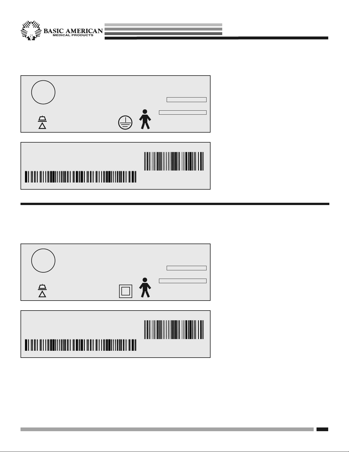
Bed labels are an important part of
identifying your bed’s make and model
when ordering replacement parts. The
Serial Number is essential if you are
claiming parts or service under warranty.
These helpful labels can be located on
the main frame rails, immediately below
the sleep decks on either side of the bed.
Please have this IMPORTANT infor-
mation ready when calling our customer
service or technical support staff at
800-365-2338; it will allow us to better
assist you and quickly answer your
questions and concerns.
Zenith aps seRies
TYPICAL APS 9000 BED IDENTIFICATION LABELS
with Grounded Electrical Cable
TYPICAL APS 9000 BED IDENTIFICATION LABELS
for Class II Models
If you opted for an electrical system without
grounding on your electrical cord, your bed
is designated as a Class II.
The Identification bed labels to the left
represent the labels for Class II beds.
They can be located on the main frame
rails, immediately below the sleep decks
on either side of the bed.
Please have this IMPORTANT information
ready when calling our customer service
or technical support staff at 800-365-2338.
The labels at left will allow us to better
assist you in answering your questions
and concerns.
GF HEALTH
PRODUCTS, INC.
DUTY CYCLE - 2 min Continuous/18 min
MODE OF OPERATION - Intermittent
600 lbs
SAFE WORKING LOAD
=
IPX4
MODEL NO
806-0000-000000
SERIAL NO
000000000000
MFG. DATE
12/23/11
VOLT HZ AMP TYPE
110-120 50/60 4.5 AC
!
ETL
Logo
APS98174
MODEL NO. 806-0000-000000 MFG DATE 12/23/11
SERIAL APS 9
SERIAL APS98174
SERIAL APS 9
ZENITH 806 SERIES
PATENT PENDING
APS9000
000000000000
Basic American Medical Products, a division of GF Health Products, Inc. www.grahamfield.com 999-0831-190A Service Manual
6
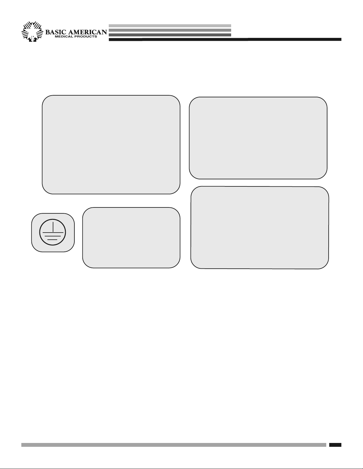
WARNING!
DO NOT LOWER BED WHEN OBJECTS ARE
BENEATH BED. FAILURE TO INSPECT UNDER
BED CAN RESULT IN DAMAGE TO PROPERTY
OR PERSONAL INJURY.
ATTENTION:
S’assurer de ne pas faire descendre le lit
lorsque des objets se trouvent sous le lit. Ne
pas inspecter le dessous du lit pourrait entrainer
des dommages materiels et des risques de
blessures.
WARNING!
DO NOT LOWER BED WHEN
OBJECTS ARE BENEATH BED.
FAILURE TO INSPECT UNDER
BED CAN RESULT IN DAMAGE
TO PROPERTY OR PERSONAL
INJURY.
CAUTION
THIS BED IS SUITABLE FOR USE ONLY WITH
OXYGEN ADMINISTERING EQUIPMENT OF
THE NASAL OR MASK TYPE OR A TENT
COVERING ONLY THE UPPER HALF (HEAD
END) OF THE BED. OXYGEN TENT CANOPIES
SHOULD NOT EXTEND BELOW BED SPRING
LEVEL. LOCK HAND CONTROL AT FOOT OF
BED WHEN USING OXYGEN ADMINISTERING
EQUIPMENT.
ATTENTION:
CE LIT PEUT ETRE UTILISE UNIQUEMENT
AVEC UN EQUIPMENT DESTINE A
L’ADMINISTRATION D’OXYGENE DE TYPE
NASAL OU MASQUE OU AVEC UNE TENTE
RECOUVRANT SEULEMENT LA MOTTIE
AVENT (TETE) DU LIT. LES COTES DE LAS
TENTE OXYGENE NE DOIVENT PAS SE
PROLONGER PLUS DAS QUE LA SOMMIER
DU LIT.
The following warning labels have been placed on your bed to help protect you and your bed from
damage. Please do not remove any labels from your bed.
Zenith aps seRies
TYPICAL SAFETY/WARNING BED LABELS

Basic American Medical Products, a division of GF Health Products, Inc. www.grahamfield.com 999-0831-190A Service Manual
7
On March 10, 2006, the FDA (U.S. Food and Drug Adminis-
tration) released long-awaited guidelines for reducing the risk
of bed entrapment: “Hospital Bed System Dimensional and
Assessment Guidance to Reduce Entrapment”. The new Guidance
identifies potential entrapment areas and those body parts most
at risk for entrapment; provides design criteria for manufacturers
of new hospital/convalescent beds; recommends particular test
methods to assess the conformance of existing hospital/conva-
lescent bed systems; and answers frequently-asked questions
about entrapment issues.
The new Guidance was a result of a long-standing collaboration
between the FDA and the Hospital Bed Safety Workgroup
(HBSW), formed in 1999. GF Health Products, Inc’s Long-
Term Care Bed division: Basic American Medical Products, is
an HBSW charter member. As a result of our commitment to
product safety, %%(.+.++'-%('!-+&+,"/'
,-+#-%1-,-'(' (+&-(-"'0.#'.
The guidelines set forth by the FDA Guidance layout specific
dimensional limitations on potentially injury-threatening gaps
and spaces that can occur between bed system components,
such as rails, when not properly installed. GF Health Products,
Inc. and Basic American Medical Products have conformed
to these guidelines from a manufacturing aspect. However,
entrapment issues can often arise when a healthcare provider/
facility has not correctly assembled the components on a bed.
It is essential that the provider/facility fully understand their
responsibility in complying to the guidelines set forth by the
FDA in order to avoid injury. To that end, we have provided
the FDA’s web address at right as a resource for understanding
and following these guidelines for the safety of patients/residents.
It is also essential to have the correct bed components/acces-
sories that correspond with the needs of your patient/resident
and the particular bed you have purchased. Matching the correct
bed component that correlates with the regulatory guidelines can
be a daunting task. Our sales team at GF Health Products, Inc.
and our friendly Customer Service Representatives at Basic
American Medical Products can help you sift through the wide
array of compliance and bed options. We will help you determine
which bed/bed part is best for your patient’s/resident’s particular
needs and help you with your compliance issues.
"',,(+#,%#,-#'-"#,
&'.%+#' .%%(&)%#'0#-"!.#%#',
(++.#'!-"+#,$( '-+)&'-2Hospital
Bed System Dimensional and Assessment Guidance
to Reduce Entrapment3
-#%,' (.'-000 !(/
Zenith aps seRies
ENTRAPMENT & COMPLIANCE INFORMATION

Basic American Medical Products, a division of GF Health Products, Inc. www.grahamfield.com 999-0831-190A Service Manual
8
ZENITH 9000 APS ELECTRICAL
• Power/Frequency . . . . . . . . . . . . . 120 Volt 50/60 Hz
• Output Rating . . . . . . . . . . . . . . . . . . . . 12/33V IPX4
• Overall Movement Draw . . . . . . . . . . . . . 4.50 Amps
• Classification . . . . . . . . . . . . . . . . . . . Class I, Type B
• Electrical Cord . . . . . . . . . . . . #18 AWG 3 Conductor
Type SJT
• Classification . . . . . . . . . . . . . . . . . . Class II, Type B
• Electrical Cord . . . . . . . . . . . . #18 AWG 2 Conductor
Type SJT
• Mode of Operations . . . . . . . . .10% Max. Duty Cycle
2 minutes on/18 minutes off
• Battery Backup Option 1 . . . . 120V External Battery
and Charger
Pack and Charger can be purchased separately
as an accessory.
• Battery Backup Option 2 . . . . 120V External Battery
Pack is mounted to the bed frame -
no charger needed.)
ZENITH 9000 APS MECHANICS
•
Overall Bed Length (with brds & wallsaver) . . 82”/86”
•
Overall Bed Width (with boards) . . . . . . . . . . . 36.00”
•
High Height* . . . . . . . . . . . . . . . . . . . . . . . . . . 30.00”
•
Low Height* . . . . . . . . . . . . . . . . . . . . . . . . . . . 7.00”
•
Maximum Head/Back Deck Angle . . . . . . . . . . . . 70°
•
Maximum Knee/Foot Deck Angle . . . . . . . . . . . . 30°
•
Maximum Safe Working Load . . . . . . . . . . . 600 lbs.
WITH WEIGHT EVENLY DISTRIBUTED
- includes bedding, resident, support surface,
and all accessories.
•
Mass of bed (without assist devices or boards) = 204 lbs.
* Bed height calculated from floor surface to top of
sleep deck.
NOTE: All dimensions are in a range of +/- .25 inches
Zenith aps seRies
Basic American Medical Products, a division of GF Health Products, Inc. www.grahamfield.com 999-0831-190A Service Manual
9
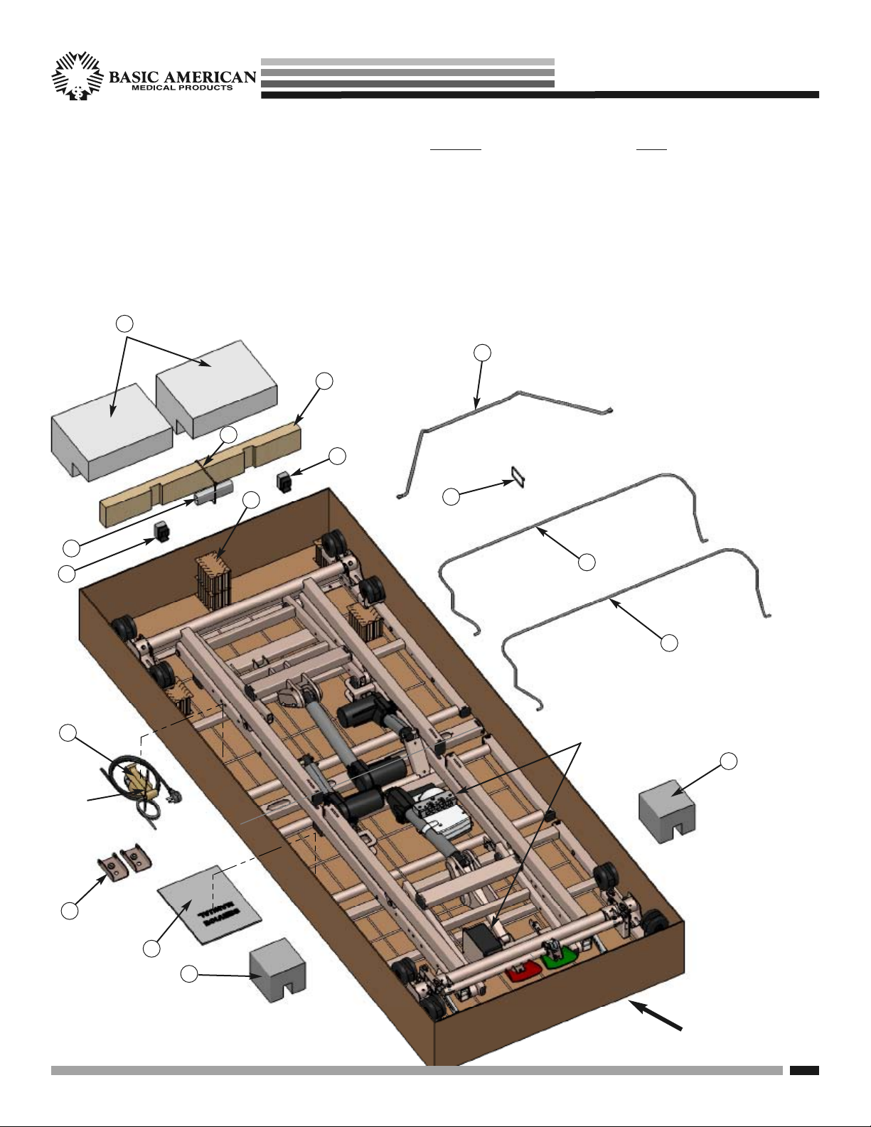
Zenith aps seRies
UNPACKING YOUR BED
•
Make sure all parts/components are included.
•
Check all bed components for obvious damage.
•
Inspect the Power Supply Cord for any cuts
and/or damage.
•
Check to see all actuator/motor cables are routed
and connected properly to the control box.
DISCARD
1. Cardboard Blocks
2. Large Block
3. Large Cable Tie - CUT
4. Notched 2 x 4 Board
5. Foam Wrapping
6. End Caps with Foam
7. Notched Leg Foam
8. Small Cable Tie - CUT
KEEP
9. Wireform Wallsaver
10. Two Mattress Retainers
11. Service Manual/Documents
12. Wallsaver Adaptor Brackets for
Trendelenberg and Reverse
Trendelenberg Positioning
13. Pendant Holster
(attached to pendant)
NOTE: END OF POWER CABLE
IS COILED FOR SHIPPING AND
TIED, WITH CABLE TIE, TO GRID
WIRE ALONG WITH PENDANT,
PENDANT CABLE & HOLSTER.
PLEASE CUT AND DISCARD
CABLE TIE AROUND CABLES
WHEN YOU UN-PACK YOUR BED.
ALSO
DISCARD TOP
AND BOTTOM
CARTONS
1
2
5
6
6
4
7
10
10
8
9
7
12
11
13
3
Cut and
discard
cable tie.
NOTE:
Underbed Light is optional and available on
APS981741 Models.
Underbed Light and Mounted Battery optional
combination is available on APS981742 Models.
Basic American Medical Products, a division of GF Health Products, Inc. www.grahamfield.com 999-0831-190A Service Manual
10
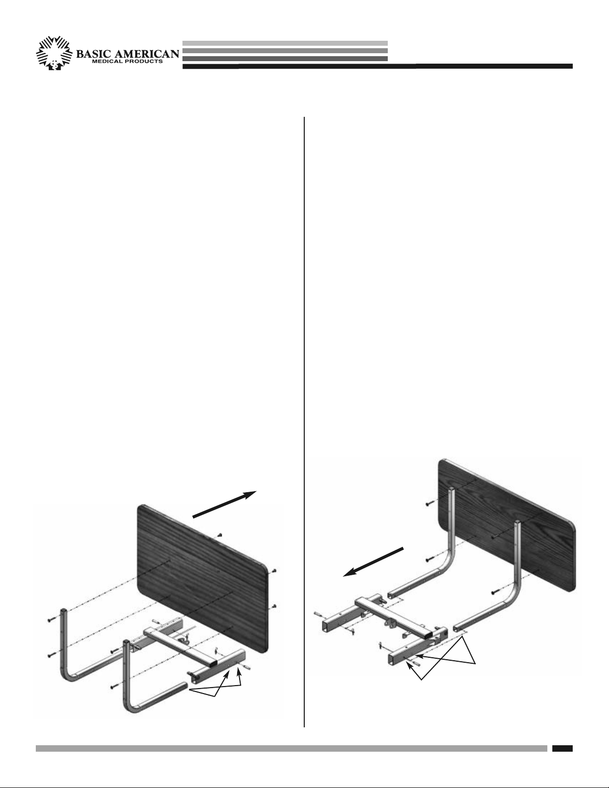
1. HEADBOARD INSTALLATION
• The headboard comes with four pre-installed
inserts - consider this the inside of the board.
• Position 2 mounting tubes on the outside of
the headboard with “L” facing inward.
• Align the top hole of the mounting tubes with
the top holes in the headboard.
• Insert a 40mm hex drive bolt through each of
the top holes and bottom holes and screw into
each insert. Tighten with the Hex Allen wrench
included in your kit.
• Slide the “L” portions of the Mounting tubes
into the hollow ends of the main frame rails,
at the head deck end.
• FOR 80” BEDS: Slide the mounting tubes in
until the 1ST hole in the tubes lines up with
the 1ST hole in the rails. See sample below.
• FOR 76” BEDS: Slide the mounting tubes in
until the 1ST hole in the tubes lines up with
the 2ND hole in the rails. See sample below.
2. FOOTBOARD INSTALLATION
• The footboard comes with four pre-installed
inserts - consider this the outside of the board.
• Position 2 mounting tubes on the inside of the
footboard with “L” facing outward.
• Align the top hole of the mounting tubes with
the top holes in the footboard.
• Insert a 40mm hex drive bolt through each of
the top holes and bottom holes and screw into
each insert. Tighten with the Hex Allen wrench
included in your kit.
• Slide the “L” portions of the Mounting tubes
into the hollow ends of the main frame rails,
at the foot deck end.
• FOR 80” BEDS: Slide the mounting tubes in
until the 1ST hole in the tubes lines up with
the 2ND hole in the rails. See sample below.
• FOR 76” BEDS: Slide the mounting tubes in
until the 1ST hole in the tubes lines up with
the 3RD hole in the rails. See sample below.
HEADBOARD FOOTBOARD
Inserts
on inside
40mm
Bolts
1st
hole
1st
hole
CENTER
OF BED
CENTER
OF BED
80” hole
position
(1st hole in)
80” hole position
(2nd hole in)
76” hole
position
(2nd hole in)
76” hole position (3rd hole in)
Inserts
on outside
40mm
Bolts
NOTE: The first hole at the foot end is reserved
for attaching the Optional 4” pan extension.
Zenith aps seRies
HEAD- AND FOOTBOARD ASSEMBLY
$OLJQ
$UURZV
3KLOOLSV6FUHZV
DWWDFK6KURXG
6WDII&RQWURO
$VVHPEO\IURP
LQVLGHRIERDUG
6WDII&RQWURO
$VVHPEO\
6KURXG
&DEOH&RYHU
)RRW%RDUG
ZLWKFXWRXW
&DEOH7LH
6WDII&RQWURO
$VVHPEO\
FDEOHWR
PRXQWLQJWXEH
)227
(1'
/RRS0DOH6WDII&RQURO&DEOH
DQGFDEOHWLHWKURXJKPRXQWLQJ
WXEHKROHZLWK)HPDOH6WDII
&RQWURO&DEOH
)HPDOHHQGRI6WDII&RQWURO
$VVHPEO\&DEOHSOXJVLQWR7&DEOH
(QGRI'RXEOH7&DEOHDWIRRWHQG*UH\
7UXQVRQHLWKHUVLGHRI6HDW3DQ
IRUDWWDFKLQJ\RXU+DQG&RQWUROOHU
/RFNLQJ(QG&DSRQ'RXEOH7&DEOH
Basic American Medical Products, a division of GF Health Products, Inc. www.grahamfield.com 999-0831-190A Service Manual
11
Zenith aps seRies
PLUGGING IN THE FOOTBOARD NURSE/STAFF CONTROL
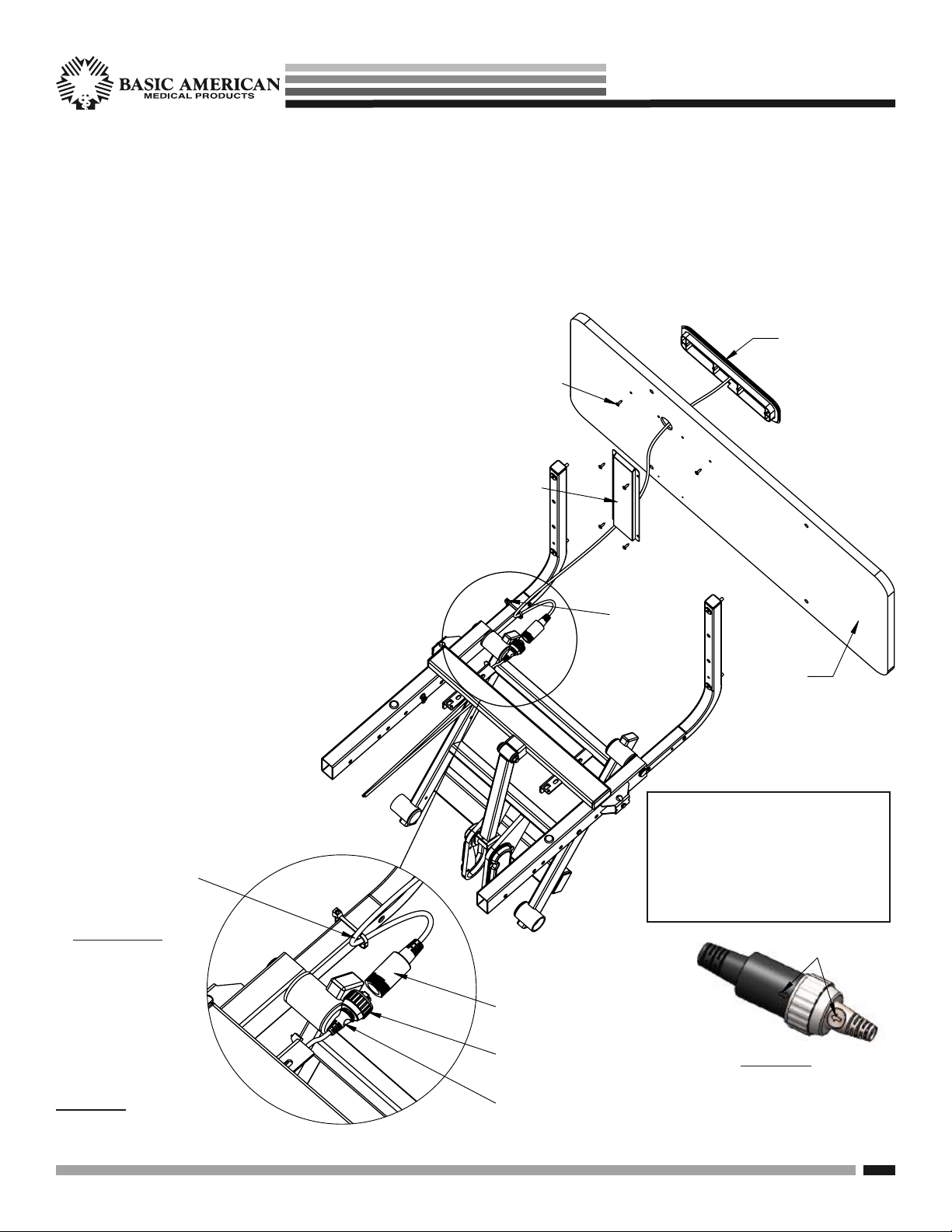
STEP 1 - ATTACHING THE FOOTBOARD
The APS 9000 bed features a Nurse/Staff Controller in the footboard, however the board is ordered separately with your
bed because of the variety of board styles available. If ordered at the same time as the bed, the Staff Control Assembly
and Shroud Cover will be pre-installed to the Footboard at the manufacturing factory.
STEP 2 - CONNECTING YOUR CABLES
Please refer to DETAIL A shown below.
a. If the Staff Control Assembly is not installed at the
factory you will need to first attach it to the footboard.
b. With the cutout side of the footboard facing outward
as shown, insert the staff control cable through the
large round hole.
c. With text right-side-up, insert the staff control
assembly into the cutout slot on the footboard
and attach to the board using the two outside
small holes and two screws from your staff
control hardware kit.
d. Attach the Shroud Cover over the cable on the
inside of the board using the four remaining
screws from your kit.
e. Insert the T-Cable end (extending out the
foot end with phone jack) into the round
plug, making sure the phone jack is
seated correctly inside the female plug
(arrow to arrow - see DETAIL B.)
f. Screw on the round lock cap onto
the Staff control’s female plug to
secure (see DETAIL B).
g. IMPORTANT
:
Make sure to tie
off the staff control
cable to the foot-
board mounting
tube with a cable
tie as shown.
DETAIL A
:
CLOSEUP OF STAFF
CONTROL CABLE CONNECTION
DETAIL B
:
MAKE SURE LOCK
END CAPS ARE
SCREWED ON
SECURELY
SEE PAGE 10 OF THIS
MANUAL FOR PROPER
ASSEMBLY OF ELBOW
MOUNTING BRACKETS
(TUBES) & FOOTBOARD
Loop Male Staff Control Cable
and cable tie through mounting
tube hole with Female Staff
Control Cable.
Basic American Medical Products, a division of GF Health Products, Inc. www.grahamfield.com 999-0831-190A Service Manual
12
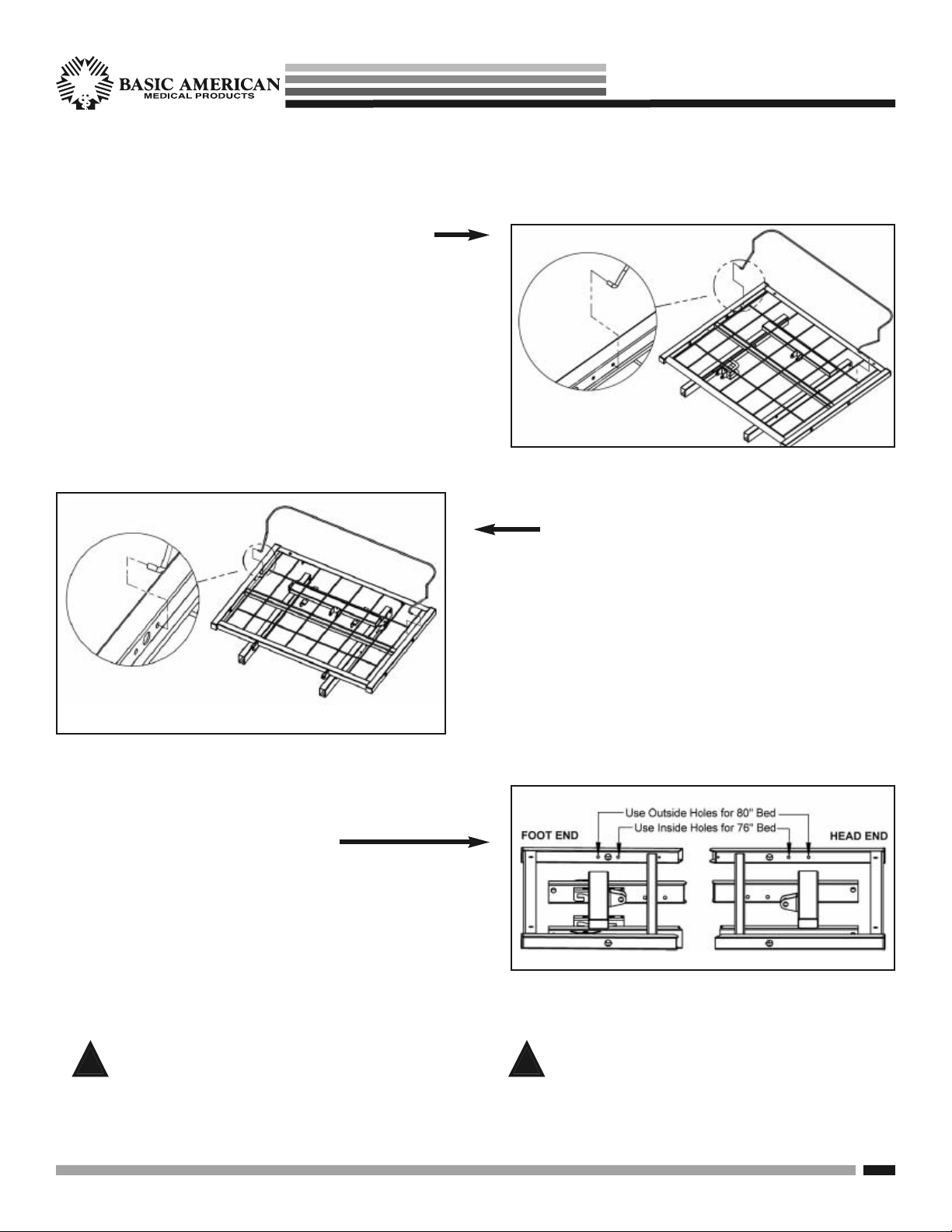
STEP 1. HEAD RETAINER INSTALLATION
1. Position retainer with curved end toward headboard.
2. Squeeze ends of the retainer toward the inside of
the bed and lower between the deck rails and first
outside grid wires.
3. Align the ends of retainer with small holes on the
inside of deck rails and slowly release.
STEP 2. FOOT-END RETAINER
INSTALLATION
1. Position retainer with curved end toward footboard.
2. Squeeze ends of the retainer toward the inside of
the bed and lower between the deck rails and first
outside grid wires.
3. Align the ends of retainer with small holes on the
inside of deck rails and slowly release.
STEP 3. RETAINER POSITIONS
• FOR 80” BEDS: Use outside small holes.
See sample at right.
• FOR 76” BEDS: Use inside small holes.
See sample at right.
!
Be sure to use a mattress that is properly sized to fit
the sleep deck, which will remain centered on the
deck relative to State and Federal Guidelines. Use
of an improperly fitted mattress could result in injury
or death.
!
Use a properly sized mattress in order to minimize
the gap between the side of the mattress and assist
devices. This gap must be small enough to prevent
resident/patient from getting his/her head or neck
caught in this location.
Zenith aps seRies
STANDARD MATTRESS RETAINER INSTALLATION
 Loading...