


REPAIR
Important Safety Instructions
Read all warnings and instructions in this manual. Save these instructions.
309063F
First choice when quality counts.t
- For portable spray applications of architectural paints and coatings -
190ESt
Airless Paint Sprayers
3000 psi (207 bar, 20.7 MPa ) Maximum Working Pressure
120 VAC
232900, A, B, C, D, E, F 232901, A, B, C, D, E 233797, A, B, C, D, E 233815, A, B, C, D, E
100-120 VAC
232903, A, B
220-240 VAC |
ti7400a |
232906, A, B
232900
. . . . . . . 309365 |
309060 |
|
|
. . . . . . . 309045 |
|
. . . . . . . . . . . . . . . . . . . . . |
309064 |
. . . . . . . 309065 |
|
Table of Contents
Component Function and Identification . . . . . . . . . . . |
. 5 |
Pressure Control Repair . . . . . . . . . . . . . . . . . . . . . . . |
19 |
|
Pressure Relief Procedure . . . . . . . . . . . . . . . . . . . . . . |
. 6 |
Drive Housing Replacement . . . . . . . . . . . . . . . . . . . . |
24 |
|
General Repair Information . . . . . . . . . . . . . . . . . . . . . . |
7 |
Motor Replacement |
25 |
|
Grounding |
8 |
|||
Displacement Pump Replacement |
26 |
|||
Troubleshooting |
9 |
|||
Technical Data |
27 |
|||
Spin Test |
12 |
|||
Graco Phone Number |
28 |
|||
Motor Brush Replacement . . . . . . . . . . . . . . . . . . . . . |
12 |
|||
On/Off Switch Replacement . . . . . . . . . . . . . . . . . . . . |
14 |
Graco Warranty . . . . . . . . . . . . . . . . . . . . . . . . . . . . . . . |
28 |

Specifications
This equipment is not intended for use with flammable or combustible materials used in places such as cabinet shops or other “factory” or fixed locations. If you intend to use this equipment in this type of application, you must comply with NFPA 33 and OSHA requirements for the use of flammable and combustible materials.
Warnings
Warning Symbol
 WARNING
This symbol alerts you to the possibility of serious injury or death if you do not follow the instructions.
Caution Symbol
CAUTION
This symbol alerts you to the possibility of damage to or destruction of equipment if you do not follow the instructions.
2 309063

The following are general Warnings related to the safe setup, use, maintenance and repair of this equipment. Additional, more specific warnings may be found throughout the text of this manual where applicable.
 WARNING
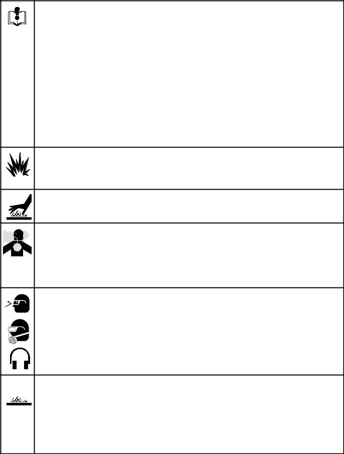
FIRE AND EXPLOSION HAZARD
Flammable fumes, such as solvent and paint fumes, in work area can ignite or explode. To help prevent fire and explosion:
D Use equipment only in well ventilated area.
D When flammable liquid is used in or near sprayer or for flushing or cleaning, keep sprayer at least 20 feet (6 m) away from explosive vapors.
D Eliminate all ignition sources; such as pilot lights, cigarettes, portable electric lamps, and plastic drop clothes (potential static arc).
D Keep work area free of debris, including solvent, rags and gasoline.
D Do not plug or unplug power cords, or turn lights on or off when flammable fumes are present. D Ground equipment and conductive objects in work area. See Grounding instructions.
D Use only grounded hoses.
D Hold gun firmly to side of grounded pail when triggering into pail.
DIf there is static sparking or you feel a shock, stop operating immediately. Do not use equipment until you identify and correct the problem.
D Keep a fire extinguisher in the work area.
ELECTRIC SHOCK HAZARD
Improper grounding, setup, or usage of the system can cause electric shock.
D Turn off and disconnect power cord before servicing equipment.
D Use only grounded electrical outlets
D Use only 3--wire extension cords.
D Ensure ground prongs are intact on sprayer and extension cords.
SKIN INJECTION HAZARD
High pressure fluid from gun, hose leaks, or ruptured components will pierce skin. This may look like just a cut, but it is a serious injury that can result in amputation. Get immediate surgical treatment.
D Do not point gun at anyone or any part of the body. D Do not put your hand over the spray tip.
D Do not stop or deflect leaks with your hand, body, glove, or rag. D Do not spray without tip guard and trigger guard installed.
D Engage trigger lock when not spraying.
DFollow Pressure Relief Procedure in this manual, when you stop spraying and before cleaning, checking or servicing equipment.
309063 3
EQUIPMENT MISUSE HAZARD
Misuse can cause death or serious injury.
INSTRUCTIONS D Do not exceed the maximum working pressure or temperature rating of the lowest rated system component. Read Technical Data in all equipment manuals.
DUse fluids and solvents that are compatible with equipment wetted parts. Read Technical Data in all equipment manuals. Read fluid and solvent manufacturer’s warnings.
D Check equipment daily. Repair or replace worn or damaged parts immediately. D Do not alter or modify equipment.
D Use equipment only for its intended purpose. Call your Graco distributor for information.
D Route hoses and cables away from traffic areas, sharp edges, moving parts and hot surfaces. D Do kink or overbend hoses or use hoses to pull equipment.
D Keep children and animals away from work area. D Comply with all applicable safety regulations.
PRESSURIZED ALUMINUM PARTS HAZARD
Do not use 1,1,1-trichloroethane, methylene chloride, other halogenated hydrocarbon solvents or fluids containing such solvents in pressurized aluminum equipment. Such use can cause serious chemical reaction and equipment rupture, and result in death, serious injury, and property damage.
BURN HAZARD
Equipment surfaces can become very hot during operation. To avoid sever burns, do not touch hot equipment. Wait until equipment has cooled completely.
TOXIC FLUID HAZARD
Toxic fluid or fumes can cause serious injury or death if splashed in the eyes or on skin, inhaled, or swallowed.
D Read MSDS’s to know the specific hazards of the fluids you are using.
DStore hazardous fluid in approved containers and dispose of it according to all applicable guidelines.
PERSONAL PROTECTIVE EQUIPMENT
You must wear appropriate protective equipment when operating, servicing, or when in the operating area of the equipment to help protect you from serious injury, including eye injury, inhalation of toxic fumes, burns, and hearing loss. This equipment includes, but is not limited to:
D Protective eye wear.
D Clothing and respirator as recommended by the fluid and solvent manufacturer. D Gloves.
D Hearing protection.
 MOVING PARTS HAZARD
Moving parts can pinch or amputate fingers and other body parts.
D Keep clear of moving parts.
D Do not operate equipment with protective guards or covers removed.
DPressurized equipment can start without warning. Before checking, moving, or servicing equipment, follow the Pressure Relief Procedure in this manual. Disconnect power or air supply.
4 309063

Component Identification and Function
|
H |
|
A |
|
J |
V |
B |
|
|
|
U |
R |
P S |
T |
|
|
K |
|
|
F |
|
|
D |
|
|
ti7400a |
|
|
ti5914a |
N |
|
E G |
|
M |
|
A |
Motor |
DC motor, permanent magnet, fan cooled |
B |
Drive Assembly |
Transfers power from DC motor to displacement pump |
D |
Displacement Pump |
Transfers fluid to be sprayed from source through spray gun |
E |
Fluid Outlet |
Spray gun is connected here |
F |
Prime Valve |
Used to prime and drain sprayer (also relieves fluid outlet pressure) when |
|
|
open |
G |
Fluid Filter (optional) |
Final filter of fluid to spray gun |
H |
Pressure Adjusting Knob |
Controls fluid outlet pressure |
J |
Pressure Control |
Controls motor speed to maintain fluid outlet pressure at displacement pump |
|
|
outlet. Works with pressure adjusting knob. |
K |
ON/OFF Switch |
Power switch that controls main power to sprayer |
M |
50 ft (15 m) Main Hose |
1/4 in. ID, grounded, nylon hose with spring guards on both ends |
N |
Spray Gun |
High pressure spray gun with gun safety latch |
P |
RAC IV Switch Tip |
Uses high pressure fluid to clear tip clogs without removing tip from spray gun |
R |
Tip Guard |
Tip guard reduces risk of injection injury |
S |
Thumb Lock Safety |
Gun safety latch inhibits accidental triggering of spray gun |
T |
Power Cord Rack |
Holds wrapped power cord for storage |
U |
Suction Hose |
Transfers fluid to be sprayed from source to pump |
V |
Drain Tube |
Fluid outlet used to drain and prime the sprayer |
309063 5
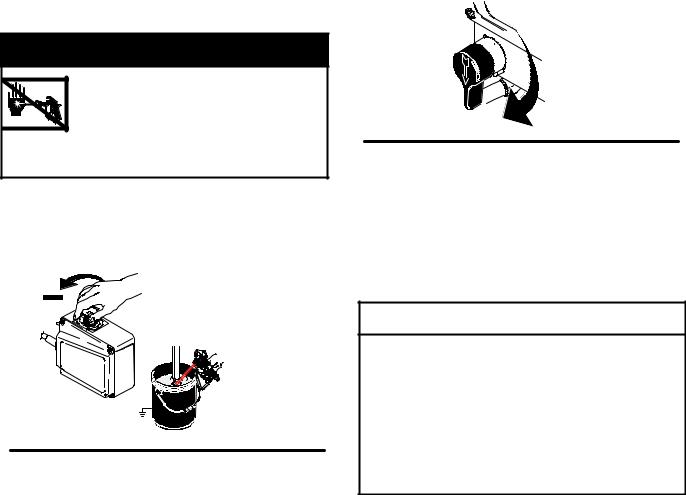
Pressure Relief Procedure
 WARNING
SKIN INJECTION HAZARD
Follow this Pressure Relief Procedure whenever you are instructed to relieve pressure, stop spraying, check or service equipment, or install or clean spray tip. read
Injection Hazard Warning.
1.Turn OFF power and turn pressure control to lowest pressure setting.
2.Hold gun against side of grounded metal flushing pail. Trigger gun to relieve pressure.
|
ti7401a |
Fig. 1 |
FLUSH |
3. Turn prime valve down
Fig. 2
If suspected that spray tip or hose is clogged or that pressure has not been fully relieved after following steps above , VERY SLOWLY loosen tip guard retaining nut or hose end coupling to relieve pressure gradually, then loosen completely. Clear tip or hose obstruction.
4.Engage trigger safety lock on gun if unit is being shut down or left unattended.
 CAUTION
To reduce risk of pressure control malfunction:
DUse needle nose pliers to disconnect wire. Never pull on wire, pull on connector.
DMate wire connectors properly. Center flat blade of insulated male connector in female connector.
DRoute wires carefully to avoid interference with other connections of pressure control. Do not pinch wires between cover and control box.
6 309063
General Repair Information
 WARNING
Read Electric Shock Warning and
Burn Hazard Warning.
 WARNING
Flammable materials spilled on hot, bare, motor could cause fire or explosion. To reduce risk of burns, fire or explosion, do not operate sprayer with cover removed.
DKeep all screws, nuts, washers, gaskets, and electrical fittings removed during repair procedures. These parts usually are not provided with replacement kits.
D test repairs after problems are corrected.
DIf sprayer does not operate properly, review repair procedure to verify you did it correctly. See Troubleshooting, page 9.
DOverspray may build up in the air passages. Remove any overspray and residue from air passages and openings in the enclosures whenever you service sprayer.
DDo not operate the sprayer without the motor shroud in place. replace if damaged. Motor shroud directs cooling air around motor to prevent overheating and insulate the control board from accidental electric shock.
 WARNING
To reduce risk of serious injury, including electric shock:
DDo not touch moving or electric parts with fingers or tools while testing repair
DUnplug sprayer when power is not required for testing
DInstall all covers, gaskets, screws and washers before you operate sprayer
 CAUTION
DDo not run sprayer dry for more than 30 seconds. Doing so could damage pump packings.
DProtect the internal drive parts of this sprayer from water. openings in the cover allow for air cooling of the mechanical parts and electronics inside. If water gets in these openings, sprayer could malfunction or be permanently damaged.
DPrevent pump corrosion and damage from freezing. Never leave water or water--base paint in sprayer when it is not in use in cold weather. Freezing fluids can seriously damage sprayer. Store sprayer with Pump armour to protect sprayer during storage.
DDo not operate the sprayer without the motor shroud or control box cover in place. Replace if damaged. Motor shroud directs cooling air around motor to prevent overheating and the control box cover insulates the control board from accidental electric shock.
309063 7
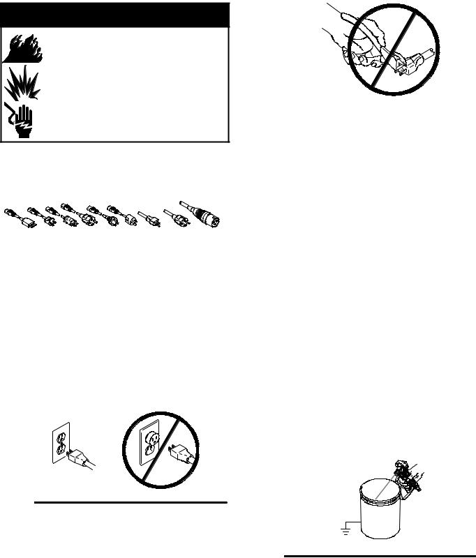
Grounding and Electric Requirements
 WARNING
Your system must be grounded. Read warnings, page 3.
The sprayer cord includes: a grounding wire with an appropriate grounding contact.
|
ti7480a |
|
Fig. 3 |
||
|
The sprayer requires:
110--120V units: 100--130 VAC, 50/60 Hz, 15A, 1 phase, circuit with a grounding receptacle.
240V Units: 210--255 VAC, 50/60 Hz, 7.5A, 1 phase, circuit with a grounding receptacle.
Never use an outlet that is not grounded or an adapter.
|
ti7482a |
|
Fig. 5 |
||
|
Recommended extension cords for use with this sprayer:
D110--120V: 3--wire, 12 AWG (2.5 mm2) minimum, 300 ft. (90 m) maximum length.
D240V: 3--wire, 16 AWG (1.0 mm2) minimum, 300 ft. (90 m) maximum length.
Smaller gauge or longer extension cords may reduce sprayer performance.
Spray gun: ground through connection to a properly grounded fluid hose and pump.
Fluid supply container: follow local code.
Solvent and Oil--based fluids: follow local code. Use only conductive metal pails placed on a grounded surface such as concrete. Do not place the pail on a nonconductive surface such as paper or cardboard, which interrupts grounding continuity.
Grounding the metal pail: connect a ground wire to the pail by clamping one end to pail and other end to ground such as a water pipe.
To maintain grounding continuity when flushing or relieving pressure: hold metal part of the spray gun firmly to the side of a grounded metal pail, then trigger the gun.
ti7481a |
|
|
|
Fig. 4 |
|
|
|
Do not use the sprayer if the electrical cord has a |
|
|
|
damaged ground contact. Only use an extension cord |
Fig. 6 |
ti7483a |
|
with an undamaged ground contact. |
|||
|
8 309063
Troubleshooting
Relieve pressure; page 6.
MOTOR WON’T OPERATE
TYPE OF PROBLEM |
WHAT TO CHECK |
WHAT TO DO |
|||
|
If check is OK, go to next check |
When check is not OK refer to this column |
|||
|
|
|
|
|
|
Basic Fluid Pressure |
1. |
Pressure control knob setting. Motor will not run |
1. |
Slowly increase pressure setting to see if mo- |
|
Problems |
|
if at minimum setting (fully counterclockwise). |
|
tor starts. |
|
|
|
|
|
|
|
|
2. |
Spray tip or fluid filter may be clogged. |
2. |
Relieve pressure and clear clog or clean fil- |
|
|
|
|
|
ter; refer to separate gun or tip instruction |
|
|
|
|
|
manual. |
|
|
|
|
|
|
|
Basic Mechanical |
1. |
Pump (13) frozen or hardened paint. |
1. |
Thaw sprayer if water or water-based paint |
|
Problems |
|
|
|
has frozen in sprayer. Place sprayer in warm |
|
|
|
|
|
area to thaw. Do not start sprayer until |
|
|
|
|
|
thawed completely. If paint hardened (dried) |
|
|
|
|
|
in sprayer, replace pump packings. See |
|
|
|
|
|
page 26 (Displacement Pump Replace- |
|
|
|
|
|
ment). |
|
|
|
|
|
|
|
|
2. |
Displacement pump connecting rod pin (9a). |
2. |
Push pin into place and secure with spring re- |
|
|
|
Pin must be completely pushed into connecting |
|
tainer. |
|
|
|
rod (9) and retaining spring (9b) must be firmly |
|
|
|
|
|
in groove of pump pin. See Fig. 18. |
|
|
|
|
|
|
|
|
|
|
3. |
Motor (1). Remove drive housing assembly |
3. |
Replace motor (1) if fan won’t turn. See page |
|
|
|
(10). See page 24. Try to rotate fan by hand. |
|
25. |
|
|
|
|
|
|
|
Basic Electrical Problems |
1. |
Motor control board. Board shuts down and dis- |
1. |
See Motor Control Board Diagnostics, |
|
See Wiring Diagram, pages |
|
plays error code on some models. |
|
page 19. |
|
15 to 18. |
|
|
|
|
|
2. |
Electrical supply. Meter must read 100--130 |
2. |
Reset building circuit breaker; replace build- |
||
|
|||||
|
|
VAC for 110--120 VAC models and 210--255 |
|
ing fuses. Try another outlet. |
|
|
|
VAC for 240 VAC models. |
|
|
|
|
|
|
|
|
|
|
3. |
Extension cord. Check extension cord continu- |
3. |
Replace extension cord. |
|
|
|
ity with volt meter. |
|
|
|
|
|
|
|
|
|
|
4. |
Sprayer power supply cord. Inspect for damage |
4. |
Replace power supply cord. |
|
|
|
such as broken insulation or wires. |
|
|
|
|
|
|
|
|
|
|
5. |
Fuse. Check replaceable fuse on control board. |
5. |
Replace fuse after completing motor inspec- |
|
|
|
|
|
tion. |
|
|
|
|
|
|
|
|
6. |
Motor leads are securely fastened and properly |
6. |
Replace loose terminals; crimp to leads. Be |
|
|
|
connected to control board. |
|
sure terminals are firmly connected. |
|
|
|
|
|
Clean circuit board terminals. Securely re- |
|
|
|
|
|
connect leads. |
|
|
|
|
|
|
|
|
7. |
Motor thermal switch. Yellow motor leads must |
7. |
Replace motor. See page 25, Motor Re- |
|
|
|
have continuity through thermal switch. |
|
placement. |
|
|
|
|
|
|
|
|
8. |
Brush cap missing or loose brush lead connec- |
8. |
Install brush cap or replace brushes if leads |
|
|
|
tions. |
|
are damaged. See page 12, Motor Brush Re- |
|
|
|
|
|
placement. |
|
|
|
|
|
|
|
|
9. |
Brush length which must be 1/4 in. (6 mm) mini- |
9. |
Replace brushes. See page 12, Motor Brush |
|
|
|
mum. |
|
Replacement. |
|
|
|
NOTE: Brushes do not wear at the same rate on |
|
|
|
|
|
both sides of motor. Check both brushes. |
|
|
|
|
|
|
|||
|
10.Motor armature commutator for burn spots, |
10. Remove motor and have motor shop resur- |
|||
|
|
gouges and extreme roughness. |
|
face commutator if possible. See page 25, |
|
|
|
|
|
Motor Replacement. |
|
|
|
|
|||
|
11. Motor armature for shorts using armature tester |
11. Replace motor. See page 25, Motor Re- |
|||
|
|
(growler) or perform spin test, page 12. |
|
placement. |
|
12.Pressure control not plugged in to control board. 12.Insert pressure control connector into control board.
309063 9
 Loading...