


Graco Inc Hydra-Clean 824-001, Hydra-Clean 824-007, Hydra-Clean 2800, Hydra-Clean 824-006 User Manual
|
|
|
|
|
|
|
|
|
OWNER'S |
|
|
|
|
|
|
|
|
|
MANUAL |
|
|
|
|
|
|
|
|
|
824±001 |
|
|
|
|
|
|
|
|
This manual contains important |
|
|
|
|
|
|
|
|
|
warnings and information. |
Rev D |
|
|
|
|
|
|
|
|
READ AND RETAIN FOR REFERENCE |
|
|
|
|
|
|
|
|
|
|
Supercedes Rev. C |
|
|
|
|
|
|
|
|
|
HYDRA-CLEAN 2000, 2800
Pressure Washers
Hydra-clean 2000
824±006 Series A
2000 psi (138 bar) Operating Pressure
2400 psi (165 bar) Maximum Working Pressure
Hydra-clean 2800
824±007, Series A
2800 psi (193 bar) Operating Pressure
3200 psi (225 bar) Maximum Working Pressure


Model 824±006
The SHERWIN±WILLIAMS COMPANY, 101 PROSPECT AVENUE, CLEVELAND, OHIO 44115
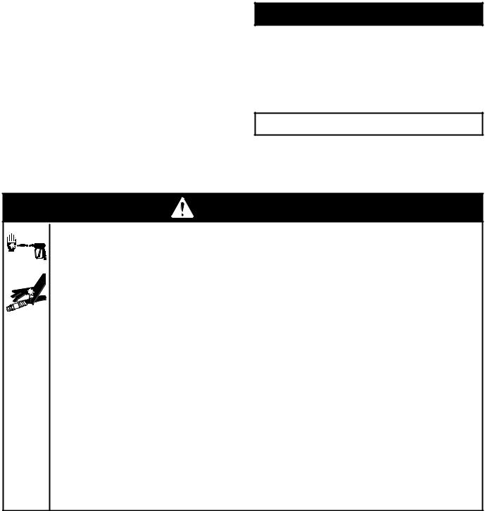
Table of Contents
Warnings . . . . . . . . . . . . . . . . . . . . . . . . . . . . . . . . . . . . . . 2
Installation . . . . . . . . . . . . . . . . . . . . . . . . . . . . . . . . . . . . . . . . . . . . . . 4
Operation . . . . . . . . . . . . . . . . . . . . . . . . . . . . . . . . . . . . . . . . . . . . . . . 5
Troubleshooting . . . . . . . . . . . . . . . . . . . . . . . . . . . . . . . . . . . . . . . . 9
804±544 Pump Service . . . . . . . . . . . . . . . . . . . . . . . . 11
804±559 Pump Service . . . . . . . . . . . . . . . . . . . . . . . . 13
Accessories . . . . . . . . . . . . . . . . . . . . . . . . . . . . . . . . . . 15
Technical Data . . . . . . . . . . . . . . . . . . . . . . . . . . . . . . . . 15
Parts List & Drawing
Hydra-clean 2000 Pressure Washer . . . . . . . . . . . . 16
Hydra-clean 2800G Pressure Washer . . . . . . . . . . . 18
Pump Assembly Model 804±544 . . . . . . . . . . . . . . . . 20
Pump Assembly Model 804±559 . . . . . . . . . . . . . . . . 22
Warranty . . . . . . . . . . . . . . . . . . . . . . . . . . . . . . . . . . . . . 24
Warning Symbol
 WARNING
This symbol alerts you to the possibility of serious injury or death if you do not follow the instructions.
Caution Symbol
 CAUTION
This symbol alerts you to the possibility of damage to or destruction of equipment if you do not follow the instructions.
WARNING
INJECTION HAZARD
Spray from the gun, leaks or ruptured components can inject fluid into your body and cause serious injury. Fluid splashed in the eyes or on the skin can also cause serious injury.
DFluid injected into the skin may look like just a cut, but it is a serious injury. Get emergency medical attention.
DDo not point gun at anyone or at any part of body.
DDo not stop or deflect leaks with hand, body, glove or rag.
D Do not put hand or fingers over spray tip.
DTighten fluid connections before starting equipment.
DEngage the gun trigger safety whenever you stop spraying.
DFollow Pressure Relief Procedure on page 5 if spray tip clogs and before cleaning, checking or servicing equipment.
DRepair or replace worn or damaged parts immediately.
DCheck hoses, tubes, and coupling daily. Do not repair high pressure couplings: replace entire hose. Fluid hoses must have spring guards on both ends to prevent kinks and rupture.
824±001
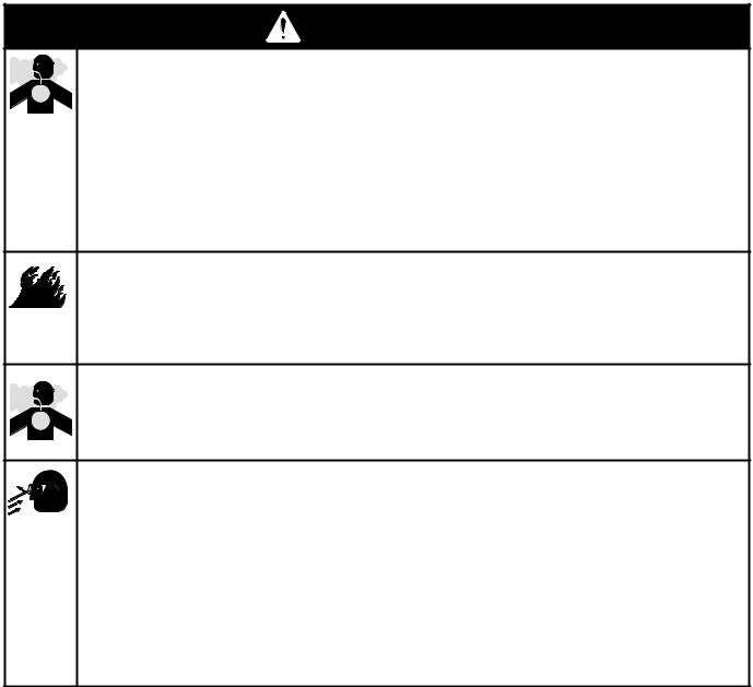
WARNINGG
HAZARDOUS FLUIDS
Improper handling of hazardous fluids can cause serious injury, even death, due to splashing in eyes, ingestion or bodily contamination.
DKnow specific hazards of fluid being used.
DStore hazardous fluids in approved containers. Dispose of hazardous fluids per local, state and national guidelines.
DWear protective eyewear, gloves, clothing, and respirator as recommended by the fluid manufacturer.
FUEL HAZARD
The fuel used in this unit is combustible and when spilled on a hot surface can ignite and cause a fire.
D Do not fill the fuel tank while the engine is running or hot.
EXHAUST HAZARD
The exhaust contains poisonous carbon dioxide which is colorless and odorless.
D Do not operate this equipment in a closed building.
EQUIPMENT MISUSE HAZARD
Misuse of the pressure washer or accessories may cause them to rupture and result in fluid injection, splashing in the eyes or on the skin, or other serious injury.
DDo not alter or modify any part or factory-set adjustment of this equipment.
DDo not exceed the maximum working pressure of any component or accessory in the system.
DDo not use any chemicals that are incompatible with the wetted parts as stated in the Technical Data.
DDo not alter throttle setting.
824±001 3

Installation
Typical Installation ± Pressure Washer
HOSE
RACK
SPRAY
GUN
SPRAY
HOSE
Fig. 1
INLET WATER |
HIGH PRESSURE |
CONNECTION |
HOSE CONNECTION |
3/4º GARDEN |
|
HOSE |
|
|
Check for Shipping Damage
Check the unit for any damage that may have occurred in shipping. Notify the carrier immediately if there is any damage.
Set Up
Connect the high pressure hose between the pump outlet and the gun inlet. Both of these connections are made with quick couplers.
 CAUTION
Up to 100 ft (30 m) of high pressure hose may be used. Longer hoses may affect sprayer performance, and chemical injector performance, if used.
Install the appropriate spray tip on the wand. See Installing and Changing Spray Tips. If you are using a sandblaster kit, see its separate manual for installation instructions.
Connect to Water Supply
 CAUTION
Before attaching to the water supply, check your local plumbing code regarding cross±connection to the water supply. If required, a backflow preventer may be installed.
If inlet water pressure is over 60 psi (4.1 bar), a regulating water valve must be installed at the garden hose connection.
Do not exceed 160_F (70_C) inlet water temperature.
Connect a hose with at least a 3/4 inch (19 mm) ID from the water supply to the unit's 3/4 inch garden hose inlet. The supply hose should not be more than 50 ft (15 m) long
NOTE: The water source at the unit must have a minimum flow rate equal to that of the unit (see Technical Data, inside back cover).
4824±001
Operation
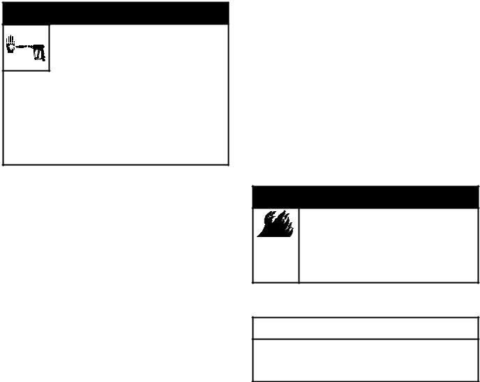
Pressure Relief Procedure
 WARNING
INJECTION HAZARD
The system pressure must be manually
relieved to prevent the system from spraying accidentally. To reduce the risk
of an injury from accidental spray from the gun, splashing fluid, or moving parts, follow the Pressure Relief Procedure whenever you:
Dare instructed to relieve the pressure,
Dstop spraying for more than 10 minutes,
Dcheck or service any of the system equipment,
Dor install or clean the spray nozzle.
Startup
Always use this start±up procedure to ensure that the unit is started safely and properly.
1. Check oil levels:
NOTE: All units are equipped with a low-oil sensor that shuts the engine off if the oil level falls below a certain level. If the unit stops unexpectedly, check both the oil and the fuel levels. Check the oil level each time the unit is refueled.
2. Check fuel level.
Pressure Relief Procedure
1.Engage the trigger safety latch.
2.Turn the sprayer off.
3.Remove the ignition cable from the spark plug.
4.Shut off the water supply.
5.Disengage the trigger safety latch and trigger the gun to relieve pressure, and then engage the trigger safety latch again.
6.If you suspect that the spray tip or hose is completely clogged, or that pressure has not been fully relieved after following the steps above:
Disengage the trigger safety latch and trigger the gun to relieve pressure. Wrap a rag around the hose end coupling and VERY SLOWLY loosen the coupling to relieve pressure gradually, then loosen completely. Now clear the tip or hose.
 WARNING
FIRE HAZARD
Do not refuel a hot engine. Refueling a hot engine could cause a fire. Use only fresh, clean regular or unleaded gasoline. Close the fuel shutoff valve during refueling.
 CAUTION
Never run the unit dry. Costly damage to the pump will result. Always be sure the water supply is completely turned on before operating.
3. Turn on the water supply.
824±001 5

Operation
4.Trigger the gun until water sprays from the tip indicating that the air is purged from the system.
5.Open the fuel shutoff valve. Be sure the spark plug ignition cable is pushed firmly onto the spark plug. Put the switch in the ªonº position and put the throttle in the ªrunº position.
 CAUTION
Do not allow the pressure washer to idle for more than 10 minutes. Doing so may cause the recirculating water to overheat and seriously damage the pump. Turn off the pressure washer if it will not be spraying or cleaning at least every 10 minutes. If heated inlet water is used, reduce this time further. Do not operate the pressure washer with the inlet water screen removed. This screen helps keep abrasive sediment out of the pump, which could clog the pump or damage the cylinders. Keep this screen clean. Do not pump caustic materials; such materials may corrode the pump components.
 CAUTION
Do not allow the starter rope to snap back against the engine. Return it gently to prevent damage to the recoil.
6. Start the engine.
NOTE: For easier starting, have one person start the pressure washer while another person triggers the spray gun.
If the engine is cold, completely close the engine choke. Grasp the starter rope, brace one foot on the pressure washer chassis and pull rope rapidly and firmly. Continue holding the rope as it returns. Pull and return the rope until the engine starts. In cool weather, the choke may have to be kept closed for 10 to 30 seconds before opening it to keep the engine running. Otherwise, open the choke as soon as the engine starts.
If the engine is warm, leave the choke open, or just partly close it. Start the engine as described in the preceding paragraph. When it starts, be sure to open the choke completely.
7.Always engage the gun's trigger safety latch whenever you stop spraying, even for a moment, to reduce the risk of fluid injection or splashing in the eyes or on the skin if the gun is bumped or triggered accidentally.
8.Always observe the following CAUTIONS to avoid costly damage to the pressure washer.
9.See the sandblaster kit manual for detailed cleaning information if this accessory is used.
6824±001
Operation
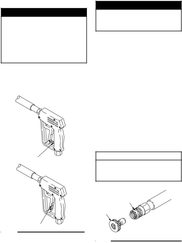
Trigger Safety Latch
 WARNING
To reduce the risk of serious bodily injury, including fluid injection, splashing in the eyes or on the skin, always engage the trigger safety latch whenever spraying stops, even for a moment.In the engaged position, the trigger safety latch prevents the gun from being triggered accidentally by hand or if it is dropped or bumped. Be sure the latch is pushed fully down when engaging it or it cannot prevent the gun from being triggered. See Figure 2.
TRIGGER SAFETY LATCH SHOWN ENGAGED
04612
TRIGGER SAFETY LATCH SHOWN DISENGAGED
Figure 2
Installing and Changing Spray Tips
 WARNING
To reduce the risk of serious bodily injury, including fluid injection or splashing in the eyes or onto the skin, use extreme caution when changing spray tips. always follow the procedure below.
1.Follow the Pressure Relief Procedure.
2.Point the gun and wand away from yourself and anyone else.
3.Spray tips have a 4± or 5±digit number on them. The first two digits are the spray angle. Select the spray tip appropriate for your application.
Spray Tip Number |
Spray Pattern Fan Angle |
|
|
00XXX |
0_, blaster (red) |
15XXX |
15_ (yellow) |
25XXX |
25_ (green) |
40XXX |
40_ (white) |
NOTE: The chemical injector tip is brass, has a large opening and a black plastic cap.
4.Without holding your hand over the spray tip (A), pull back the quick coupler ring (B). Remove the current tip and/or install a different one, and then push back the ring. See Figure 3.
5.Pull on the tip to be sure the tip is secure before starting to spray again.
6.Tip holding holes are provided on the chassis.
 CAUTION
To avoid blowing the o-ring out of the quick coupler, due to the high pressure in the system, never operate the pressure washer without a tip securely mounted in the quick coupler.
B
A
04929
Figure 3
824±001 7

Operation
Shutdown, Flushing and Storage
NOTE: An anti±freeze flush kit 802±327 is available to make flushing easier.
 CAUTION
If water does freeze in the pressure washer, thaw it in a warm room before trying to start it. Do not pour hot water on or into the pump; it may crack the ceramic plungers!
 WARNING
To reduce the risk of serious bodily injury, including fluid injection, splashing in the eyes or on the skin or injury from moving parts, always follow the
Pressure Relief Procedure on page 5 before proceeding.
1.If the pressure washer will be exposed to freezing temperatures, drain all water out of the pump. If it must be stored in freezing temperatures, flush the unit with a 50% anti±freeze solution. Relieve pressure. Flush the pressure washer before using it again to remove the anti±freeze.
2.Before long-term (overnight) storage or transporting of unit, disconnect the water supply, and turn off the fuel supply valve.
3.After each use, wipe all surfaces of the pressure washer with a clean, damp cloth.
4.Perform the appropriate maintenance. See maintenance chart.
Maintenance
Observing regular maintenance intervals helps ensure that you get maximum performance and life from the pressure washer.
There is a break-in period for the engine, pump and gear reducer (if used). After changing the oil in these components following their respective break-in periods, the interval between required changes is longer.
If the unit is operating in dusty conditions, these maintenance checks should be made more often.
Interval |
What to do |
|
|
Daily |
Clean water inlet screen and filter. |
|
Check engine and pump oil levels. |
|
Fill as necessary. Check gasoline |
|
level. Fill as necessary. |
|
|
After first 5 |
Change engine break±in oil. Drain |
hours of opera- |
oil when warm. Use SAE 30 or |
tion |
10W±30 detergent oil. |
|
|
Each 25 hours |
Clean and remove air cleaner |
of operation |
foam. Wash with water and deter- |
|
gent. Dry thoroughly. Rub with oil |
|
and squeeze to distribute oil. |
|
|
After first 50 |
Change pump break-in oil. Use |
hours of opera- |
SAE 20 or 30 non-detergent oil. |
tion |
|
|
|
Each 100 |
Clean or replace paper air cleaner |
hours of opera- |
cartridge. Tap gently to remove |
tion |
dirt. Change engine oil. Use SAE |
or 3 months |
30 or 10W±30 detergent oil. |
|
|
Each 500 |
Change pump oil. Use SAE 20 or |
hours of opera- |
30 non-detergent oil. |
tion |
|
or 6 months |
|
|
|
8824±001
 Loading...